ISSN (e): 2250-3021, ISSN (p): 2278-8719
Vol. 09, Issue 7 (July. 2019), ||S (II) || PP 61-65
Voltage Control with Electric Springs
Buchi Pavan Kumar¹P Balanagu²
¹PG Scholar, Dept. Of EEE, Chirala Engineering College, Chirala, India ²Associate Professor, Dept.of EEE, Chirala Engineering College, Chirala, India
Corresponding Author: Buchi Pavan Kumar
Abstract
—the concept of electric spring (ES) has been proposed recently as an effective means of distributed
voltage control. The idea is to regulate the voltage across the critical (C) loads while allowing the noncritical (NC) impedance-type loads (e.g., water heaters) to vary their power consumption and thus contribute to demand-side response. In this paper, a comparison is made between distributed voltage control using ES against the traditional single point control with STATic COMpensator (STATCOM). For a given range of supply voltage variation, the total reactive capacity required for each option to produce the desired voltage regulation at the point of connection is compared. A simple case study with a single ES and STATCOM is presented first to show that the ES and STATCOM require comparable reactive power to achieve similar voltage regulation. Comparison between a STATCOM and ES is done. In both cases, it turns out that a group of ESs achieves better total voltage regulation than STATCOM with less overall reactive power capacity. Dependence of the ES capability on proportion of critical and NC load is also shown.Index Terms
—Demand response, electric springs (ES), STATic Compensator (STATCOM), voltage control,
voltage regulation.--- --- Date of Submission: 18-07-2019 Date of acceptance: 03-08-2019
---I.
INTRODUCTION
Voltage control in medium voltage (MV) or low voltage (LV) distribution networks is typically exercised through transformer tap-changers and/or switched capacitors/reactors. Sometimes a STATic COMpensator (STATCOM) is used for fast and precise voltage regulation, especially for the sensitive/critical loads [1].The novel concept of electric spring (ES) has been proposed as an effective means of distributed voltage control [2]. The idea is to regulate the voltage across the critical loads while allowing the noncritical (NC) impedance-type loads (e.g., water heaters) to vary their power consumption and thus contribute to demand-side response [3], [4] as well. This would allow and facilitate large penetration of intermittent renewable energy sources without requiring huge amounts of energy storage to act as a buffer between supply and demand [5]. The basic proof of concept of ES has already been demonstrated through hardware experimentation with the developed prototypes [2], [6]. Distributed voltage regulation through collective action of a cluster of ESs, each employing droop control has also been illustrated [7].
In this paper, the focus is to compare the effectiveness of single point voltage control using STATCOM against distributed voltage control using a group of ESs. The basis for comparison is total voltage regulation [root mean square of the deviation of the actual voltages from the rated (1.0 p.u) values] achieved and the overall reactive capability required for each option in order to achieve that [8], [9]. A number of papers [2], [5]– [7] have been published recently on the ES concept and its control. However, none of those papers have focused on the collective performance of multiple of ESs considering realistic distribution networks. This paper demonstrates the effectiveness of multiple ESs working in unison through case studies on an IEEE test feeder network and also a part of a real distribution system in Hong Kong. The voltage regulation performance and total reactive power requirement of a group of ESs in case of distributed voltage control is compared against the single-point control using a STATCOM. In both cases, it turns out that a group of ESs achieves better total voltage regulation than STATCOM with less overall reactive power capacity.
International organization of Scientific Research
62 | Page
II.
ELECTRIC SPRING (ES) CONCEPT
Voltage control in LV and MV distribution networks and demand-side management (DSM) have traditionally been treated and tackled separately. Voltage control is usually achieved by control devices discussed in the previous section. DSM, on the other hand, is employed in a more distributed fashion (often at the appliance level) and is predicated on intelligence or communication facility in the appliance [10]–[12].
Fig. 1. Electric spring set-up for smart loads.
Fig. 2. Simulation set-up with an intermittent source and an equivalent power grid.
Alternatively, an integrated approach to voltage control and aggregated demand action could be achieved by separating the loads into critical (C) loads requiring constant voltage and uninterrupted supply and NC, impedance-type loads. At times of generation shortfall or network constraint, the voltage of the NC loads is reduced while regulating the voltages across the C loads. This addresses the generation shortfall or network constraint and also facilitates better voltage regulation of the C loads through manipulation of the supply impedance voltage drop.
One way to exercise this control is to use the so-called ESs which are power electronic compensators that inject a voltage with controllable magnitude VES in series with each NC load to regulate the voltage VC across the C load as shown in Fig. 1. The voltage VNC across the NC loads is thus controlled (within allowable bounds) and the active power consumed by them modulated. The series combination of the ES and the NC load thus acts as a smart load which ensures tightly regulated voltage across the C load while allowing its own power consumption to vary and thereby, participate in demand-side response. Adding the voltage VES in quadrature with the current flowing through the ES ensures exchange of reactive power only like conventional voltage compensators including STATCOM. For further details about ESs the readers can refer to [2] and [5].
III. ES VERSUS STATCOM
A. Test System
In order to compare the voltage regulation performance of a single ES against that of a STATCOM, a simple test system as shown in Fig. 2 has been considered. It comprises of a power source acting as the main power grid and a separate controllable power source to emulate an intermittent renewable
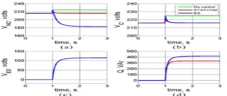
Fig. 3. System response following decrease in reactive power consumption of the intermittent source from 467 to 110 VAr. (a) Non-critical load voltage. (b)Critical load voltage. (c)Electric spring voltage. (d)Reactive power
The controllable source is capable of injecting variable active and/or reactive power which causes the voltage across the C load to fluctuate. For simplicity both C and NC loads are represented by resistors although they do not have to be necessarily resistive. The parameters used for the system and the ES are the same as in [2] and are not repeated here due to space restriction.
The above system is modeled in MATLAB/SIMULINK using a controllable voltage source representation for both ES and STATCOM. Modeling and control of ES is discussed in [13]. The magnitude of the controllable voltage representing the ES is controlled using a PI controller to minimize the difference between the actual and reference values of the voltage across the C load. Phase angle of the voltage source is locked in quadrature to the phase angle of series current to ensure there is no active power transfer. The STATCOM is modelled by a controllable voltage source in series with impedance. Its control circuit is very similar to that of ES except for the adjustments due to its parallel connection to the C and NC load.
B. Voltage Suppress Mode
The voltage across the loads is increased above the nominal value (216 V) by reducing the reactive power absorption of the renewable source. This is to test the ability of an ES and a STATCOM to suppress the voltage and regulate it at the nominal value. At t = 1.0 s, the reactive power absorption by the intermittent renewable source is reduced from 467 VAr down to 110 VAr.Without any voltage control, the load voltage increases from the nominal value of 216 V up to 224 V as shown by Fig. 3(a) and (b). Both STATCOM and ES are able to restore the voltage across the C load back to the nominal value as shown by the overlapping blue and red traces in Fig. 3(b). The ES achieves this by injecting about 115 V in series with the NC load the voltage across which drops to about 185 V as shown by the blue traces in Fig. 3(a) and (c). In order to suppress the voltage, both ES and STATCOM absorb reactive
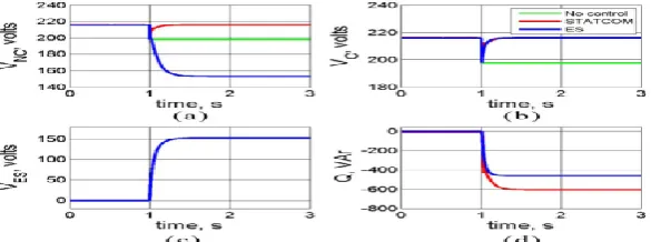
Fig. 4. System response following increase in reactive power consumption of the intermittent source from 467 to 1100 VAr. (a) Noncritical load voltage. (b)Critical load voltage. (c)Electric spring voltage. (d)Reactive power exchange.
power (as indicated by positive sign of Q) from the system as shown in Fig. 3(d) with ES requiring to absorb about 100 VAr more than the STATCOM.
It is observed that the reactive power consumed by ES to restore the C load voltage to normal value is higher than the reactive power consumed by STATCOM to achieve the same voltage. This can be explained from Fig. 1. An increase in ES voltage will result in a decrease in NC load voltage. This causes a decrease in the active power consumption of the (resistive) NC load. In order to have a higher overall active/reactive power consumption for the smart load, ES has to consume more reactive power. Note that the X/R ratio is not large (about 2) in this case which is why both active and reactive power affect the voltage regulation.
C. Voltage Support Mode
To investigate the opposite effect of what was described in the previous subsection, the voltage across the loads is reduced by increasing the reactive power absorption of the renewable source. This is to test the ability of an ES and a STATCOM to support the voltage and regulate it at the nominal value. At t = 1.0 s, the reactive power absorption by the intermittent renewable source is increased from 467 to 1100 VAr. Without any voltage control, the load voltage is seen to drop from the nominal value of 216 V to slightly below 190 V as shown by the green trace in Fig. 4(a) and (b).
International organization of Scientific Research
64 | Page
load voltage which causes a decrease in active power consumption of the (resistive) NC load. Hence, the ES needs to produce less reactive power than an equivalent STATCOM to restore the system voltage due to the similar arguments about the X/R ratio as mentioned earlier for the voltage suppress case.IV. SIMULATION RESULTS
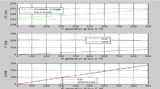
The result of varying the reactive power absorbed and the active power generated by the renewable energy source connected at bus 2 (see Fig. 2) is shown. First, the reactive power absorbed is varied between 150 and 1100VAr keeping the active power generation fixed at zero. Without any voltage control, the voltage across the loads reduces as the reactive power absorption increases. This is shown by the green trace in Fig. 7(a) about the nominal voltage of 216 V. For Q < 467 VAr, the actual voltage is higher than nominal requiring voltage suppression while for Q > 467 VAr, the actual voltage is less than the nominal requiring voltage support.
Voltage injected by the ES and the voltage across the NC load are shown in Fig. 7(b). For Q = 467 VAr, the voltage injected by the ES is almost zero while the voltage across the NC load is equal to the nominal value of 216 V. On either side of Q = 467 VAr, the ES injects a positive voltage, resulting in a reduced voltage across the NC load such that the vector sum of the two equals the nominal voltage (i.e., 216 V) which is maintained across the critical load.The reactive power exchanged by the ES is compared against that of a STATCOM to regulate the C load voltage at 216 V. It can be seen that for voltage suppression (Q < 467 VAr), both of the ES and STATCOM absorbs VAr from the system (as indicated by the positive sign) while for voltage support (Q > 467 VAr) they inject VAr into the system.
It should be noted that over the range of variation of Q absorption shown in Fig. 7(c), the reactive power exchanged by the ES and the STATCOM are very similar. For higher levels of voltage support (Q > 900 VAr), a STATCOM requires more reactive power than an ES with the difference between the two growing for larger Q absorption.
Fig. 7. Variations of the (a) voltage across the critical load, (b) voltages across the noncritical load and the ES, and (c) reactive power of the ES and STATCOM as the reactive power absorption by the renewable source (at bus 2, Fig. 2) is changed from 150 to 1100 VAr.
International organization of Scientific Research
65 | Page
V.
CONCLUSION
In this paper, a comparison is made between distributed voltage control using ES against the traditional single point control with STATCOM. For a given range of supply voltage variation, the total voltage regulation, and the total reactive capacity required for each option to produce the desired voltage regulation at the point of connection are compared. A simple case study with a single ES and STATCOM is presented first to show that the ES and STATCOM require comparable reactive power to achieve similar voltage regulation. Comparison between a STATCOM and ES is further substantiated through similar case studies on the IEEE 13-bus test feeder system and also on a part of the distribution network. In both cases, it turns out that a group of distributed ESs requires less overall reactive power capacity than STATCOM and yields better total voltage regulation. This makes ESs a promising technology for future smart grids where selective voltage regulation for sensitive loads would be necessary alongside demand-side response.
REFERENCES
[1]. N. G. Hingorani and L. Gyugyi, Understanding FACTS: Concepts and Technology of Flexible AC Transmission Systems. Piscataway, NJ, USA: IEEE Press, 2000.
[2]. S. Y. Hui, C. K. Lee, and F. F. Wu, ―Electric springs: A new smart grid technology,‖ IEEE Trans. Smart Grid, vol. 3, no. 3, pp. 1552–1561, Sep. 2012.
[3]. A. Brooks, E. Lu, D. Reicher, C. Spirakis, and B. Weihl, ―Demand dispatch,‖ IEEE Power Energy Mag., vol. 8, no. 3, pp. 20–29, May/Jun. 2010.
[4]. D. Westermann and A. John, ―Demand matching wind power generation with wide-area measurement and demand-side management,‖ IEEE Trans. Energy Convers., vol. 22, no. 1, pp. 145–149, Mar. 2007. [5]. C. K. Lee and S. Y. Hui, ―Reduction of energy storage requirements in future smart grid using electric
springs,‖ IEEE Trans. Smart Grid, vol. 4, no. 3, pp. 1–7, Sep. 2013.