Abstract— A spherical triangular finite element based on shallow shell formation is developed in this paper for linear and geometrically nonlinear analysis of spherical shells. The developed element is rectangular in-plane and has only five essential degrees of freedom at each corner node. The displacement fields of the element satisfy the exact requirement of rigid body modes. The efficiency of the element is demonstrated by applying it to the linear and geometrically nonlinear analysis of spherical shell structures. Results obtained by the present element are compared with those available in the literature. These comparisons show that efficient convergence characteristic and accurate results can be obtained by using the present element.
Index Term— Linear, non-linear, shallow shell, spherical shell.
1. INTRODUCTION
Thin-walled shell construction combine light weight with high strength, as a result of which they are finding wide application in many engineering structures such as highway bridges, aerospace and ship structures. This explains the increased interest and success achieved in this type of structures. Due to the complex shape of shell structures, analytical solutions are only available for simple cases and resort to the numerical methods such as finite analysis which is now very commonplace.
Considerable attention has been given to applying the finite element method in the analysis of curved structures. Grafton and Strome developed conical segments for the analysis of shell revolution. Later Jones and Strome modified the method and used meridional elements which were found to lead to considerably improved results for the stresses. Curved rectangular and cylindrical shell elements were also developed (Connor and Brebbia [3] Cantin and Clough [4] and Sabir and lock [5]). However, to model a shell of spherical shape using the finite element method triangular and rectangular spherical shell elements are needed.
Several spherical shell elements have been developed to analyzed shells of spherical shape. Most notably, the higher
order elements of Lindberg et al [6], Yang and Dawe [8] have resulted in an improvement of the accuracy of the results.
However this improvement is achieved at the expense of increased computational efforts and storage. Meanwhile, a simple alternative strain-based approach has been used to develop curved elements. In this approach, the exact terms representing all the rigid body modes and the displacement functions representing the element strain are determined by assuming independent strain function insofar as it is allowed by the compatibility equations (Ashwell and Sabir [9]). This approach has been employed successfully in the development of different cylindrical, hyperbolic and conical shell elements by Sabir et al [10-13] and by Mousa et al [14-17]. These elements were found to yield faster convergence when compared with other available finite elements. The strain-based approach was also used by Mousa [18] to develop rectangular spherical shell element. These spherical elements possess only the five essential external nodal degrees of freedom at each corner node and were found to have excellent convergence.
The strain based approach, also known as the Cardiff Approach, is employed in the present study to develop a triangular strain-based spherical shell element A shallow shell formulation is used to obtain the displacement fields. The element has five degrees of freedom at each of the three corners, the rigid modes are exactly represented and the straining is based on independent strains enforcing the elastic compatibility equations. The developed element is applied to the analysis of different spherical engineering problems.
2. DISPLACEMENTFUNCTION FOR THE NEW STRAIN BASED CYLINDRICAL ELEMENT
In a system of curvilinear coordinates, the simplified strain-displacement relationship for the spherical shell element shown in Figure (1) can be written as:
,
,
,
(1)
A Shallow Shell Finite Element for the Linear
and Non-linear Analysis of Spherical Shells
A. Mousa
1*and M. Djoudi
21Department of Civil Engineering and Architecture, College of Engineering, University of Bahrain, Kingdom
of Bahrain.
2
UW College Cardiff, Cardiff, South Wales, United Kingdom
Where u,v and w are the displacement in the x,y and z axes, , are the in-plane direct axial and circumferential strains and is the in-plane shearing strain. Also , , are the mid-surface changes of curvatures and twisting curvature respectively and R is the principle radii of curvature.
Equation (1) gives the relationships between the six components of the strain and three displacement u,v, and w. Hence, for such a shell there must exist three compatibility equations which can be obtained eliminating u,v and w from equation (1).
This is done by a series of differentiations of equation (1) to yield the following compatibility equations:
(2)
To keep the triangular element as simple as possible, and to avoid the difficulties associated with internal and non-geometric degrees of freedom, the essential five degrees of freedom at each corner node are used, namely u,v,w, Thus, the triangular hyper element, to be developed has a total of fifteen degrees of freedom and 15x15 stiffness matrix.
To obtain the rigid body components of the displacement field, all the strains, as given by equations (1), are set to zero and the resulting partial differential equations are integrated. The resulting equations for u, v, and w are given by:
(
)
(
)
(3)
Where are the rigid body components of the displacement fields u, v, and w, respectively, and are expressed in terms of the six independent constants . Since the element has fifteen degrees of freedom, the final displacement fields should be in terms of fifteen constants. Having used six for the representation of the rigid body modes, the remaining nine constants are available for expressing the straining deformation of the element. These nine constants can be apportioned among the strains in several ways, for the present element we take:
( )
( )
,
(4)
In which the un-bracketed independent constants terms in the above equations were first assumed. The linking bracketed terms are then added to satisfy the compatibility equation (2).
Equations (4) are then equated to the corresponding expressions, in terms of u,v and w from equations (1) and the resulting equations are integrated to obtain:
(
)
(
)
(5)
The complete displacement functions for the element are the sum of corresponding expressions in equations (3) and (5). The rotation about the x and y-axes respectively, are given by:
(6)
Fig. 1. Coordinate system for a triangular spherical element
3. STIFFNESS MATRICES OF SHELL ELEMENT
3.1 Linear Stiffness Matrix
For the linear analysis, the stiffness matrix is given by the following well known equations
, - *∬ +, - (7)
where and are the strain and rigidity matrices, respectively, and the matrix relating the nodal displacement to the constants to . can be calculated from eqns (1), (3), (4) and D is given by substituting the matrices and into eqn (5). The integration within the bracketed terms of eqn (5) are carried out explicitly and the rest are computed to obtain the stiffness matrix [ ].
3.2 Non-linear Stiffness Matrix
3.2.1 Strain Energy
The total strain energy stored in a shell element with thickness t is given by:
∫ ( ){
}
(8)
For nonlinear deformation the strains are given by:
(
)
(
)
(9)
The first variation of the strain energy with respect to the nodal displacements gives , where K is the nonlinear stiffness matrix and is a vector of the element nodal displacements.
∬ ∬
(10)
The first integral of equation (3) provides the linear element stiffness matrix and the second integral gives the contribution due to the nonlinear terms, where is the elasticity matrix and
[
]
[ ( )
]
[
]
Where
3.2.2 Tangential Stiffness Matrix
The second derivation of the strain energy with respect to the nodal displacements gives the incremental stiffness matrix
∬ ( )
( ) ∬ ( )
( )
(11)
Where the matrices B1 and B2 are the same as above and D2* is
[
]
And
( )
For both the nonlinear and the incremental stiffness matrices, the first part of the integral can be performed explicitly, while the second part which corresponds to the nonlinear terms is very complex, and hence a numerical integration is the only practical resort. The most commonly used method is the Gaussian Quadrature technique. However because of the higher order polynomial terms which required a large number of Gauss points, and the large number of terms which result in a very lengthy
4. NUMERICAL APPLICATION
4.1 Spherical Cap Problem
The problem to be considered is that of a spherical cap subjected to a uniform normal. The shell is simply supported on the boundaries of a square platform such that the normal displacement is zero along the edges, while the in-plane displacements normal to the edges are freely allowed to take place, see (Figure 2). The shell has the following dimensions and elastic properties, a=b=2000mm, R in both directions=1000mm, thickness t=4mm, E=703.7 km/mm2, =0.3 and the normal pressure is taken to be 7 x 10⁻⁴ kg/mm2.
This spherical cap shell has the same dimensions and loading as that investigated by Tahiani and Lachance [20] by
using triangular mixed finite elements and an exact solution for the problem is also available in the same reference. Fig (2) shows the convergence for the normal central displacement. It is observed that the rectangular element in Ref. [20] shows faster convergence than the present element but it shows that the present element has faster convergence than the element in Ref. [21] and that the present element needs at least an 8x8 mesh to convergence to an acceptable degree of accuracy.
Fig. 3. Convergence Curve for the vertical displacement w
4.2 Large Deflection Analysis of Spherical Panels
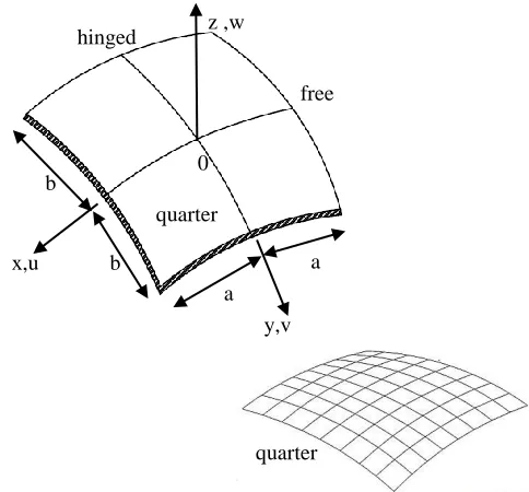
The suitability of the element for geometrical non-linear type of analysis was tested by using it in large deflection non-linear analysis of the hinged spherical panel with a central point load. The example was particularly chosen as other researchers have also used it to test their elements. The shell shown in the figure (4) is hinged along one of its parallel sides and free along the other edges. The dimensions and materials properties of the panel are given by a=b=254mm, R=2540 in both sides, E=3.103 kN/mm2, =0.3, t=25.4mm. R/t=100
0 0.5 1 1.5 2 2.5 3 3.5 4 4.5 5
16 36 64 100
V
e
rtic
al
D
isp
lace
me
n
t
[c
m]
Number of Elements
Present Ref. 20 Ref. 21 Exact Sol.
a 0
b x,u
b
z ,w
y,v a
Fig. 2. Spherical cap shell
a 0
b x,u
b
z ,w
y,v a
free hinged
quarter
quarter
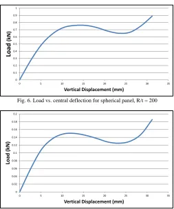
The results shown in figures 5 compare very well with those obtained from shallow strain rectangular element obtained from ref (19). The nonlinear behavior of the spherical has been also studied for the thickness values of, 12.7m and 6.35m, those give a radius to thickness (R/t) of, 200 and 400 respectively. (See figure 6 and 7)
Fig. 5. Load vs. central deflection for spherical panel, R/t = 100
Fig. 6. Load vs. central deflection for spherical panel, R/t = 200
Fig. 7. Load vs. central deflection for spherical panel, R/t = 400
5. CONCLUSION
A new spherical triangular shell finite element based on assumed strains has been successfully developed for the analysis of spherical shells. The element has been tested for a number of engineering problems, linear and nonlinear analysis of spherical panels problem were analyzed. The results obtained were compared with other available finite element solutions as well as theoretical results. A good rate of convergence and agreement with other solution was obtained.
In addition, the present element has the advantage of being simple in form and using only the five essential degrees of freedom makes it ready to assemble into structures made up of several components.
REFERENCES
[1] Grafton, P. E and Strome, D.R. (1963) “Analysis of ax symmetric shells by the direct stiffness metho ” AIAA. Vol 1.10, PP2342-2347.
[2] Jones, R.E and Strome, D.R (1966) “Direct stiffness method analysis of shells of revolution utilizing curved elements” AIAA J., Vol. 4, PP1519-1525.
[3] Brebbia, C and Connor, J.J. (1967) “Stiffness matrix for shallow rectangular shell element” J. Eng. Mech. Div. ASCE 93 EMS, pp43-65. [4] Cantin, G. and Clough, R.W. (1968) “A curved cylindrical shell finite
element”. AIAA Journal, Vol 6, PP1057-1062.
[5] Sabir, A.B. and lock, A.C (1972) “A curved cylindrical shell finite element”. Int. J. Mech. Sci. 14, P125.
[6] Cowper. G.R Lindberg. G.M and Olson, M.D. (1970) “A shallow shell finite element of triangular shape”. Int. J. solids and structures, Vol. 6, PP1133-1156.
[7] Yang, T.Y. (1973) “high order rectangular shallow shell finite element” J. Eng. Mech. Div. ASCE 99 EMI, P157.
[8] Dawe. D.J. (1975) “High order triangular finite element for shell analysis” Int. J. Solids Structures, Vol. 11, PP1097-1110.
[9] Ashwell, D.G. and Sabir. A.B. (1972) “A new cylindrical shell finite element based on simple independent strain functions”. Int. J. Mech. Sci., Vol. 14, _171-183.
[10] Sabir A.B. and Charchaechi, T.A. (1982) “Curve rectangular and general quadrilateral shell finite elements for cylindrical shells”. The Math. of Finite Element and Appli. IV Academic Press P231-239. [11] Sabir A.B and Ramadhani, F. (1985) “A shallow shell finite element for
general shell analysis” Variation Method In Engineering Proceedings of The 2nd International Conference, University of Southampton. England. [12] Sabir A.B and Djoudi, M.S. (1990) “A shallow shell triangular finite
element for the analysis of the analysis of hyperbolic parabolic shell roof”. FEMCAD, Struct. Eng. and Optimization, pp49-54.
[13] Sabir A.B. and El-Erris H. (1987) “Finite element analysis of hyperbolic paraboloid shells” Proc. Int. Cont. on non-conventional structures, London.
[14] Mousa, A.I (1998) “Finite element analysis of a gable roof” Computational Structural Engineering in Practice, Civil Comp. Press., pp 256-268.
[15] Mousa. A. I (2001) “Finite element analysis of groined vault cylindrical in plan” Al-Azhar Engineering Journal, Vol. 3, pp 37-50.
[16] Mousa, A. I and Sabir, A.B (1994) “Finite element analysis of fluted conical shell roof structures”. Computational Structural Engineering in Practice, Civil Comp. press-ISRN O-948 748-30x, PP 172-181. [17] Mousa, A.I et al (2012) “Non strain based cylindrical shell to analyse
cylindrical _” Canadian Journal of Environment, Constractions and Civil Eng., Canada.
[18] Mousa, A.I and Naggar, N.H (2007) “Shallow spherical shell rectangular finite element for analysis of cross-shaped shell roof” EJSE, Australia, Vol. 7, PP 41-52.
[19] Sabir, A.B and Djoudi, M.S (1997) “Large deflection geometrically nonlinear behaviour of spherical shells, UWCC Publication Internal Report. University of Wales, College of Cardiff U.K.
[20] Tahiani, C and Lachance, L. (1975) “Linear and non-linear analysis of thin shallow shells by mixed finite elements”. Computers and Structures, pp 167-177.
[21] Sabir A.B. (1997) “Strain based shallow spherical shell element” Proc. Int. Conf. on the Math. Finite elements and application, Brunel University.
0 1 2 3 4 5 6 7 8
0 5 10 15 20 25 30 35
Lo
ad
(kN)
Vertical Displacement (mm)
Ref. 19 Present element
0 0.1 0.2 0.3 0.4 0.5 0.6 0.7 0.8 0.9 1
0 5 10 15 20 25 30 35
Lo
ad
(kN)
Vertical Displacement (mm)
0 0.02 0.04 0.06 0.08 0.1 0.12 0.14 0.16 0.18 0.2
0 5 10 15 20 25 30 35
Lo
ad
(kN)