ISSN (e): 2250-3021, ISSN (p): 2278-8719
Vol. 08, Issue 6 (June. 2018), ||V (VI) || PP 72-82
Analysis Casting Simulation and Its Importance
Virendra Kumar, Barkat Ali and Nausad Khan
Delhi Institute of Technology and Management Research, Faridabad-MDU-Rohtak Correspondence: Virendra Kumar
Abstract:
Casting as a manufacturing process to make complex shapes of different materials in mass production may experience many different defects such as shrinkage porosity, sink, cavity and incomplete filling. For new castings or the castings having very high rejection rates, modification of feeding system design is of prime importance. A well designed feeding system is very important to ensure the better quality of castings. Design of feeding system also involves the decision about correct location of risers and number of risers to be used. Generally, gating system controls the velocity of molten metal that affects turbulence and flowability of casting. Solidification of metals stands as marvel of ultimate significance for metallurgists, casting engineers and physicist which hampers the quality of castings, material yield and cycle time. Casting defects are decreased through casting simulation software and an intellectual feeding technique.AUTO Cast (Demo) is casting simulation software which can simulate thermal changes and heat transfer in the solidification process of a casting. It assists the user to visualize the solidification process of a particular casting. The simulation software offers functions to help guide a user in producing gating and riser designs and also have functions which produce visual outputs showing possible problem areas and defects which may occur in a casting. It can help shorten the lead time and reduce the loss in the trial casting stage. Having demo version of AUTO Cast we have limited by designed gating system for cube. In present paper, an attempt is made to design the gating system with calculations and simulate solidification processes of the casting with the ANSYS.
Keywords
—Runner, Riser, Sprue , Sprue base, Gating System,Simulation--- Date of Submission: 11-06-2018 Date of acceptance: 26-06-2018
---I.
INTRODUCTION
Sand casting consists of placing a pattern (having the shape of the desired casting) in sand to make an imprint, incorporating a gating system, filling the resulting cavity with molten metal, allowing the metal to cool until it solidifies. Sand casting is still the most popular form of casting.
SAND CASTING PROCESS DESIGN
The typical sand casting process design consists of the following steps. 1) Sand Selection
2).Parting line 3).Pattern design 4).Core design
5).Gating/riser system design
CASTING SIMULATION SOFTWARE Usefulness:
Defects and problems can be discovered before the actual casting is cast avoiding costly tests to prevent the problems
Limitations
Casting simulation software cannot predict all types of defects that may occur in a casting, such as processing defects, human error, and additional chemical elements added to the molten metal, etc.
ANSYS
equation. Here, the used 2D model of the temperature field of the system is based on the numerical finite-element method.
II.
MODELING AND SIMULATION
Dimension of Pattern Area of the outer rim:
Outer diameter
A
1=
πd
2
4
=
π
¿
4
24
= 12.56
cm^2Inner diameter
A
2=
πd
2
4
=
π
¿
3
24
= 7.0685
cm^2Total area of rim A= A1-A2= 5.4975 cm^2
Volume of rim: V1= A*h = 5.4975*6= 32.985 cm^3
Area of the inner rim:
Outer diameter
A
3=
πd
2
4
=π
¿
3
24
= 7.0685
cm^2Inner diameter
A
4=
πd
2
4
=
π
¿
1
24
= 0.7853
cm
2
Total area of inner rim A= A3-A4 = 6.2831 cm^2
Volume of inner rim V2= A*h = 6.2831*3 = 18.8493 cm^3
Total volume of rim V = V1+V2 = 32.985+18.8493 = 51.8433 cm^3
Shrinkage of the Aluminum is added to casting
For aluminum, solidification shrinkage = 6.6%, solid contraction during cooling = 5.6%. Total volumetric contraction = (1-0.066)(1-0.056) = 0.8817
Linear contraction = (0.8817)0.333 = 0.9589 Final casting dimensions
Oversize factor for mold = (0.9589)-1 = 1.0428 Mold cavity dimensions: D = 4 .00(1.0428) = 4.1714 cm
Thickness t = 3(1.0428) = 3.128 cm
Core Design & Core Buoyancy Force: Core volume & weight:
ρcore= 1600 kg/m^3
Self-weight of large hole, WB1= π d^2* l *ρcore*9.81 / 4 = π *3^2*1.5*1600*(10^-6)*9.81/ 4
= 1.6642 N
Self-weight of small hole, WB2= π d^2* l *ρcore*9.81 / 4= π *1^2*3*1600*(10^-6)*9.81/ 4
= 0.3698 N Total self-weight of core, WB=WB1 + WB2
= 2*166.42+36.98 =0.36982 N
The buoyancy force B on the core B = π d^2* l*ρmetal/ 4 = π (2*3^2* 1.5+1^2*3)*2700*9.81*(10^-6)/ 4
=0.624085 N
The net force on the core (upward) = B – W
= 0.254265 N
Mold size:
Volume of casting= 51.8433 cm^3
60% of yield = 51.8433/.6 = 86.4055 cm^3
Weight of metal poured per mold = 60% of yield * Density of Aluminum =0.2332 kg
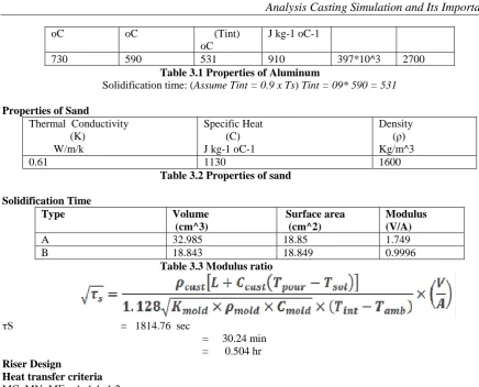
Properties of Aluminum
oC oC (Tint) oC
J kg-1 oC-1
730 590 531 910 397*10^3 2700
Table 3.1 Properties of Aluminum
Solidification time: (Assume Tint = 0.9 x Ts) Tint = 09* 590 = 531
Properties of Sand
Thermal Conductivity (K)
W/m/k
Specific Heat (C) J kg-1 oC-1
Density (ρ) Kg/m^3
0.61 1130 1600
Table 3.2 Properties of sand
Solidification Time Type Volume (cm^3) Surface area (cm^2) Modulus (V/A)
A 32.985 18.85 1.749
B 18.843 18.849 0.9996
Table 3.3 Modulus ratio
τS = 1814.76 sec
= 30.24 min = 0.504 hr
Riser Design
Heat transfer criteria
MC: MN: MF = 1: 1.1: 1.2
Where MF, MC and MN are modulus of feeder, modulus of casting, and modulus of the neck of feeder atthe junction of casting respectively.
Let Df = Diameter of feeder Hf = Height of feeder Assume Hf/Df = 1.5
Modulus of feeder = 1.2* modulus of region around hot tear = 1.2*1.75
= 2.1 Volume of feeder = π Df* Hf /4+π Df^2/4
= 1.75*π Df^2
Surface area of feeder = π Df^2* Hf /4
= 0.375*π Df^3
Modulus (V/A) = 0.214*Df
i.e 2.1 = 0.214*Df Df = 0.9813 cm
Hf = 1.472 cm Volume of hot spot region = 33 cm^3
Modified surface area of last freezing region
= surface area of hot spot – area of feeder bottom = 4.744 cm^2
Modified last freezing region = 5.5/4.744 = 1.159
Modified modulus of feeder = 1.2*1.159 = 1.3908 = 0.214*Df Df = 6.49 cm
Hf = 9.74 cm
Modulus of neck, Mn = 1.1*1.159 = 1.275 Neck height = 1 cm
Neck diameter = Dn Volume of neck = π Dn^2*Hn/4
Modulus, Mn = Dn/4 = 1.275 Neck diameter, Dn = 5.1
Feeder Yield and Efficiency
The riser efficiency depends on the feeder shape, type (open or blind) andapplication feed-aids, such as insulators or exothermic sleeves. It has to be consideredbecause the riser itself is also solidifying as it is feeding liquid metal to the casting. Foran open riser with a height per diameter ratio of 1.5, the efficiency is around 14 percent.It can be increased to about 50 percent if insulated with sleeves or exothermic sleeves.
Vol of casting, Vc = 51.84 cm^3 Vol of feeder, Vf = π Df^2*Hf/4 + π Dn^2*Hn/4
= 34.263 cm^3 Feeder Yield = Vc / (Vc+Vf)
= 60.21 % Shrinkage allowance, α = 3.16% = 0.0316
Feeder Efficiency = α *(Vc+Vf) /Vf
= 7.94%
Modulus of feeder insulated sleeve with modulus extension factor = 1.4 Modulus of insulated feeder = 1.2*1.159/1.4
= 0.9943 Modulus of feeder, Mf = 0.214*Df
Diameter of feeder, Df = 4.64 cm Height of feeder, Hf = 6.96 cm
Optimal Filling Time
A casting that fills too slow can have discontinuities such as cold shuts and misruns. Too fast filling can lead to solid and gaseous inclusions.
A generalized equation for filling time can be written as: Tf = K0 (Kf* Lf / 1000) (Ks + Kt t / 20) (Kw W)^p
There are five coefficients: K0 is an overall coefficient, and Kf, Ks , Kt, Kw are thecoefficients for fluidity, size, thickness and weight, respectively. For Aluminum thefollowing values may be used: K0 = 1.0, Kf= 1.0, Ks = 1.1 (for castings of size 100-1000mm), Kt= 1.4 (for wall thickness up to 10 mm), Kw = 1 and P = 0.4, Lf = 300 mm.
Total Weight of the casting, W = (Wt of casting + Wt of feeder)/ 0.9 = 0.2583 Kg
Tf = 7.893 sec
Gating System
The main objective of a gating system is to lead clean molten metal poured from ladle tothe casting cavity, ensuring smooth, uniform and complete filling.
Sprue
It is circular in cross section. It leads the molten metal from the pouring basin to the sprue well. Assuming Characteristic Loss Coefficient = Cf = 0.8
Inlet velocity (at parting plane), Vs = Cf*(2*g*H) H = Mold height + Pouring height
= 14+6 = 20 cm Vs = 1.584 m/sec
Gating ratio
Law of Continuity
The law of continuity states that the flow rate must be the same at agiven time in all portions of a fluid system. It may be written as:-
Q = A1V1 =A2V2
Where Q = metal flow rate in m^3/sec
A1 & A2 = cross-sectional area of flow channel at two differentpoints 1 & 2 in sq.cm V1 & V2 = metal velocity at points 1 & 2 in m/sec.
As: Ar: Ag = 1:2:1.5 As*Vs = Ag*Vg
Velocity at ingate, Vg = 1.584/1.5
= 1.056 m/sec
Choke Area and Velocity
The choke is the smallest cross-section in thegating system that controls the flow rate of molten metal. The element (sprue exit,runners or ingates) with the smallest value in the gating ratio is considered the choke. Thechoke area Ac is given by:
Ac = W / ( ρc* τf* Vc )
Where, W is the total casting weight (including feeders and gating channels), ρcis themetal density, τf is the total filling time and Vcis the choke velocity.
Ac = 1.088 cm^2 The choke velocity is given by
Vc = Vp + cf √ (2 g H) Vc = 1.584 cm/sec
WhereH is the metallostatic pressure head, given by the vertical distance between theliquid level in pouring cup and the centerline of the choke. The value of pouring velocityVpis non-zero, if poured from a height or if bottom pouring ladles are used. The frictionfactor cfwithin the gating system depends on its geometry and surface finish, and rangesbetween 0.6-0.9.
Gating Design‐Sprue
Sprue top area, AST:
AST = (ASE x Vchoke)/ Vsprue top AST = 1.884 cm^2
Sprue top diameter, DST:
AST = (π/4) x (DST)^2 DST = 15.5 mm Sprue exit diameter, DSE:
ASE = (π/4) x (DSE)^2 DSE = 11.77 mm
Runner
The main function of the runner is to slow down the molten metal, which speedsup during its free fall through the sprue, and take it to all the ingates. Runner Design
Assume Runner having width/depth = 1.5, Runner area (AR) = 2.176 cm^2 Runner Width = 12.04 mm Runner Height = 18.06 mm
Ingate
The ingate leads the molten metal from the gating system to the mould cavity Assume gate having width/depth = 2,
Gate area (AG) = 1.632 cm^2 Gate Depth = 18.06 mm Gate Width = 9.03 mm
SIMULATION Preprocessing
The preprocessing process contains the following commands to create a finite element model. They areas follows
3. Defining Material Properties 4. Creating Model Geometries 5. Defining Meshing controls
6. Applying Boundary Conditions, loads
Model
Once the model has been created and subjected to various boundary conditions ANSYS solves the set of equations generated by Finite Element Model.
2D model of casting part
Defining Element and Options
Solid 55 2D model of part and mold after giving material properties
Defining Material Properties
Units Sand Al
Thermal Conduct.
(K)
Wm-1 oC-1
0.346 94 (liq) 238 (solid)
Density P
g cm-3 (mg cm-3 oC-1)
2.32(bulk) 1.520 (Mold)
2.385 (liq) 2.7 (solid)
Specific Heat (C)
J kg-1 oC-1
1816 1050 (liquid) 896 (solid) Heat of
Fusion
(HF) J kg-1
395440
Melt Temp
(Tm) oC
Expansion Coeff.
(α) 10-6* oC-1
22.2 23.9
Applying Boundary Conditions, loads
III.
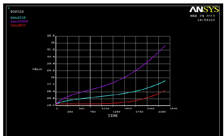
ANSYS RESULTS
Temperature distribution during solidification of casting to sand top,center and bottom w.r.t time
Heat loss from flywheel casting to surroundings w.r.t time
Plotting graph of Thermal conductivity versus Temperature of Aluminum
Temperature (
℃
)0 100 200 300 400 530 800
Thermal conductivity (W/m-°C)
206 208 215 228 249 268 290
Plotting graph of Enthalpy versus Temperature of Aluminum
H0 Hs Hl H
Temperature (
℃
)0 695 697 1000
Enthalpy (J/m^3)
0 1.6857E9 2 7614E9 3.6226E9
HEAT FLOW IN FLYWHEEL DURING SOLIDIFICATION
IV.
CONCLUSION
The objectives of this paper are fulfilled
1) Design the mold, gating/riser system for the circular Aluminum casting process and simulate the solidification of cube by Auto-cast software (demo)
2) Temperature distribution is shown in ANSYS i.e during solidification process
Casting Simulation is very powerful tool which is used to predict the growth of the process without physically performing the process. Solidification simulation provides iterative means of designing or modifying the feeding system. This reduces the overall cost of developing the method for new casting by minimizing the time as well as labor involved in it. Large number of trials can be performed quickly on simulation software package and optimum result can be obtained which ultimately increases the profit margin of foundry. Simulation also adds confidence to the methods engineer about the functionality of feeding system design.
REFERENCES
[1]. P. N. Rao, Manufacturing Technology (Volume-1), Tata McGrawHill, Second Edition, 2002. [2]. R. Wlodawer, Directional Solidification of Steel Castings, Pergamon Press, First Edition.
[3]. Ravi, B., ―Metal Casting – Computer Aided Design and Analysis‖, Prentice Hall of India Private Limited, New Delhi, 2005.
[4]. Aluminum casting technology, AmerFoundrymens Society, 1993
[5]. Kavička F., Štětina J.: A numerical model of heat transfer in a system a plate casting mold suroundings for optimization. Proceedings of the Conference of the ASME, Seattle