ISSN (Online): 2320-9364, ISSN (Print): 2320-9356
www.ijres.org Volume 4 Issue 10 ǁ October. 2016 ǁ PP. 68-80
A Hardware-Software Approach for Design and Control of
Mechatronics Devices
Ramon Barber
1, Cristina Castejon
2, Antonio Flores
1, Higinio Rubio
21(Robotics Lab. System Engineering and Automation Department. Universidad Carlos III de Madrid. Spain) 2
(MAQLAB.Mechanical Department. Universidad Carlos III de Madrid. Spain)
Abstract:
This paper presents an integration of hardware-software approach for the design and control in real time for mechatronicssystems using low cost hardware, but with high performance. The proposed tools allow both working without in production phaseas in simulation phase, being a useful tool for the design of mechatronics devices. For this purpose Rapid Control Prototypingusing a Model Based Design with high abstraction programming level capabilities have been used. This model provides to theuser a fast coding and testing environment and ensures a critical safety compliant low cost embedded controller, according to SILdirectives. For the software prototyping it has been used the developed tool and Simulink Code Generator, which is a tool widely usedin engineering which allows the integration with other design and analysis high level software. The developed blocks optimize thecode that is embedded in the controllers, improving the chances of microcontrollers compared to other solutions. As experimentalplatform a robotic prototype designed to the analysis of service robots have been used, which integrate design, analysis and controlphases. The proposed system allows to test the controller both in simulation and real hardware in a coordinate way. Validationtests are carried out in a robotic prototype designed to the analysis of service robots have been used, which integrate design,analysis and control phases.I
.INTRODUCTION
The development and design of robotics and mechatronics systems is a complex task and usually it requires very expensivecontrol hardware and very complex control software or something that might offer fewer possibilities for the research world.Further, it is an interdisciplinary task that includes design, building and control. For instance, for mechanics engineers isa complex task to work with control theory and with classical textual languages, without interdisciplinary tools such asSimulink®. For this purpose, a Rapid Control Prototyping (RCP) base tool is a good solution [1] [2]. Being able to implementa low cost hardware and software system, which is also easily integrate with commonly used software, would improve thedesign process and would reduce the development cycles of this type of robotics and mechatronics systems, which in mostcases are research prototypes.
Traditionally, the development of the embedded software, also called firmware, includes many processes such as choosing anddesigning the embedded controller, programming languages like C or assembly, the microcontroller unit (MCU) programming,running and testing the program as well as verifying its performance. All these embedded controller design stages need tobe restarted for each detected error or programming mismatch, and a great amount of work, time and knowledge neededfor text based programming [3]. Unfortunately, due to this fact, there are authors that consider that final implementation, thedeployment of their algorithms into an embedded controller, is out of their scope [4].
In the development of the embedded firmware that provides, data acquisition, data processing and full control of the system,a methodology based on the use of Rapid Control Prototyping (RCP) software/hardware tools is used. Using a RCP enables agreat set of interesting features, all mentioned in previous stages, for firmware development, that can be accomplished usingthe same unified software/hardware platform. The RPC makes possible many complete system tests and interactions in an earlydevelopment stage. Usually a RCP system provides a higher level of abstraction due to the use of graphical programminglanguages, which provides interfaces that allows to avoid the complexity of the management of analog and digital inputs andoutputs (I/O). This fact makes possible the use of a RCP system for a multidisciplinary audience [5], [6], allowing an easyintegration of multiple analog, digital and communication interfaces at the same time for a stand-alone controller.
that make up the platform are not exposed to damage, and the cost and time of experimentaccomplishment are considerably reduced. In [8] the main characteristics and peculiarities of service tasks are researched inorder to propose a design criteria in the form of computationally efficient object functions, which can be implemented ina multi-object optimization algorithm by using commercial packages in order to obtain optimal design solutions for servicerobots.Several robotics works are related to the idea that is tried to be implemented in this proposal, using CAD tools for developmentand SimMechanicsTM for robot control. In most cases these systems work either with only the simulator or only with the roboticplatform. In the case of [9] a robotic simulator for a complex robot is presented. In this case dynamic analysis are performed,incorporating a data perception registry mechanisms and allowing acting on the system but only by means of teleoperation.In [10] the system is designed using a CAD tool and then it is transferred to SimMechanicsTM. Tests were run with thesimulated robot but only in a later stage the results were applied to the real robot.
The main idea to this contribution is to incorporate control aspects in the design and control cycle of these prototypes usingRPC and model based design. The design and integration process of the robot using the designed tools, drastically reducesthe design-analysis control cycle of the robot, allowing its study to only take a few steps. Besides, including the robot’s directconnection in the control scheme allows switching, immediately and coordinately, between the simulation and the real robot. Finally, is a requirement for critical safety complaint controllers, ensures critical safety needed in services robotics,according to IEC 61508 and Safety Integrity Level 3/4 directives [11][12].
II. GENERAL OVERVIEW
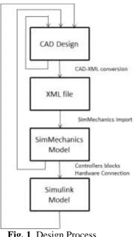
A. From design to control stepsAccording to the main idea presented in this paper, a design and control methodology is considered in the same loop, inorder to get efficiency for the full robot performance. In Figure 1, the design stages of the proposed system are shown. First,it starts with the CAD drawings of the robot, destined for its manufacturing. These drawings store all the information for therobot’s geometry and size, as well as the information needed for its assembly.
Fig. 1. Design Process
The design of the model, can be done with commercial a CAD tool like Inventor® and can be completed without the use of other more complex CAD design tools intended for kinematic and dynamic analysis. Within the CAD tool, some previous studies can be done, related to kinematics and static characteristics of the robot. In this paper, first studies about kinematics restrictions, mechanical stress analysis, and deformation analysis were carried. At this point, some re-designed can be established if changes are necessary in the initial design.
In Simulink® the model is completed with RPCs and control blocks that allow both testing control algorithms in the robot model as well as in the real robot through the generated code embedded in the control hardware generated by via the RPCs tool. At this point, first tests for the robot’s analysis and control can be carried out, obtaining the first results about for the robot performance. Whit these results, changing values in the initial design stage can be needed, being possible to adjust the design and parameters of the robot and its controllers in an easy way, until the final design of the robot is achieved.
B. Hardware-Software Architecture
Once the robot’s model is available in SimMechanicsTM and Simulink®, the next step is to search for
the hardware architecture that will enable the robot’s control. This hardware has the basic function to receive data from the encoder sensors, and send commands to the motors. As discussed in the introduction, a goal of this work is to make a coordinated control of the robot and the model in Simulink®. Furthermore, it should be the lowest possible cost, to make easier the construction and study of the robot prototypes. In an initial approximation, a scheme is proposed that allows to differentiate, on one hand, the visualization control and the management controller in a PC and, on the other hand, it considers a simple interface for the real robot, as shown in Figure 2.
Fig. 2.Integration controllers, hardware and simulation software
At first, the usage of a PC board link Delta-TAU PMAC has been discarded because of its costs and the complex way of programming and connecting it with Simulink®, increasing developing time. This board needs to be installed in a PC, linkingthe control system to that computer [13]. Other possibilities are the use of commercial DAQs, like ADVANTECH PCL-818C or KEITHLEY KUSB-3100 boards. It is an intermediate cost solution, but in the first case the card is attached to a specific computer again and the second one, connected via USB, which offers more possibilities in these aspects. Both solutions can be integrated with MATLAB® and Simulink®, but possibilities are reduced to some operations and it depends on the external mode of MATLAB®
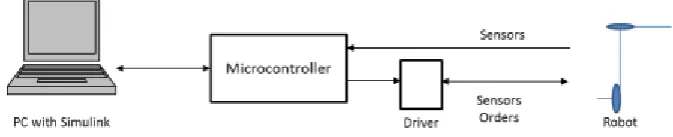
The proposed control architecture, after all the studies previously described, consists of a microcontroller based solution, that provides a low cost form of control and that can be integrated with a software design that allows the integration with MATLAB® and Simulink®. The architecture must be completed including the power amplifiers, and several solutions can be found. Figure 3 shows the general solution, in which the microcontroller is connected to a driver to move the robot and the data obtained from the sensors is used by the microcontroller to carry out the control through the computer and to the driver if they are needed for its internal controllers.
Fig. 3. Control layout using an external driver
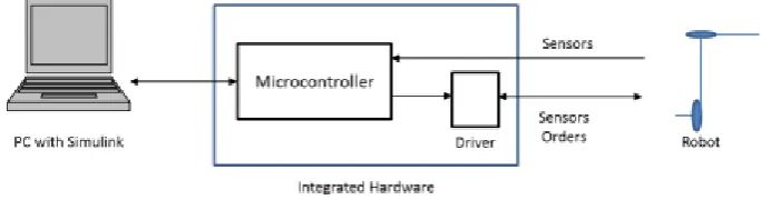
order to ease the full integration with the simulation and control models in Simulink®including SimMechanicsTM. In Figure 4 the proposed solution is shown, where the microcontroller and the driver are integrated and only control commands and sensor inputs are considered as interfaces for the full hardware-software controller.
This solution allows using the embedded controller as I/O device. The outputs are recorded in order to perform later a validation stage. In this case, safety does not rely only on software; it also relies on hardware implementation [12]. The embedded controller can be damaged either by a mechanical accident or due to electric problems. This situation needs to be taken into account to ensure entire system safety and reliability. Typically, the controller is optocoupled from the power stage that it is driving, but the power stage needs to detect if the controller is still working. Damaged controllers can still provide uncontrolled output signal to the power stage and this situation can be catastrophic. Not all the safety related aspects of the embedded software can act in a scenario like this one. To avoid this potentially dangerous situation, in a human-like scenario as the one used in this paper, the power stage is implemented with a controller keep alive signal detection circuitry. The signal controller presents its own complexity, because it needs to have a fixed frequency for the analogue output signal. This way, if the embedded controller is damage or a system failure occurs, the output failure can be avoid.
Fig. 4. Control layout with a hardware integration of the microcontroller and driver
III. HARDWARE-SOFTWARE INTEGRATION
A. Software generation toolThe described robot’s control system uses a 32-bit microcontroller (MCU) as independent control hardware. The PC can beused only to provide spatial position commands and desired speed or movement accuracy.
The RCP system used for this work presented in this paper has been developed in the RoboticsLab research group at UniversityCarlos III of Madrid [14]. Usage of any commercial available RCP system such as dSPACE, xPC Target [15], RT-Lab or NICompactRio/PXI ones, that represent most popular RCP systems for control automotive, industrial and aeronautics, requires aenormous investment that many researchers cannot afford. The RCP developed solution is based on a System-On-Chip (SOC)embedded system, that consist of a 32-Bit MCU running at 168Mhz (STM32F4xx from ST Microelectronics manufacturer),that provides plenty digital and analog interfaces requiring no external add-on hardware for most cases. The SOC RCP basedsolution proves itself to be the most competitive prototyping solution for both cost and performance [5], [16], [1]. Thecomputational power of the developed RCP system, a 32 bit MCU running at 168Hz with floating point support via hardware,is almost the double required for more than 50% of industrial production market ready control devices, that commonly requires16 - 32 bit MCU running at 10 - 99 Mhz with no floating point hardware support; and no more than 25% requires clockspeeds far beyond 100 MHz [17], [18]. These features, and the small footprint size and minimal power consumption, makesthe described RCP system appropriate for laboratory prototyping as well as for final hardware implementation, both stagesusing the same hardware, in a clear opposing position than many previously mentioned commercial RCP devices.
The high level of abstraction, for embedded software development on this described RCP system, is provided by theusage of MATLAB®/Simulink® that comes with a graphical programming language, ideal to develop control systems.MATLAB®/Simulink®programming environment is graphically based on simple appearance blocks that implement differentfeatures. Each block can be interpreted as a configurable modular piece of code. This block-set is completely tested anddebugged during its implementation, ensuring that bigger systems based on these modules will work without problems or hangups.
the commercial ones KeilUvision and IAR Ewarm.Several Blocks have been developed for the hardware interaction, such as analog and digital inputs/outputs, USB, CAN bus,Bluetooth, speaker and displays among others.
Fig. 5.Simulink®modeling flowchart using the UC3M RCP system. From left to right, Simulink®generates all the required source code for the selected compiler, and automatically loads the resulting firmware into the MCU
B. Hardware-Software Integration Blocks
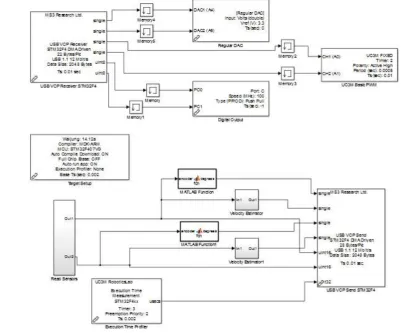
For the hardware integration, a Simulink®model must be created to program the microcontroller with the RPC tool. Thismodel contains blocks related to I/O of the system, the communication interfaces with the control model of the robot, and otherhardware issues. Figure 6 shows these blocks. Inputs and outputs of the microcontroller are connected to the control model of the robot via USB. The input blocks include readings from the encoders and blocks to calculate its value in degrees. The output blocks include PWM signals and analog signals to do the control of the DC motors of the robot. This chart includes the USB interface of the microcontroller between the computer and Simulink®, and the physical ports that connect with the drivers and sensors and actuators of the robot. Microcontroller works in real time, so a clock block has been added to the model. Finally, for the RPC tool the model needs to contain a Target Setup block, represented in Figure 6 as Target Setup. This block specifies to the code generation process the hardware architecture and other related stuff, such as MISRA C complaint features, in order to generate and compile a program suitable for the selected embedded controller. When the model with the hardware interfaces is finished, the software is automatically transferred to the microcontroller.
Once the microcontroller is ready, the client model, that is, the model of the mechatronic system with the controllers, needs to be modified with the blocks and software that connects to the software previously embedded in the microcontroller. The mechatronic model, in this case imported from Simulink®and SimMechanicsTMis completed with the blocks of Simulink®that connect to the hardware. In this case, a USB block that connects with the input/output blocks is added to the model. As input, signals can be read from the sensors of the system, such as, the encoders. As output, two control possibilities are ready to be used: analog outputs or PWM outputs. A digital output is enabled to define the direction of rotation, needed by some drivers. In Figure 7 the full control model including connection with the system model and to the hardware is shown.
Fig. 7.Simulink®control model with hardware connection
As an additional important issue, not used in this work, the Simulink®control model can be embedded in the microcontroller, allowing the use of the robot without the connection to the computer, as in operating conditions.
IV. APPLICATION EXAMPLE: 2 DOF ROBOT
In order to test the proposed methodology, a 2 DOF robot arm has been used, as robotic prototype. This robot has been built for the study of actuators dimensioning in the SIDEMAR project [19], granted to the Department of Systems and Automation Engineering and the Department of Mechanics Engineering of the University Carlos III of Madrid by the Ministry of Education and Science. The system is designed as a service robot, which according to the IFR (International Federation of Robotics) [20] is a robot operating partially or totally autonomously, to perform useful services for humans well-being and of equipment, excluding manufacturing operations, meaning, a system that cannot be used in the industry or to manufacture products. Moreover, today is an excellent platform for learning advanced robotics.
A. Robot’s Description
The SIDEMAR robot was created and designed as a general prototype that fulfills certain basic requirements that would allow its usage as a service robot. Its weight must be light but at the same time, it should be able to resist all the forces to which the robot can be subjected to when working. The experimental platform was designed to carry out kinematic studies, either direct or inverse kinematic and also for a good dynamic study.
Following the idea previously described, the material used to make the links was an aluminum alloy because it has a reduced weight compared to other structures available in the market and at the same time, a stiffness that eases the robot’s mechanical assembly, due to the fact that the aluminum is a sweet metallic structure that can be handled and operated easily.
For the description of the structure, the robot is divided in three important parts and these parts, assembled together, provide the final platform:
2. Lower link: Is a joint made up by 4 aluminum tubes joined on its ends by circular aluminum plates. Its lower end isdocked totally to the base where the DC motor is found and on its higher end the motor-harmonic drive set is found and it connects to the second link. As shown in Figure 8, the arm is made of an aluminum alloy but in a tubular structure instead of a solid one, in order to get a weight reduction and a modular and reconfigurable structure. Considering the first joint restrictions, this link will not be able to fully turn (360º), making more difficult the robot’s control tests. It is referred as Arm II in the tests.
3. Higher link: Just as the previous one, this joint is also made of an aluminum alloy structure and was built with a tubular structure to reduce the robot’s weight and make it modular. The link is docked to the harmonic drive located in the higher end of the first link and its other end is free. On this last end, most studies will be focused, because it shows the total scope of the robot and it would define its working area. It is referred as Arm I in the tests.
After the assembly of the three components (base, lower link and higher link) shown in Figure 8, an articulated system with2 DOF is obtained, with two rotation joints.
Fig. 8. SIDEMAR prototype
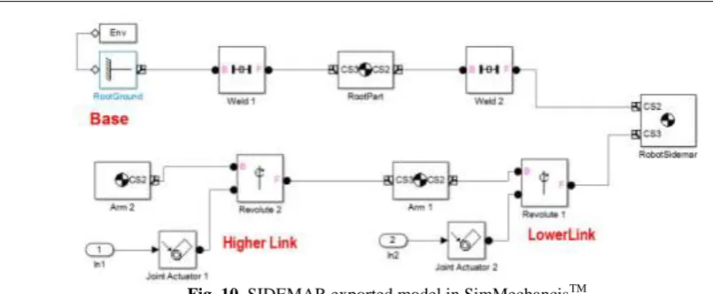
B. Robot’s Exported Model
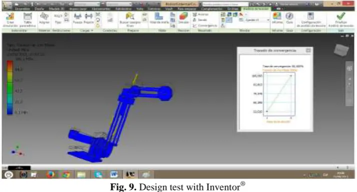
Following the steps mentioned in previous sections, showed in Figure 1, the CAD design has been developed in Inventor®After exporting it to MATLAB® and Simulink®, several static and kinematic tests have been performed, in order to check that the size of the robot’s body and the kinematic restrictions have correct values. Figure 9 shows some results of the static structural analysis studied using Von-Misses criteria.
Fig. 9. Design test with Inventor®
Fig. 10. SIDEMAR exported model in SimMechancisTM
C. Robot’s Complete Control Model
Once the robot structure is completely defined in Simulink®, two kinds of blocks must be added: blocks related to control and blocks related to hardware.
1. Blocks Related To Control: The exported model contains only the robot’s mechanical model. At this point, the SimMechanicsTM model must be completed with SimMechanicsTM blocks for sensors and actuators, allowing to perform movements and sense the position of the model. Once the operation of the robot model has been tested, the following step is to add the controllers. In this case, a standard PID controller has been added, as shown in Figure 11, in order to control the position of each link.
Fig. 11.Simulink® model with control blocks
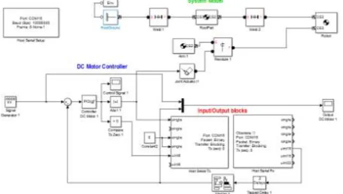
2. Blocks Related To Hardware: Once the model is working in a simulated mode, blocks that connect the simulation with the real robot need to be added. The complete model is shown in Figure 12.
The model of the robot is included in a sub-system block in order to clarify the diagram of the Simulink®model. Toconnect to the hardware, the model includes the blocks that connect the output signal from the controllers to the input of themicrocontroller via USB. In the same way, outputs from the microcontroller come from the USB connection in order to closethe control loop and monitoring the system. Besides, specific blocks are added to the position control. In this case, the outputsof the PID block is connected to DC motors through an analog signal ranging from 0 to 3.3 V, which is the working rangeof the I/O signals of the microcontroller. Finally, a zero crossing comparator produces a digital signal 0 or 1 to activate theswitch to change the motor rotation direction, connected to the reference signal-fault of the driver and get the reverse rotationof the motors. The model is completed with configuration block of the USB connection and other blocks like scopes for thereal robot.
V. EXPERIMENTAL RESULTS
To test performance of the full system, some tests with the robot must be accomplished. The goal of the first one is to ensure the correct performance of the models working with the simulation and the real hardware. The second one is a test of the control of the model of the robot. The third test consists on a control of the real robot and the last one is the simulator-robot coordination test.
A. Open Loop Test
The first test consists on tele-operating the robot and the simulation in a coordinated way. First tests were carried out with each of the arms separately and then, both arms moving at the same time, keeping both the simulation and the real robot coordinated.
Figure 13 shows, the real and simulated robot working coordinately, in which the robot and the simulation works in open loop, changing the values for signal generators to create control references and to test the operation in real time of the system.
Fig. 13. Open loop tests with simulation and real robot
B. Simulation Control Test
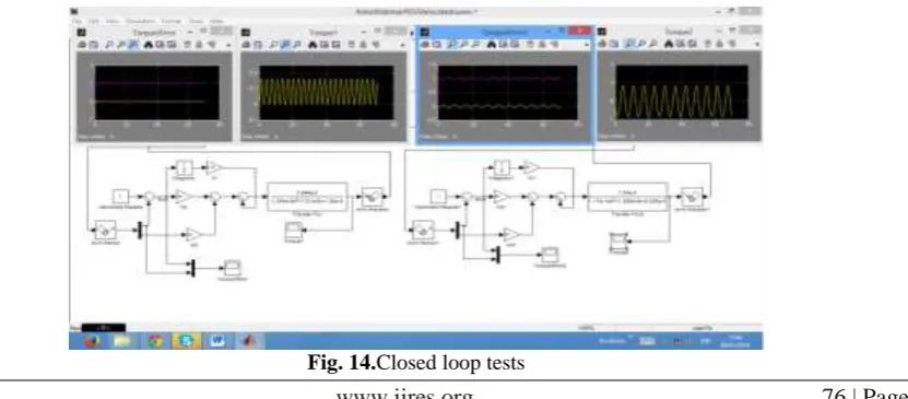
The simulation control test consists of trying an initial control scheme closing the control loop at the final positions of each arm and using a standard PID regulator as a controller. The tuning was carried out first on the simulation, in order to have a first estimation of the parameters of the controllers.
Figure 14 shows the model the full model of the robot working under control. Model of the robot is adjusted in this step, including the dynamic model of the motors and the motor-harmonic drive set. The scopes show the position response of both arms using sinusoidal input signals during the tuning of the controller.
C. Position Control Test of the Robot
The following test consists of closing the control loop with the position of each arm and using the PID regulator adjusted in the control simulation test. Using as a base this parameters, a fine tuning was performed empirically, until an acceptable.
System solution was reached. For the test, the upper arm, Arm I, change its reference 45 degrees in an horizontal plane. The Arm II, positioned in a vertical position, moves 45 degrees too.
Figure 15 shows the position response of both arms. In both cases the reference signal is reached by the robot. Arm II shows a slower answer because of the action of gravity.
Fig. 15.Position control results
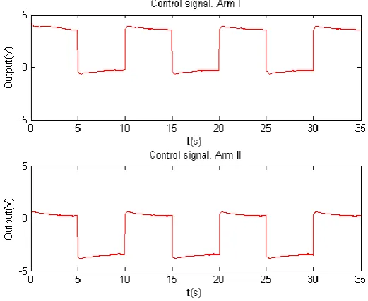
In Figure 16 the control signal for each motor is shown. The absolute value of the control signal is greater in movements against gravity.
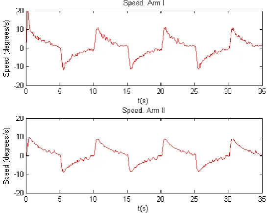
At last, the speed of both motors is shown in Figure 17. The speed properly evolves according to the reference changes.
Fig. 17. Speed control results
D. Coordinated tests Simulator-Robot
The two previous examples were used for coordinated testing. The first test consisted of an open chain control to check theeffectiveness of the connection simulated robot and the SIDEMAR robot. Afterwards, a second test will be run considering the first test results, using the same previously found values KP and Ki and checking the performance of both systems with the same control parameters.
The first test run for a coordinated system is to use the same open chain algorithm to test simultaneously on the robot’s model and on the robot itself. To accomplish this task the some tuning was needed to be carried out on the block diagrams, so that both could work with the same signals values and ranges.
As shown in Figure 12, a synchronize signal has been added to the model due to the fact that the SimMechanicsTM modelshared the input signal with the real hardware. Signal needs to be adapted to hardware levels using signals converters blocks.A synchronism problem, because the simulator could not work at the frequency required by the motors. To solve this problem,a condition block is added to allow to enable the simulation to work at 10 Hz and not at the frequency (100 Hz) required bythe hardware control.
In this last test the same PID control implemented in the previous sections will be used, using as reference signal thegenerator tuned in previous cases. The block diagram implemented used, as in the previous case, the separate signals sendingto the microcontroller and to the simulator.
Finally, the coordinated performance between the robot and the SimMechanicsTM model was obtained. Therefore, any testrun with the simulator can be applied to the real system connecting at the same time.
Fig. 18. Position sequences of the robot-simulation coordinated control
VI. CONCLUSIONS AND FUTURE IMPROVEMENTS
With the prosed hardware-software architecture, in few steps it allows to get from the design stage to the control one, reducing considerably the time of design and the time of analysis of the robot. The analysis and control of the robot is carried out using MATLAB®, Simulink®and SimMechanicsTM tools, widely used in industry for systems modeling and systems control. For the control system a low-cost hardware has been used, but in turn it has enough abilities to control the robot. As main component a STM32F4 microcontroller is used. The microcontroller is managed by libraries developed for its connection with the robot hardware, implemented with a developed Rapid Control Prototyping using a Model Based Design.
The use of the RCP system developed at UC3M RoboticsLab proves to be a great choice due to the quick integration of the entire system and ensures the critical safety of the system; thanks to the big quantity of embedded digital and analog interfaces as well as to the great computational resources, and the total software development via MATLAB®/Simulink®.
Experimental results show that it is possible to implement algorithms in embedded microcontrollers using the MATLAB®/Simulink®toolsto program and load the algorithm on it. Moreover, control actions are performed in real time on the physical system and simulation, being able to visualize their status and interacting with both physical system and simulation in a coordinated way.
REFERENCES
[1]. A. Flores, D. Copaci, A. Martin, D. Blanco, and L. Moreno. Smooth and accurate control of multiple shape memory alloys based actuators via low cost embedded hardware. IROS 2012.
[2]. A. Flores, D. Copaci, D. Blanco, L. Moreno, J. Herrn, I. Fernandez, E. Ochoteco, G. Cabañero and H. Grande Innovative Pressure Sensor Platform and Its Integration with an End-User Application, vol. 14, no. 6, pp 10273-10291, 2014.
[3]. J. Jang, C. K. Ahn, S. Han, and W. H. Kwon. Rapid Control Prototyping for Robot Soccer System using SIMTool. Proc. SICE-ICASE International Joint Conference, Busan, Korea, vol. 2, pp. 3035-3039, 2006.
[4]. E. Alexandre, L. Cuadra, L. lvarez, M. Rosa-Zurera and F. Lopez-Ferreras, Two-layer automatic sound classification system for conversation enhancement in hearing aids, in: Integrated Computer-Aided Engineering 15, ed., IOS Press, pp. 85-94, 2008.
[5]. X. Chen, X. Gong, H. Zhou, Z. Xu, Y. Xu, and C. Kang. An economical rapid control prototyping system design with Matlab/Simulink and TMS320F2812 DSP. IMECS, 2010.
[6]. G. Chindris and M. Muresan. Deploying Simulink models into system on-chip structures. ISSE 2006, pp. 313-317, 2006.
[7]. C. Castejon, D. Blanco, S.H. Kadhim, L. Moreno, Predesign of an anthropomorphic lightweight manipulator, Climbing and Walking Robots, Springer Berlin Heidelberg, pp 551-558, 2006.
[8]. C. Castejon, G. Carbone, J.C. Garcia Prada and M. Ceccarelli, A Multi-Objective Optimization of a Robotic Arm for Service Tasks, StrojniskiVestnik - Journal of Mechanical Engineering, vol. 5, pp 316-329, 2010.
[9]. D. Teodoro, Humanoid Robot Development of a Simulation Environment of an Entertainment Humanoid Robot. UniversidadeTecnica de Lisboa, September2007.
[10]. E. Aglav, A Snake-Like Robot for Searching, Cleaning Passages From Debris and Dragging Victims. The Graduate School of Natural and Applied Science of The Middle East Technical University, November de 2006.
[11]. M. Catelani, L. Ciani, M. Mugnaini, V.L. Scarano and R. Singuaroli, Definition of safety levels and performances of safety: applications for an electronic equipment used on rolling stone in: IEEE instrumentation and measurement technology conference, 2007.
[12]. M.A. Lundteigen and M. Rausand, Assesment of hardware safety integrity requirements, in: Proceedings on the 30th ESReDA seminar, 2006.
[13]. L. Xiangquan, Y. Chao, Z. Zhiqiang, C. Xinyi, N. Fengyan, Z. Jiyuan, Development of Mixed-connection Stacking Robot Based on PMAC, Computer Science and Information Technology, 2008. ICCSIT ’08. International Conference on, pp.362-366, 2008.
[14]. A. Flores-Caballero, Advanced rapid control prototyping system for exoskeletons and mechatronic devices, Phd. Thesis, Universidad Carlos III de Madrid, 2014.
[15]. O. Pinzon-Ardila, L. Angel, and M. Useche. xPC target an option for position control of robotic manipulators. LARC 2011, pp. 1-6, 2011.
[16]. D. Hcrcog, A. Kapun, and K. Jezernik. Implementation and usage of a freely available real-time operating system on an embedded robot controller. ElektrotehVestn (Slovenia), vol. 75, no. 3, pp. 136-142, INSPEC:10568924. [Online]. Available: http://ev.fe.uni-lj.si/3-2008/Hercog.pdf, 2008.
[17]. EE Times Group. 2011 embedded market study. TechnicalReport, 2011. [18]. EE Times Group. 2013 embedded market study. TechnicalReport, 2013.
[19]. C. Castejon, A. Gimenez, A. Jardon, H. Rubio, J. C. Garcia-Prada, C. Balaguer, Integrated system of assisted mechatronic design for oriented computer to automatic optimizing of structure of service robots (SIDEMAR), Climbing and Walking Robots, pp 327-334, 2006.