Throughput Estimates for A-MPDU and Block
ACK Schemes Using HT-PHY Layer
Teuku Yuliar Arif
Electrical Engineering Department, Faculty of Engineering, Syiah Kuala University, Banda Aceh, Indonesia Email: [email protected]
Riri Fitri Sari
Electrical Engineering Department, Faculty of Engineering, University of Indonesia, Depok, Indonesia Email: [email protected]
Abstract— IEEE 802.11n standard has introduced the new schemes in MAC and HT-PHY layers to improve network throughput. The new schemes in MAC layer are A-MSDU, A-MPDU and Block ACK. In the HT-PHY layer there are MIMO transmission using up to 4 spatial streams, 40 MHz bandwidth channel and 400 ns guard interval. In this paper, we proposed an analytical model that can be used to estimates the throughput of A-MPDU and Block ACK schemes using HT-PHY layer. In our model, there are six different slot types, which are A-MPDU transmission slot, A-MPDU collision slot, A-MPDU sub-frame error slot, BAR error slot and BA error slot. We derive the equations that can be used to calculate the time duration and the probability occurrences of each type slot. Our analytical model also considers the anomalous slot phenomenon in EDCA scheme and frame error probability in HT-PHY. The simulation results using matlab show our analytical model can be used to estimates the throughput of MSDU transmission using MPDU and Block ACK schemes. A-MPDU and Block ACK schemes can be used to improve the MAC throughput especially for MSDU size is bigger than 400 bytes.
Index Terms—Throughput, A-MPDU, Block ACK, HT-PHY, IEEE 802.11n
I. INTRODUCTION
WLAN IEEE 802.11 has developed rapidly, and it has attracted many researchers and industries. The results of the researches have created new enhancement and its have been adopted to standard IEEE 802.11 [1]. Among others developments that have been adopted are the increase of data rate in Physical (PHY) layer and provision of Quality of Service (QoS) mechanism in Medium Access Control (MAC) layer. The data rate of PHY layer up to 54 Mbps in 2.4 GHz and 5 GHz frequencies was based on the amendment of standard 802.11g [2] and 802.11a [3]. The last amendment to increase the data rate of PHY layer upto 600 Mbps using High Throughput (HT) PHY was introduced in standard IEEE 802.11n [4]. Meanwhile, the provision of QoS mechanism in MAC layer was adopted based on the IEEE 802.11e standard [5]. In the future, the data rate of PHY
layer is at least 1 Gbps using IEEE 802.11ac and IEEE 80211ad standard [6,7].
The main purpose of standard IEEE 802.11n amendment is to provide MAC Service Data Unit (MSDU) transmission throughput of at least 100 Mbps in destination Logical Link Control / Service Network Access Point (LLC/SNAP). The MAC layer of IEEE 802.11n provides Aggregate MSDU (A-MSDU), Aggregate MAC Protocol Data Unit (A-MPDU) and Block Acknowledgement (ACK) schemes to increase the throughput of MSDU transmission. Different from MSDU transmission using Distributed Coordination Fuction (DCF) channel access scheme, the amendment of standard IEEE 802.11n explains that MSDU transmission, which uses A-MSDU, A-MPDU and Block ACK schemes, is transmitted using Enhanced Distributed Channel Access (EDCA) scheme. To calculate and evaluate the throughput of MSDU transmission using A-MPDU and Block ACK schemes, an analytical model that can be used to predict the throughput of MAC layer in IEEE 802.11n accurately is needed.
In [8], we have proposed an analytical model that can be used to predict frame error probability in MSDU transmission using DCF scheme and HT-PHY layer. In other paper [9], we also have proposed an analytical model than can be used to estimates the throughput of A-MSDU transmission. In this paper we propose an analytical model that can be used to calculate the throughput of MSDU transmission using A-MPDU and Block ACK schemes in compliance with the amendments of standard IEEE 802.11n [4] and IEEE 802.11e [5]. In the same manner to the analytical model that we proposed in [9], we derive the analytical model of A-MPDU, and Block ACK throughput by calculating the effect of anomalous slot in EDCA scheme and the effect of bit error in HT-PHY layer.
Figure 1. Tinnirello’s DCF model with anomalous slot phenomenon
discussion are presented. In the last Section, which is Section 5, the conclusion and future work are presented.
II. RELATED WORK
Numerous papers have provided evaluation results of IEEE 802.11n aggregate frame schemes. Saif et al. [10] put forward the impact of the overhead used in the A-MSDU scheme to throughput and delay. However, the model that they proposed is not in compliance with the standard because it does not calculate the impact of the overhead of backoff process and also did not account the ACK frame calculations. Ginzburg et al. [11] proposed an analytical model that compares the performance of A-MSDU and A-MPDU schemes that carry TCP and UDP packets. However, they simplified the backoff process by using an average backoff interval, thus the channel utilization that they provided is inaccurate. Daldoul et al. [12] offered an analytical model to evaluate the impact of the frame aggregation to multicast traffic. Nevertheless, they also did not put into consideration the backoff overhead. Charfi et al. [13] suggested an analytical model to evaluate how frame aggregation affects real-time application. However, their analysis was not precise because contention based QoS, including enhanced distributed channel access (EDCA) with frame aggregation, is certainly not designed to provide QoS guarantee. The adaptive two level frame aggregation using A-MSDU and A-MPDU in IEEE 802.11n is shown in [14]. As the method to deal with delay penalties and increased packet error rate in frame aggregation scheme, G. Bhanage et al. [15] proposed a backlogged queue (BQ) aggregation approach.
Several other papers have provided evaluation of throughput in the MAC layer that is produced from using Block ACK scheme via an analytical model while utilizing a simulation. Faruqui et al. [16] and Cabral et al. [17] show the performance of Block ACK scheme throughput using simulation and implementation of testbed, but they do not provide an analytical model of a Block ACK scheme. Tinnirello et al. [18] and Liu et al. [19] developed a Block ACK scheme analytical model in the error free channel, as for Li et al. [20], Chen et al. [21] and Lee et al. [22], they have developed another analytical model of a Block ACK scheme in a noisy channel. But then again, the analytical models in [16]-[22] are not in accordance to the specification of [1] because they do not put into consideration the EDCA backoff overhead. Additionally, the Block ACK analytical models that they have proposed do not consider the use of frame aggregation scheme usage in 802.11n [5].
In this paper we propose an analytical model to evaluate the impact of using frame aggregation of A-MPDU and Block ACK schemes to the throughput of MAC layer in accordance to [4] and [5] specifications. Because the schemes were only utilized in QoS MAC layer, in this paper we have also used EDCA analytical model that we have derived in [9]. In our EDCA model, we use a contention zone approach in accordance to the framework of Han et al. [23]. However, the model that
we have derived considers anomalous slot issues as described by Tinnirello et al. in [24].
Tinnirello model used slot types same as Bianchi model [25] as shown in Fig. 1. Bianchi and Tinnirello modeled DCF scheme based on three different slot types. The slot types are idle slot, transmission slot, and collision slot. But unlike Bianchi model, transmission slot and collision slot in Tinnirello model has considered the anomalous slot phenomenon.
In the document of IEEE 802.11 standard, it is explained that when a wireless medium is busy in a slot time, the counter backoff values decrement is stopped. In other words, counter backoff decrement is only conducted when the slot is idle. The rule of backoff counter decrement at the end of time slot causes there is a slot after successful transmission only accessed by the last station (STA) who is transmitted the frame. This slot is called the anomalous slot.
Anomalous slot can also happen when the transmitted frame collides or experiences an error. If the transmitted frame by STA on a slot collides or experiences an error, the first slot after Extended Inter-frame Space (EIFS) duration cannot be used to transmit the frame by the last STA transmitting the frame or by any other STA which detects collision on channels.
In the EDCA model that we propose in [9], each type of slot in EDCA has different occurrence probability. We have calculated the probability of idle slot, probability of transmission slot, and probability of collision slot, using the same approach with [23]. However, [23] used the zone approach to calculate the transmission and collision probability in IEEE 802.11p. IEEE 802.11p has different CWmin, CWmax and AIFSN values than IEEE 802.11n. Therefore, zone contention between AC in IEEE 802.11n is different from the one in IEEE 802.11p. Another difference is the model [23] only calculates the frame damage caused by collision. In the EDCA model that we propose, we also calculate A-MPDU frame damage, which may be caused by bit error in HT-PHY layer.
III. A-MPDU AND BLOCK ACKSCHEME MODELLING
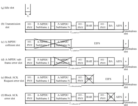
Figure 2. A-MPDU and Block ACK slot model
BAR and BA frame error are BAR and BA frame that are error due to bit error in HT-PHY layer.
Therefore, there are six different types of slots in A-MPDU transmission using EDCA and HT-PHY layer as shown in Fig. 2. They are idle slot, A-MPDU transmission slot, A-MPDU collision slot, A-MPDU sub-frame error slot, BAR error slot and BA error slot. The effect of anomalous slot in A-MPDU transmission is the presence of one additional slot after the duration of transmission slot, collision slot and error slot.
Each of slot type has different event probability. The probability of idle slot, transmission slot and collision slot can be calculated using Bianchi and Tinnirello analytical model [24, 25]. In our model, we also calculate the probability of A-MPDU error slot, the probability of BAR error slot and the probability of BA error slot. The probability of errors slot are calculated based on the bit error rate (BER) in HT-PHY layer.
A. Frame Error Probability (FEP)
The probability of a frame experiences corrupt or error depend on the probability of bit error in HT-PHY. A bit experiences error depend on the received signal level in HT-PHY receiver side. For the calculation of the probability of bit error to be more accurate, received signal level measured in the form of Signal to Interference and Noise Ratio (SINR).
Multiple Input Multiple Output-Orthogonal Frequency Division Multiplex (MIMO-OFDM) channel in HT-PHY IEEE 802.11n can be modeled as low fading channel toward frame duration; thus, it can be assumed that the channel condition is constant throughout the duration of a frame. Every OFDM subcarrier can be treated as Additive white Gaussian noise (AWGN) sub-channel with a constant SINR throughout frame duration. Signal vector subcarrier k received by receiver MIMO-OFDM can be expressed as follows [26]:
r( ) H( )T s( ) n( ) (1)
Where r(k) is N -element receive vector, H(k) is channel matrix MIMO, n(k) is N -element AWGN vector and T ∙ is the transformation of modulated vector symbol which represents spatial transmission process.
Output from the spatial reception process can be expressed as follows:
r(k) R r(k) s(k) n(k) (2)
SINR on subcarrier k from stream i is:
γ(k, i) F H(k), n(k) (3)
In the equation (3), function F ∙ is determined by the spatial process treatment toward transmitter and receiver where in IEEE 802.11n HT-PHY can take the form of spatial diversity, spatial multiplexing or beamforming.
The receiver reception can be measured as SINR per bit (notated as γ ) and average SINR per symbol (notated as γ ). When the receiver in HT-PHY receive signal that is modulated using BPSK, QPSK or M-QAM, the receiver then demodulates the signals into bit stream. Bit stream attained from the result of BPSK and QPSK signal demodulation has bit error probability as follows [27]:
P, (γ ) Q 2 ⋅ γ 12erfc γ (4)
In modulation M-QAM, k log M can be defined where k is the number of bit represented in one OFDM symbol which uses difference in phase and amplitude as M 2 . Error symbol probability modulated using M-QAM is:
P, (γ ) 1
1 2 ⋅ 1 1
√M
Q 3γ
M 1
(5)
Because γ k ∙ γ or γ k γ⁄ , bit stream attained from the M-QAM signal demodulation has bit error probability as follow:
P,
1 log M 1
1 2 ⋅ 1 1
√M
Q 3 ∙ γ ∙ log M
M 1
(6)
After bit stream is attained from demodulation process, bit stream will enter de-interleave and decoding process. De-interleave process does not affect the bit error probability because it merely changes the position of bit stream. Meanwhile the decoding process affects the bit error probability because it is measured based on the probability of some bits out of bits which experience error.
P, , (γ ) a P P, (γ ) (7)
If bit error is assumed to be distributed in uniform and independently on each data segment, bit error probability on data segment with L byte length is:
P , (γ , L) 1 P, , (γ ) ∙
(8) by measuring the bit error probability on all data segment, error packet probability is :
P 1 1 P , γ ,, L (9)
where n is the number of data segment, L is the segment length of a packet, mod is the modulation on segment i and γ , is the SINR per bit on segment i. It is worth noted that in one data segment, the average SINR value and the kind of modulation used is the same. However, for a different segment SINR and/or modulation used can be different.
If it is assumed that SINR is constant throughout MPDU frame transmission and ACK frame duration, each of the MPDU frame error and ACK FEP is:
P (γ , L )
1
1 P, , (γ ) ∙
P (γ , L )
1
1 P, , (γ ) ∙
(10)
Finally, total error packet probability on MPDU frame and ACK frame when transmitted through HT-PHY with N spatial stream can be measured as follows:
p 1 1 P ,
p 1 1 P ,
(11)
Probability of MPDU frame collision (p ) can be calculated using equation (7) in Tinnirello model [xx]. Finally, FEP in DCF scheme which is caused by MPDU collision, MPDU error and ACK error can be calculated using equation (13).
p p p p
p (12)
p 1 (1 p )(1 p ) (13)
B. A-MPDU Transmission Slot
The average duration of busy channel due to A-MPDU frame that is successfully transmitted and by taking into account the effect of anomalous slot can be calculated as follows:
(1⁄ )
1
(14)
in equation (14) is the duration of a successful A-MPDU transmission. In basic access transmission mode, can be calculated as follow:
(15)
is the overhead of HT-PHY layer. , and are the duration of A-MPDU, BAR and BA frames transmission times. They are dependent to Modulation and Coding Schemes (MCS) index and encoding type used in the HT-PHY layer. If BCC encoding is used, it can be calculated using the following equation:
(16)
(17)
(18)
is the length of A-MPDU frame can be calculated as follows:
( )
( 1) (19)
The maximum length of A-MPDU frame is 65535 bytes. is the length of an MPDU in an A-MDPU. The maximum length of an MPDU in an A-MPDU is 4095 bytes and the maximum number of MPDUs in an A-MPDU is 64.
C. A-MPDU Collision Slot
The average of channel in busy condition due to transmitted A-MPDU experiencing collision, by considering the effect of anomalous slot, can be calculated as follows:
(20) If the frame experiencing collision is transmitted using basic access mode, can be calculated as follow: (21)
D. A-MPDU Subframe Error Slot
The average duration of channel in busy condition caused by one or a number of A-MPDU sub-frames error can be calculated as follow:
(22)
E. BAR Error Slot
(23)
The average duration of channel in busy condition caused by BAR frame error, by taking into account the effect of anomalous slot can be calculated as follow:
(24)
F. Block ACK Error Slot
If transmitted A-MPDU frame is successfully accepted by STA receiver, but the BA frame received by STA transmitter is error, then the average duration of busy channel can be calculated equal to ; thus :
(25)
G. A-MPDU and Block ACK Throughput
MSDU throughput in an AC[i] transmitted using A-MPDU and Block ACK schemes can be calculated as follow:
∑ ∙ ∙ ∙
(26)
, , and each can be calculated using equation (10), (14), and (15) in [9]. is the number of MSDU bytes in A-MPDU frame successfully received by destination LLC/SNAP. If the BER condition is good, then all A-MPDU sub-frames with an MSDU or A-MSDU inside can be received well. However, if the BER condition is bad, then one or more A-MPDU sub-frames can be experiencing error. Thus, can be calculated using the number of MSDU bytes in A-MPDU sub-frame that is successfully received. The length of all MSDUs received by the receiver both in error and non-error A-MSDU sub-frames can be calculated as follow:
(27) If the bit error in HT-PHY layer is assumed as distributed uniformly in A-MPDU frame, the estimation of length that only has good A-MPDU sub-frame can be calculated as follows:
( )
(1
)
( ∙ )
(28)
where is the number of A-MPDU sub-frames that are damaged in an A-MPDU frame and is the total number of A-MPDU sub-frames in an A-MPDU frame. is the error probability of A-MPDU frame. Based on the calculation for bit error probability after demodulation and decoding process in HT-PHY, the error probability of an A-MPDU sub-frame can be calculated as follows:
( , )
1 1
, , ( )
∙ (29)
The probability of error A-MPDU sub-frame while transmitted through HT-PHY layer with spatial stream can be calculated as follows:
1 1 , (30)
If :
∆ ( )
(1
)
(31)
Thus, equation (28) to calculate can be simplified as:
∆
( ∙ )
(1 )
(32)
The average of MSDU total bytes in A-MPDU frame received correctly by the receiver in the same transmission slot, and by also considering the effect of anomalous slot can be calculated as follows:
(1⁄ )
1
(33)
The estimation of the duration of A-MPDU transmission using EDCA scheme, by also calculating the effect of A-MPDU sub-frame error, can be calculated as follows:
(34)
is the probability of a slot in EDCA scheme when idle, is the probability of A-MPDU to be transmitted, is the probability of A-MPDU to be damaged due to collision in the channel, is the probability of error of A-MPDU sub-frame, is the probability of error of BAR frame and is the probability of error of BA frame.
Γ 0 ( 1) Γ
( 1) Γ
(
1) Γ
(
1) Γ
(
1) Γ
(35)
The probability of A-MPDU sub-frame error can be calculated as follows:
(36)
in equation (34) is the error probability of BAR frame. The error probability of BAR frame can be calculated as follows:
( , ) 1
1 , , ( )
∙ (37)
The error probability of BAR frame transmitted through HT-PHY layer with spatial streams can be calculated as follows:
1 1 , (38)
The error probability of BAR frame in EDCA scheme can be calculated using the following equation:
(1 )
(39)
in equation (34) is the error probability of BA frame can be calculated as follows:
( , ) 1 1 , , ( )
∙
(40) The error probability of BA frame transmitted through HT-PHY with spatial stream can be calculated as follows:
1 1 , (41)
The error probability of BA frame in EDCA scheme can be calculated as follows:
(1 )
(1 )
(42)
The probability of A-MPDU frame to be successfully transmitted through HT-PHY layer using EDCA channel access can be calculated as follows:
(1 )
(1 )
(1 ) (1 )
(43)
The collision probability of A-MPDU frame in EDCA channel access can be calculated as follows:
1 (44)
IV. SIMULATION AND RESULT DISCUSSION
We use mathematical simulation to investigate how FEP performs on DCF scheme that is affected by the bit error in HT-PHY and inter-frame collision. We calculate FEP based on two variables, MSDU size and number of STA. In this paper, FEP in Bianchi and Tinnirello models are used to compare the proposed DCF model.
The simulation of FEP based on MSDU variable is arranged as follows. The minimum size of MSDU is 200 bytes and the maximum size is 2200 bytes. Before
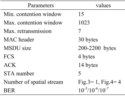
TABLE I.
SIMULATION PARAMETER FOR FIG. AND FIG.
Parameters values Min. contention window 15
Max. contention window 1023 Max. retransmission 7
MAC header 30 bytes
MSDU size 200-2200 bytes
FCS 4 bytes
ACK 14 bytes
STA number 5
Number of spatial stream Fig.3= 1, Fig.4= 4
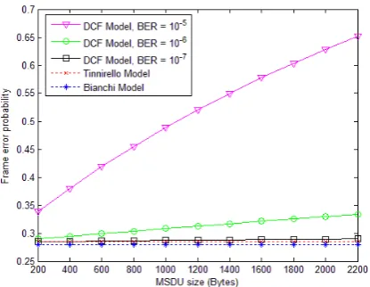
Figure 3. Frame error probability in different MSDU sizes ( 1)
Figure 4. Frame error probability in different MSDU sizes ( 4)
Figure 5. Frame error probability in different STA number ( 1)
Figure 6. Frame error probability in different STA number ( 4)
MSDU is sent to HT-PHY layer, 30 byte header MAC and 4 byte FCS will be added to MSDU to form an MPDU frame. Thus, FEP is calculated based on the length of the whole MPDU frame. On the receiver side, MPDU frame received will be responded by sending an ACK frame to STA transmitter. ACK frame can also experience error during transmission. Consequently, FEP is also measured based on the length of the whole ACK frame.
The effect of bit error and frame collision to FEP based on MSDU size is shown on Figure 3 and Figure 4; each shows FEP that can result when MSDU is transmitted using HT-PHY with 1 and 4 spatial streams. Table I shows the parameter that is used in simulation. The number of station in this simulation is 5 STAs. The simulation result shows that in MSDU transmission using 1 or 4 spatial streams, the FEP increases when BER condition increases.
Bianchi and Tinnirello models produce a different result. FEP by both models is constant if transmitted MSDU size increases. FEP of both models is also constant when transmission is with a different spatial stream number and BER condition. Thus, both Bianchi and Tinnirello models can only predict FEP based on inter-frame collision.
The effect of bit error in HT-PHY and frame collision to FEP based on the STA number is shown in Figure 5 and Figure 6. Table II shows the parameter that is used in simulation. Simulation result shows that in MSDU transmission using 1 and 4 spatial streams with the
TABLE II.
SIMULATION PARAMETER FOR FIG.5 AND FIG.6
Parameters values Min. contention window 15
Max. contention window 1023 Max. retransmission 7
MAC header 30 bytes
MSDU size 2200 bytes
FCS 4 bytes
ACK 14 bytes
STA number 5-50
Number of spatial stream Fig.5= 1, Fig.6= 4
Figure 7. Throughput of A-MPDU and Block ACK schemes in different MSDU sizes
Figure 8. Throughput of A-MPDU and Block ACK schemes in different STA number
number of STA competitor increasing, FEP will also increase.
Figure 5 shows FEP of DCF scheme on MSDU transmission using 1 spatial stream. The size of MSDU transmitted is 2200 bytes. Simulation result shows that if the number of competing STA and BER increases; FEP also increases. When the number of competing STA equal to 5, FEP equals to 0.4023, 0.2973 and 0.2858 for each BER equals to 10-5, 10-6 and 10-7. FEP will increase even higher when 1 spatial streams in HT-PHY layer is used to transmit MSDU with a higher number of STA. In MSDU transmission with the number of STAs equal to 50, FEP will be 0.6727, 0.6152 and 0.6089 for each BER equals to 10-5, 10-6 and 10-7. Bianchi and Tinnirello models each has FEP of 0.2799 and 0.2845 when the number of STAs equal to 5, and the FEP will increase to be 0.5787 and 0.6082 when the number of STAs equal to 50.
The Figure 6 shows FEP of DCF scheme in MSDU transmission using 4 spatial streams. When the number of competing STAs equal to 5, FEP equals to 0.6515, 0.3342 and 0.2896 for each BER equals to 10-5, 10-6 and 10-7. FEP will increase even higher when 3 spatial streams in HT-PHY layer is used to transmit MSDU with a higher number of STA. At the transmission of MSDU with the number of STAs equal to 50, FEP equals to 0.8092, 0.6354 and 0.6110 for each BER equals to 10-5, 10-6 and 10-7. Bianchi and Tinnirello models each has FEP when the number of STAs equal to 5 and the FEP when the number of STAs equal to 50 same as values in transmission using 1 spatial stream.
In this Section, we also use the mathematical simulation to analyze the analytical models of the A-MPDU scheme and the Block ACK scheme. We calculate
the MSDU throughput at destination LLC/SNAP transmitted using the A-MPDU scheme and the Block ACK scheme. The throughput is calculated based on the MSDU size transmitted and the number of STA. To shorten the simulation process and the result discussion, we only show the A-MPDU throughput transmitted by AC[0] having the highest transmission priority in the EDCA scheme. Then, we compare the throughput produced by the A-MPDU and Block ACK schemes with the A-MSDU scheme throughput so that the throughput increase using the A-MPDU and Block ACK schemes can be discovered.
The parameters used to simulate the A-MPDU and Block ACK schemes are shown in Table III. The MAC layer is assumed to continuously receive the MSDU from the LLC/SNAP sub-layer. Those MSDUs are then mapped in every suitable AC[i]. It is assumed that every AC[i] in the simulation used the default value of EDCA Parameter Set. Every AC[i] is also assumed using the A-MPDU and Block ACK schemes when transmitting MSDUs. Every MSDU existing in the transmission buffer of AC[i] is then added by 30 bytes of MAC header and 4 bytes of FCS to form the MPDU frame. Every MPDU frame formed is then added by 4 bytes of MPDU delimiter and 3 bytes of padding to form the A-MPDU sub-frame. Around 30 A-MPDU sub-frames are then aggregated to form one A-MPDU frame. The limitation of the A-MPDU sub-frames to around 30 in the
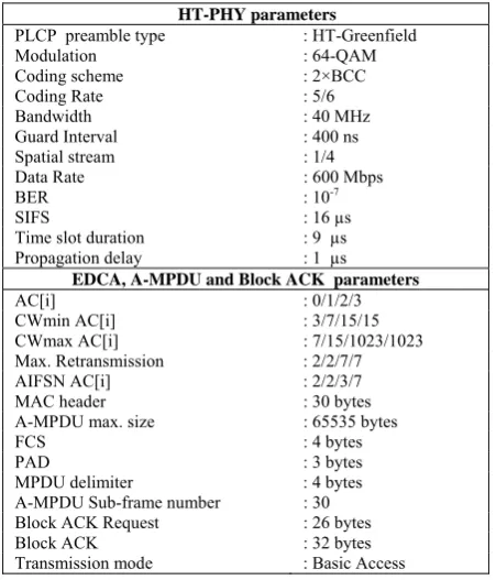
TABLE III.
SIMULATION PARAMETER FOR A-MPDU AND BLOCK ACK SCHEME
HT-PHY parameters
PLCP preamble type : HT-Greenfield
Modulation : 64-QAM
Coding scheme : 2×BCC
Coding Rate : 5/6
Bandwidth : 40 MHz
Guard Interval : 400 ns
Spatial stream : 1/4
Data Rate : 600 Mbps
BER : 10-7
SIFS : 16 µs
Time slot duration : 9 µs Propagation delay : 1 µs
EDCA, A-MPDU and Block ACK parameters
AC[i] : 0/1/2/3
CWmin AC[i] : 3/7/15/15
CWmax AC[i] : 7/15/1023/1023 Max. Retransmission : 2/2/7/7
AIFSN AC[i] : 2/2/3/7
MAC header : 30 bytes
A-MPDU max. size : 65535 bytes
FCS : 4 bytes
PAD : 3 bytes
MPDU delimiter : 4 bytes A-MPDU Sub-frame number : 30 Block ACK Request : 26 bytes
Block ACK : 32 bytes
simulation is done because the A-MPDU maximum length of 65535 bytes could only accommodate 30 MSDUs with the size of 2200 bytes. The A-MPDU frame is assumed to be transmitted using the basic access mode. In every transmission of A-MPDU frame, then the transmitter would transmit 26 bytes of the BAR frame to discover whether the A-MPDU sub-frame is received by the receiver without errors.
In the HT-PHY layer, the A-MPDU frame is added by the preamble of PLCP HT-Greenfield. The field of A-MPDU is coded using BCC with the coding rate 5/6. The A-MPDU bits coded and interleaved are then modulated using 64-QAM. The OFDM signal is transmitted using the bandwidth of 40 MHz. Among the OFDM symbols is the 400 ns guard interval inserted. HT-PHY is assumed using 4 spatial streams. If the 30 A-MPDU sub-frames managed to be received without errors in the receiver, the receiver further sent back the BA frame with the 32 bytes length.
Figure 7 shows the MSDU throughput performance at destination LLC/SNAP. The throughput is calculated based on the bit error probability after the demodulation and decoding process in the HT-PHY layer with the bit error probability variation of 10-5, 10-6, and 10-7. It is assumed that there are 5 STAs, all of which used the same parameter of HT-PHY and MAC as shown in Table III.
The simulation result shows the A-MPDU scheme can increase the MSDU transmission throughput, particularly the big-sized one. In the condition of BER= 10-7, the MSDU having the size of 2200 bytes if transmitted using the A-MSDU scheme only produces the throughput of 129.5 Mbps. However, if transmitted using the A-MPDU scheme, the throughput can increase to 279.7 Mbps. In the condition of BER = 10-6, the MSDU having the size of 2200 bytes if transmitted using the A-MSDU scheme only produces the throughput of 106.5 Mbps. However, if transmitted using the A-MPDU scheme, the throughput can increase to 243.1 Mbps. In the condition of BER = 10-5, the MSDU having the size of 2200 bytes if transmitted using the A-MSDU scheme only produces the throughput of 15.3 Mbps. Nevertheless, if transmitted using the A-MPDU scheme, the throughput can increase to 61.6 Mbps.
The small-sized MSDU transmission using the A-MPDU scheme does not significantly increases the throughput. The throughput of MSDU transmission with a smaller size than 400 bytes produces a lower throughput than the transmission using the A-MSDU scheme with the threshold of 7935 bytes. The A-MPDU scheme throughput decrease in the small-sized MSDU transmission is caused by the increase of MAC layer overhead, and the probability of the A-MPDU sub-frame experiencing errors also increases. The MAC layer overhead increase and the error frame probability in the A-MPDU sub-frame result in the decrease MSDU transmission throughput.
Figure 8 shows the MSDU throughput performance at destination LLC/SNAP transmitted using the A-MPDU and Block ACK schemes based on STA number increase.
The parameters of HT-PHY and QoS MAC used in the simulation are shown in Table III. The MSDU size transmitted is 2200 bytes. The A-MPDU and Block ACK scheme analytical model simulation result shows that the MSDU transmission throughput keeps decreasing when the number of STAs increased. The MSDU having the size of 2200 bytes is transmitted in the network with the number of STAs = 50, and the bit error rate of the HT-PHY layer BER = 10-7, so the throughput of the A-MPDU and Block ACK schemes decreases to 21.8 Mbps. In the condition of BER = 10-6 and BER = 10-5 each throughput decreases to 19.1 Mbps and 5.1 Mbps, respectively. The throughput decrease happens because the A-MPDU frame probability experiences the increasing collision when the STA number is raised.
V. CONCLUSSION
The IEEE 802.11n standard has introduced the MSDU transmission using A-MPDU and Block ACK scheme. In this paper we have derived the analitical model that can be used to estimates the throughput of A-MPDU and Block ACK scheme with HT-PHY layer. Our analitcal model consider the effect of anomalous slot and frame error probability. The simulation result shows the A-MPDU scheme can increase the MSDU delivery throughput, particularly the big-sized one. In the condition of BER equal to 10-7, the MSDU having the size of 2200 bytes if transmitted using the A-MSDU scheme only produces the throughput of 129.5 Mbps. However, if transmitted using the A-MPDU scheme, the throughput can increase to 279.7 Mbps. The small-sized MSDU transmission using the A-MPDU scheme does not significantly increases the throughput. The throughput of MSDU delivery with a smaller size than 400 bytes produces a lower throughput than the transmission using the A-MSDU scheme with the threshold of 7935 bytes. The A-MPDU scheme throughput decrease in the small-sized MSDU delivery is caused by the increase of MAC layer overhead, and the probability of the A-MPDU subframe experiencing errors also increases. The MAC layer overhead increase and the error frame probability in the A-MPDU subframe result in the decrease MSDU delivery throughput.
REFERENCES
[1] "IEEE Standard for Wireless LAN Medium Access Control (MAC) and Physical Layer (PHY) Specifications,"
IEEE Std 802.11-1997 , vol., no., pp.i-445, 1997.
[2] "IEEE Standard for Wireless LAN Medium Access Control (MAC) and Physical Layer (PHY) Specifications,"
IEEE Std 802.11g-2003 as amended by IEEE Stds 802.11a-1999, 802.11b-1999, 802.11b-1999/Cor 1-2001, and 802.11d-2001) , vol., no., pp.i-67, 2003.
[3] "IEEE Standard for Wireless LAN Medium Access Control (MAC) and Physical Layer (PHY) Specifications: High-Speed Physical Layer in the 5 GHz Band," IEEE Std 802.11a-1999 , vol., no., pp.i, 1999.
[4] "IEEE Standard for Wireless LAN Medium Access Control (MAC) and Physical Layer (PHY) Specifications Amendment 5: Enhancements for Higher Throughput,"
[5] "IEEE Standard for Wireless LAN Medium Access Control (MAC) and Physical Layer (PHY) Specifications Amendment 8: Medium Access Control (MAC) Quality of Service Enhancements," IEEE Std 802.11e-2005, vol., no.,
pp.0_1-189, 2005
[6] Vaughan-Nichols, Steven J.; , "Gigabit Wi-Fi Is on Its Way," Computer , vol.43, no.11, pp.11-14, Nov. 2010.
[7] Van Nee, R.; , "Breaking the Gigabit-per-second barrier with 802.11AC," Wireless Communications, IEEE , vol.18,
no.2, pp.4, April 2011.
[8] Arif, T.Y.; Sari, R.F., "Frame Error Estimation for DCF Scheme with HT-PHY Performance Evaluation," The 2013 International Conference on Internet Services Technology and Information Engineering (ISTIE 2013), 12-13 May.
2013.
[9] Arif, T.Y.; Sari, R.F., "An analytical model of A-MSDU scheme with enhanced Block ACK for IEEE 802.11n networks," Networks (ICON), 2012 18th IEEE International Conference on , vol., no., pp.291,298, 12-14
Dec. 2012.
[10]Saif, A.; Othman, M.; Subramaniam, S.; AbdulHamid, N.; , "Impact of aggregation headers on aggregating small MSDUs in 802.11n WLANs," Computer Applications and Industrial Electronics (ICCAIE), 2010 International Conference on , vol., no., pp.630-635, 5-8 Dec. 2010.
[11]Ginzburg, B.; Kesselman, A.; , "Performance analysis of A-MPDU and A-MSDU aggregation in IEEE 802.11n,"
Sarnoff Symposium, 2007 IEEE , vol., no., pp.1-5, April 30
2007-May 2 2007.
[12]Daldoul, Y.; Ahmed, T.; Meddour, D.; , "IEEE 802.11n aggregation performance study for the multicast," Wireless Days (WD), 2011 IFIP , vol., no., pp.1-6, 10-12 Oct. 2011.
[13]Charfi, E.; Chaari, L.; Kamoun, L.; , "Fairness of the IEEE 802.11n aggregation scheme for real time application in
unsaturated condition," Wireless and Mobile Networking Conference (WMNC), 2011 4th Joint IFIP, vol., no., pp.1-8,
26-28 Oct. 2011.
[14]Kim, Youngsoo; Monro, Edwin; Okhwan Lee; Kyung-Joon Park; Sunghyun Choi; , "Adaptive two-level frame aggregation in IEEE 802.11n WLAN," Communications (APCC), 2012 18th Asia-Pacific Conference on , vol., no.,
pp.658-663, 15-17 Oct. 2012.
[15]G. Bhanage, D. Raychaudhuri, I. Seskar, “Backlogged queue based MAC frame aggregation”, Pervasive and Mobile Computing, Volume 7, Issue 4, August 2011, Pages
449-466, ISSN 1574-1192.
[16]Faruqui, R.; Ghani, S.; , "A simulation study of Block Acknowledgements and TXOPs under varying channel conditions," Multitopic Conference, 2008. INMIC 2008. IEEE International , vol., no., pp.286-289, 23-24 Dec.
2008.
[17]Cabral, O.; Segarra, A.; Velez, F.J.; Mihovska, A.; Prasad, N.R.; , "Optimization of multi-service IEEE802.11e Block acknowledgement," Radio and Wireless Symposium, 2009. RWS '09. IEEE , vol., no., pp.380-383, 18-22 Jan. 2009.
[18]Tinnirello, I.; Sunghyun Choi; , "Efficiency analysis of burst transmissions with Block ACK in contention-based 802.11e WLANs," Communications, 2005. ICC 2005. 2005 IEEE International Conference on , vol.5, no., pp.
3455- 3460 Vol. 5, 16-20 May 2005.
[19]Liu, Wen-Jiunn; Huang, Chao-Hua; Feng, Kai-Ten; , "Performance Analysis of Block Acknowledgement Mechanisms for Next Generation Wireless Networks,"
Wireless Communications and Networking Conference (WCNC), 2010 IEEE , vol., no., pp.1-6, 18-21 April 2010.
[20]Li, T.; Ni, Q.; Turletti, T.; Xiao, Y.; , "Performance analysis of the IEEE 802.11e Block ACK scheme in a
noisy channel," Broadband Networks, 2005. BroadNets 2005. 2nd International Conference on , vol., no., pp. 511-
517 Vol. 1, 3-7 Oct. 2005.
[21]Ye Chen; Emeott, S.; Choudhury, R.R.; , "WLC24-6: An Analytical Model of Block Acknowledgement and Selective Retransmission in an 802.11e WLAN Network,"
Global Telecommunications Conference, 2006. GLOBECOM '06. IEEE , vol., no., pp.1-5, Nov. 27
2006-Dec. 1 2006.
[22]Hyewon Lee, Ilenia Tinnirello, Jeonggyun Yu, Sunghyun Choi, A performance analysis of Block ACK scheme for IEEE 802.11e networks, Computer Networks, Volume 54,
Issue 14, 6 October 2010, Pages 2468-2481, ISSN 1389-1286, 10.1016/j.comnet.2010.04.001.
[23]Chong Han; Dianati, M.; Tafazolli, R.; Kernchen, R.; Xuemin Shen; , "Analytical Study of the IEEE 802.11p MAC Sublayer in Vehicular Networks," Intelligent Transportation Systems, IEEE Transactions on, vol.13,
no.2, pp.873-886, June 2012
[24]Tinnirello, I.; Bianchi, G.; , "Rethinking the IEEE 802.11e EDCA Performance Modeling Methodology," Networking, IEEE/ACM Transactions on , vol.18, no.2, pp.540-553,
April 2010.
[25]Bianchi, G.; , "Performance analysis of the IEEE 802.11 distributed coordination function," Selected Areas in Communications, IEEE Journal on, vol.18, no.3,
pp.535-547, Mar 2000.
[26]Bjerke, B.A.; Ketchum, J.; Walton, R.; Nanda, S.; Medvedev, I.; Wallace, M.; Howard, S.; , "Packet error probability prediction for system level simulations MIMO-OFDM based 802.11n WLANs," Communications, 2005. ICC 2005. 2005 IEEE International Conference on , vol.4, no., pp. 2538- 2542 Vol. 4, 16-20 May 2005
[27]Andrea Goldsmith. Wireless Communications. Cambridge University Press, New York, NY, USA, 1st edition, 2005.
Teuku Yuliar Arif received the B.E.
degree from Sepuluh Nopember Institute of Technology (ITS), Surabaya, Indonesia, in 1998, and the M.Com., and Ph.D. degrees from University of Indonesia (UI), Indonesia, in 2004 and 2013 respectively. Since 1999, he joined Syiah Kuala University, Banda Aceh, Indonesia, as a lecturer at the Electrical Engineering Department. His research interests include wireless and mobile networks, vehicular ad hoc networks, and network performance analysis.
Riri Fitri Sari is a Professor