ISSN (e): 2250-3021, ISSN (p): 2278-8719
Vol. 07, Issue 12 (December. 2017), ||V1|| PP 42-46
Wireless Power Transmission: A Practical Approach and
Performance With “InTes Coil”
Harakh Jaydipkumar Trivedi
Abstract: The research work is based on the concept and performance with InTes Coil. The work is proposing a coil, “InTes”. The work also is a the practical approach with InTes Coil. The present concept is indicating the idea of wireless power transmission and performance with IntTes coil, the receiver coil and InTes coil is performing through wireless power transmission. The work is also indicating the idea of united working of Induction coil and Tesla Coil. Here the study is indicating larger EMF compare with particularly Tesla coil’s measured EMF and particularly Induction coil’s measured EMF. It is the new height and advance achievement of our propose InTes coil. The suggested InTes Coil of 1.5 KV is creating “electric resistance” in particular conductor compare with 1.5 KV of real Tesla coil’s “electric resistance” in conductor. Here’s is a Wireless power transmission with InTes coil and the performance with electromagnetic field. It is the suggestion of using wireless electricity for different objects of day today life. At the end the model is considering as eco friendly model which save environment and living being.
Keywords: Wireless Power Transmission, EMF
---
Date of Submission: 12-12-2017 Date of acceptance: 23-12-2017
---
I. INTRODUCTION
The work is initialing with the concept of wireless power transmission. The work is beginning with the development of “InTes” as transmitter coil using copper cable of 30 Gauge and 1.5 KV Empire input, and “Wireless Power Transmission” performing with Induction Transmitter coil. The present model is increasing EMF larger then particularly Tesla Coil and particular Induction Coil. It creates more electric resistance then creating electric resistance through Tesla coil individually and also creating more electric resistance through induction coil. Performance of InTes Coil have discussed with an identical work of the present research. Without out affecting environment and living being, the electricity is passing from ‘A’ side to side ‘B’, it means, transmitter coil is creating EMF field. It is based on the law of Mical Farady. Here very low frequency is using, so it is not affecting living creature and environment.
II. RESEARCH METHODOLOGY
The experimental research have used for the purpose of the present model. The data have obtained through based on practical work.
III LITERATURE REVIEW
IV WIRELESS POWER TRANSMISSION WITH “INTES COIL”
Fig. 1: InTes Coil without Induction Coil
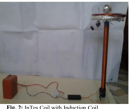
Fig. 2: InTes Coil with Induction Coil
The work is indicating propose and advance version of induction coil, it is “InTes Coil”. If we are using Induction Coil of copper cable and Tesla coil in united style or in combine approach with some identical change, it is producing wide range EMF. This result have obtained through practical work performed using certain copper coils with Maltimeter observation. It’s so happened, due to combined approach of “Induction Coil” and “Tesla Coil” with some identical change has taken. But, if in free style, if we keep the Tesla Coil individually and count the created EMF, It will have lower EMF. Furthermore, if we are making the sum of EMF created individually by alone Tesla coil and alone Induction coil, It will result in low range compare to newly proposed InTes Coil’s created EMF (A combine coil approach with identical change).
Proving With Equations:
Faraday’s Law of Electromagnetic Induction: The phenomenon in which electric current is induction in conduction by varying magnetic field is called electromagnetic induction.
As per this law.
EMF=by Changing a rate of magnetic flux respect to the time
Magnetic Flux
EMF
According to this equation, A changing magnetic flux in t Time is equal to a new generating EMF. As per the Faraday’s Law of Electromagnetic Induction:
Here, we are taking the changing rate of I for a t Time
Through the equation, data is parameterized.
In Tesla coil,
So that
In Induction coil,
With it, the study observed the difference of electrical resistance. Why resistance is increasing only due to EMF? While electricity is passing through a copper cable, the electron is interactive with molecule, so the coil is
creating resistance. So the rate of resistivity is called resistance. R is regarded as resistance, So is regarded as
resistivity.
There is so that
Here, Due to EMF, so the motion of the molecule is changing. It is affecting on electron. And ultimately the
resistance of copper cable is increasing.
Before the effect of EMF, the resistance of copper cable coil is.
=1.7× 10¯8
L = 7.4m
A= (0.00036) m2
Observation in tabulation expression:
No Item Observed in Tesla
Coil (Individual Approach)
Observed in Induction
coil (Individual
Approach)
Observed in “InTes Coil” (United Approach)
1 EMF (Electro
Magnetic Field)
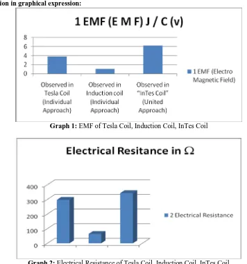
3.77928 (J/C)(v) 1.0223 (J/C)(v) 6.232587 (J/C)(v)
2 Electrical
Resistance
297 64 .82
Observation in graphical expression:
Graph 1: EMF of Tesla Coil, Induction Coil, InTes Coil
Graph 2: Electrical Resistance of Tesla Coil, Induction Coil, InTes Coil
V.HOW THE INTES COIL WORK
Put thetransmittercoil of solenoid induction where the highest flux creates on a Tesla Coil. As per the work
utilized equation, the obtained EMF of solenoid induction is 3.779258 J/C, and Telsa Coils EMF is 1.06223 J/C. Put the induction coil at a place where the highest EMF have obtained by Tesla Coil. Internal process occurred between Induction Coil and Tesla coil’s EMF. And adding these EMF created by Tesla Coil and Induction Coil. The obtained result or Sum of two different EMF is recognizing as Result 1.The EMF is transmitting through Tesla Coil so it is regarded as Transmitter coil. When we place induction coil at the place of Tesla coil where highest EMF created. The EMF of the Tesla coil working as conductor which convert the electricity. As per the law of electromagnetic induction, Due to changing electric current the conductor is creating electromagnetic waves. And that conductor is considering as an induction solenoid transmitter. So it is also creating EMF. And it is Result 2. We are combing Result 1 and Result 2, it is EMF of InTes Coil.
VI. DATA ANALYSIS AND RESULT
Table 1: Let us take the second item of the tabulation expression, the electrical resistance for only
Tesla coil and Induction coil is 297 and 64 . Where as in InTes Coil, It is observed as a
higher rate of 342.82, which is combine and united approach of two different coils (Tesla Coil and
Induction Coil).
Graph 1 : EMF of Tesla coil, Induction coil and InTes coil is instructing in the graphical expression of three different coil’s rate observation. In the same graph, the observation of InTes coil is found more
than 80cm, which is higher than first two coils.
Graph 2: Electrical Resistance of Tesla coil, Induction coil is 297, 64, which is depicted in graphical expression in graph 2, which are lower than the graphical expression found in InTes coil.
VII. CONCLUSION
Thus the work have completed with the expression of InTes coil. The work have observed that EMF and Electrical Resistance of Individual Tesla Coil and Individual induction coil is lower than InTes coil. Throughout present work, wireless power transmission is performed with two different coils and also perform with InTes coil. InTes coil is created by combining Tesla coil and Induction coil. Here, EMF and Electrical Resistance have observed and giving its expression into tabulated and graphical format. At the end the work indicating InTes coil is giving high performance of EMF and Electrical Resistance.
REFERENCE
[1]. Tesla.Nikola,”Apparatus For Transmitting Electrical Energy”, U.S Patent Number 1,119,732. November
1914.
[2]. Kripachariya Singh, S, “Wireless Transmission of Electrical Power of Recent Research & Development “
,IJCEE, Vol.No.2, April 2012.
[3]. Zhong. W, Kwan Lee. Chee, “Ron Hui S Y, “General Analysis on The Use of Tesla’s Resonators in
Domino Form for Wireless Power Transfer”, IEEE,Vol. 60, 1.Jan 2013.
[4]. Oliveira. S. C, Oliveira. E, Galdino J,”System Transmission Electrical Energy”, IRF International
Conference, 25 Jan, ISBN 978 -93-84209 -84 -1.
[5]. Prof. Burali Y.N, Prof. Patil C.B,”Wireless Electricity Transmission Based On Electromagnetic and
Resonance Magnetic Coupling”, IJOCER,Vol.2, Issue.7
[6]. Forman G,”An Extensive Empirical Study of Feature Selection Metrics for Text Classification”, JMLR 3
(2003)1289-1305.