Investigation of Shell and Tube Heat Exchanger
with Nano Fluid using ANSYS
V. Ajaykumar T. Sudhakar
PG Scholar Assistant Professor
Department of Thermal Engineering Department of Mechanical Engineering RVS College of Engineering and Technology, Coimbatore –
641402
RVS College of Engineering and Technology, Coimbatore – 641402
R. Titusjames U. Sathishkumar
Assistant Professor Assistant Professor
Department of Mechanical Engineering Department of Mechanical Engineering RVS College of Engineering and Technology, Coimbatore –
641402
RVS College of Engineering and Technology, Coimbatore – 641402
Abstract
The objective of this project is to analyze net heat transfer rate in shell and tube heat exchanger using nano particle suspended in different base fluids such as Water and Ethylene glycol. The thermophysical properties of naofluid mixture like density, thermal conductivity, specific heat, viscosity and density were predicted by analytical method. Then, the shell and tube heat exchanger using aluminium metal is created using CATIA and flow and thermal analysis is created using ANASYS.
Keywords: Shell And Tube HeX, Flow Rate,Al2O3 ANSYS14.5
________________________________________________________________________________________________________
I.
INTRODUCTION
Heat exchangers have a huge application in various industrial sectors such as oil refining, chemical industries, power plants and refrigeration units. Among the various types of heat exchangers, shell and tube heat exchangers are most widely used about 35-40%. The heat transfer rate of heat exchangers can be enhanced by two techniques active and passive methods. In this work, I am going to use one of the passive technique that is addition of nanoparticle to the working fluid.
II.
SELECTION OF MATERIAL
Aluminium
After iron, aluminium is now the second most widely used metal in the world. It is well known for its low density and for its ability to resist corrosion due to the phenomenon of passivation. It has tensile strength between 70 -100 Mpa. Unlike other metals aluminium doesn’t become brittle at low temperatures. But its strength decreases at temperature above 100oC. High thermal conductivity, Good corrosion resistance. High reflectivity, Less weight.
PROPERTY VALUES
Thermal conductivity 237 W/(m· K)
Melting point 933.47 K(660.32 °C, 1220.58 °F) Density 2.70 g/cm3
Nanofluid
Nanofluids are fluids that contain (1-100nm) sized particles. In order to enhance the thermal characteristics of convectional fluids, These nanoparticles are suspended in the base fluid by various techniques. Two-step is most commonly used for preparing nanofluid.
Base Fluid
Base fluids are convectional fluids that we used commonly in various industries. I have used the Water and Ethylene glycol as base fluids. The properties of base fluids are listed below,
PROPERTIES ETHYLENE GLYCOL WATER Thermal conductivity 995 w/m-k 995 kg/m3
Density 0.6280 kg/m3 0.6280 w/m-k
Viscosity 0.000657 0.000657
Nanoparticle
The nanoparticle choosed is,
AL2O3
Al2O3 is selected for the following work, there are two general classes of aluminas, the low surface area alpha alumina and high porous alumina. These later exist in several forms, of which are called gamma.
PROPERTIES VALUES
Type Alumina,gamma-Al2o3, purity:99%
Size 40-80 nm
Thermal conductivity 40 w/m.k Specific heat 765 J/Kg.K
Density 3970 Kg/m3
III.
ANALYTICAL CALCULATION FOR PROPERTIES OF NANOFLUID MIXTTURE
For calculating the properties of nanofluid the following formulas has been used. 1) Density can be calculated using mass balance equation
ρnf = (1 −φ) ρbf+φρp 2) Thermal conductivity
Knf = ((kp+ 2k0 + 2(kp − k0)ϕ)/(kp+ 2k0 − (kp − k0)ϕ)k0 3) Viscosity
ηr = ηbf(1+ 2.5)φ 4) Specific heat is calculated using energy balance
Cp=((1 − φ)ρbfcp, bf + φρp.p
Properties of Ethylene Glycol Based Nanofluid
Concentration Density Kg/m3 Specific heat J/Kg.K Thermal conductivity w/m.k Viscosity Kg/m-s 0.1 1103.86 2467.87 0.6297 0.009580 1.6 1146.90 2379.35 0.6572 0.009938 3 1187.07 2302.53 0.6835 0.010273 6 1273.14 2025.43 0.7424 0.010990
Properties of Water Based Nanofluid
Concentration Density Kg/m3 Specific heat J/Kg.K Thermal conductivity w/m.k Viscosity Kg/m-s 0.1 991.97 4164.44 0.6297 0.000599 1.6 1042.6 3970 0.6572 0.000621 3 1084.25 3803.1 0.6835 0.000642 6 1173.5 3329.93 0.7424 0.000687
IV.
DESIGN AND AND ANALYSIS
Design Datas
NUMBER OF TUBES 9 OUTSIDE DIA 0.015M
INSIDE DIA 0.0125M LENGTH OF TUBE 0.5M
BAFFLE THICKNESS 2mm HOT TUBE HEIGHT 50mm
HOT TUBE DIA 40mm
Calculation
BUNDLE DIA,
Db= do*3.93 =0.058M=58MM PITCH OF TUBES,
P= 1.25*do =0.01875m=18.75mm BAFFLE SPACING,
Bs= 0.8*Ds =0.08M=80MM PROVISIONAL AREA,
A= Nt*do*3.14*L =6*0.015*3.14*0.5==0.132 m2
Design
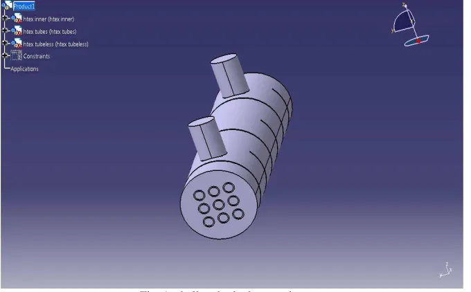
CATIA (Computer Aided Three-dimensional Interactive Application) started as an in house devolpment in 1977 by French aircraft manufacturer Avions Marcel Dassault, at that time it was used to develop Dassult’s Mirage fighter jet. CATIA offers a solution to facillate the design and manufacturing of routed systems including tubing, piping, heating, ventilating & air conditioning. In this work, CATIA V5 software is used to design the shell and tube heat exchanger.
Fig. 1: shell and tube heat exchanger
Analysis
Fig. 5: Mesh file
V.
FLOW ANALYSIS OF SHELL AND TUBE HEAT EXCHANGER
The flow analysis is carried by fixing static pressure condition and hot fluid inlet temperature 333k, cold fluid inlet 300k.
Fig .6: Flow model
In this task the flow model is provided with pressure based and gravity is neglected in this analysis. This figure clearly shows flow and temperature distribution.
Now Enable the required residuals and Set the Surface Monitors for Mass-flow rate and Exit-velocity to proceed to calculation.
Contour Plots For Water Based Al2o3 Nano Fluid
% Velocity Water based Al2o3 Ethylene glycol based Al2o3
1 0.05
1 0.08
1.6 0.03
1.6 0.05
1.6 0.08
3 0.03
3 0.08
6 0.03
6 0.05
6 0.08
VI.
RESULT AND DISCUSSION
From the results obtained from the anlaysis using ANSYS fluent, the net heat transfer rate is tabulated for water based al2o3 nanofluid mixture,
S.NO Concentration (%) Velocity (m/s) Net heat transfer rate (w)
Water based Al2O3 Ethylene glycol based Al2O3
1 0.1 0.03 18.25 10.49
2 0.1 0.05 21.04 18.44
3 0.1 0.08 22.45 21.30
4 1.6 0.03 20.9 16.83
5 1.6 0.05 22.81 21.62
6 1.6 0.08 24.93 23.42
7 3 0.03 29.30 18.06
8 3 0.05 31.09 22.47
9 3 0.08 33.50 27.94
10 6 0.03 30.74 21.16
11 6 0.05 32.01 25.49
12 6 0.08 37.41 29.89
Based on the results from the above table with increase in concentration and increase in velocity, the net heat heat transfer rate increases.
VII.
CONCLUSION
REFERENCES
[1] Arun Kumar Tiwari ‘thermal performance of shell and tube heat exchanger using nanofluid’, issn:2394-6202,(online):2394-6210,volume-1,issue-1,2015. [2] D.Mala, S. Sendhilnathan, A.Vembathu Rajesh,‘ Heat transfer analysis of al2o3 nanofluid in circular tube with two different twist inserts,’ Jchps special issue
5: 2015.
[3] M. Raja , R.M. Arunachalam and S. Suresh,‘Experimental studies on heat transfer of alumina /water nanofluid in a shell and tube heat exchanger with wire coil insert’, International Journal of Mechanical and Materials Engineering (IJMME), Vol. 7 (2012), No. 1, 16–23.
[4] Elena V Timofeeva*, Wenhua Yu,‘ Nanofluids for heat transfer: an engineering approach, a springer open journal.
[5] S. Bhanuteja1, D.Azad,‘thermal performance and flow analysis of nanofluids in a shell and tube heat exchanger,’ ISSN 0976 – 6359 (Online) Volume 4, Issue 5, September - October (2013), pp. 164-172.
[6] Ramesh *, Dr. R.Vivekananthan,‘ Application of Al2O3 Nanofluid for Enhance Heat Transfer Rate in Shell and Tube Heat Exchanger,’IOSR Journal of Mechanical and Civil Engineering (IOSR-JMCE) e-ISSN: 2278-1684,p-ISSN: 2320-334X, Volume 11, Issue 2 Ver. I (Mar- Apr. 2014), PP 29-33. [7] Design and rating of shell and tube heat exchangers by John E.Edwards, MNL 032A Issued 29 August 08, Prepared by J.E.Edwards of P & I Design Ltd,
Teesside.
[8] R.Dharun Arvind,‘ Heat Transfer Analysis Of Shell And Tube Heat Exchanger Using Aluminium Nitride - Water Nanofluid,’ International Journal on Applications in Mechanical and Production Engineering Volume 1: Issue 1: January 2015, pp 13-15.
[9] B.Jayachandriah, K. Rajasekhar,‘ Thermal Analysis of Tubular Heat Exchangers Using ANSYS,’ Volume No.3 Issue No: Special 1, pp: 21-25.