(www.dvpublication.com) Volume 2, Issue 2, 2017
11
ENHANCEMENT THE PERFORMANCE OF 64cm
2INTERDIGITATED FLOW CHANNEL OF PEM FUEL CELL BY
TAGUCHI METHOD
Dr. V. Lakshminarayanan
Department of Mechanical Engineering, BV Raju Institute of Technology, Narsapur, Telangana
Cite This Article: Dr. V. Lakshminarayanan, “Enhancement the Performance of
64cm2 Interdigitated Flow Channel of PEM Fuel Cell By Taguchi Method”, International Journal of Advanced Trends in Engineering and Technology, Volume 2, Issue 2, Page Number 11-15, 2017.
Abstract:
The Proton Exchange Membrane (PEM) fuel cell is an electrochemical device and its performance depends on the design and operating parameters. In this paper, optimization of various operating and design parameters on interdigitated flow channel with64cm2active area of the PEM fuel cell was considered. The modeling of Three Dimensional (3-D) PEM fuel cell, Analysis and optimization by Taguchi method was done by Creo Parametric 2.0, CFD Fluent 14.5and Minitab 17 software respectively. Based on the optimization study, the R: C- 1:2hasproduced 0.169 W/cm2 of power density on PEM fuel cell performance and square of response factor (R2) was achieved by Taguchi method as 99.93%.
KeyWords: Interdigitated Flow Channel,CFD,Taguchi Method,Optimization,Design and Operating
Parameters& PEM Fuel Cell.
1. Introduction:
The chemical energy of fuels (hydrogen and oxygen) is directlyconverting into electricity in Fuel cells without any intermediate stageslike classical combustion in the two and four stroke engine exhausting. The Proton Exchange Membrane (PEM) fuel cell is an environmentally friendly power source also it is suitable for powering both portable devices and mobile application due to their high energy density and lower operating temperature range [1]. The internal combustion engine can be replaced by PEMFC for transportation due to its high energy efficient, quick startup, quiet and clean. Since a PEMFC simultaneously involves electrochemical reactions, current distribution, water balance and heat transfer. The electrochemical reaction produces electricity along with byproducts of water and heat. Various flow channel designs have been used to obtain high current and peak power density, proper temperature distribution, and optimum water management. The influence of the flow channel path length on the PEMFC flow field design was addressed by Sukkee Um et al [2] and Shimpalee et al. [3]. The water management of PEM fuel cell has become an important task, because more water accumulation causes “flooding” or less water causes dryness of membrane can adversely affect the performance and lifetime of PEM fuel cells. Sukkee Um [4] revealed in his study that the water transport in PEMFC was discussed to show various water transport regimes, such as anode side water loss, cathode side flooding and the equilibrium condition of water at the channel outlets. Hence, the effects of the flow channel, membrane thickness, and inlet gas humidity are important to enhance the performance of PEM fuel cell. Identifying the proper flow channel and the flow field design is also of importance as they also affect the performance of the fuel cell significantly [5].
(www.dvpublication.com) Volume 2, Issue 2, 2017
12
design parameters for the performance of the PEM fuel cell. In this paper has a detailed study about the optimization of operating parameters like operating pressure, temperature, stoichiometric ratio of inlet reactant mass flow rate and design parameters like various rib to channel width (R:C)-1:1,1:2,2:1&2:2 on interdigitated flow channel of 64 cm2 active area of PEM fuel cell are to be studied and influence their performance are compared.
2. Model Development:
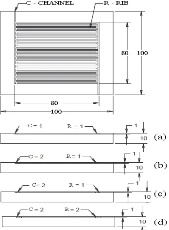
Three dimensional (3-D) PEM fuel cell model with interdigitated flow channel of various rib to channel width of 64 cm2 active area configurations were created by Creo Parametric 2.0 as shown in Fig.1.
Figure 1: VariousR: Cof (a)1:1 (b)1:2 (c)2:1 and (d)2:2 with interdigitated flow channel of 64 cm2 active area of PEM fuel cell
The modeling was done by creating all individual parts of the PEM fuel cell and the dimensions of individual parts such as the anode and cathode GDL, solid polymer electrolyte membrane, the anode and cathode catalyst layers as given below. The dimensions of fuel cell as mentioned below.
Anode & Cathode Flow field - 8cm x8cm x 1cm
Anode & Cathode catalyst - 8cm x8cm x 0.008 cm
GDL anode & cathode - 8cm x8cm x 0.0127cm
Membrane - 8cm x8cm x 0.03 cm
The Anode & Cathode Flow field has been assigned as solid zone type remaining parts has assigned as fluid type. After geometry modeling, the next step was discretization of PEM fuel cell done by ANSYS 14.5 ICEM software. The various geometrical models (R: C-1:1, 1:2, 2:1 and 2:2) of interdigitated flow channel were meshed by using ICEM 14.5 (a module of Ansys 14.5). The Cartesian grid meshing method was used, which is used in the formation of hexahedral mesh to attain accurate results. Split block method used for blocking. Body fitted mesh was used and projection factor was set to 1. The projection factor determines how closely the edges of the mesh match up with the grid.
2.1 Numerical Modeling: The simulation of PEM fuel cell was solved by simultaneous equations like conservation of mass, momentum, energy, species concentration, butler–Volmer equation, Joule heating reaction and the Nernst equation to obtain reaction kinetics. The model used to consider the system as 3-D, steady state and inlet gases as ideal condition, system as an isothermal and flow as laminar, fluid as incompressible, thermo physical properties as constant and the porous GDL, two catalyst layers and the membrane as an isotropic. A commercial solver (FLUENT software) based on control volume approach used to solve the various governing equations. Three-dimensional, double precision and serial processing were used for this model. The species concentration on anode side of H2, O2, and H2O were 0.8, 0, and 0.2 respectively.
Similar way, on the cathode side was 0, 0.2 and 0.1 respectively. The porosity at anode and cathode side was 0.5. Open circuit voltage was set at 0.95 V on the cathode and the anode was grounded. The cathode voltage has been varied from 0.05 V to 0.95 V used for solving kinetics reaction in order to get the current flux density, H2,
O2, and H2O fractions along with the flow field design. Multigrid settings were modified as F-Cycle for all the
equations and entered termination restriction value was set as 0.001 for H2, O2, H2O and water saturation. The
(www.dvpublication.com) Volume 2, Issue 2, 2017
13
concentration, Anode and cathode exchange coefficient was set to be 2. The Reference diffusivity of H2, O2 and
H2O was set to as 3E-5. Stabilization method BCGSTAB was selected for H2, O2, H2O, water saturation, electric
and proton potential. Optimization by Taguchi method was used to find out the most optimum combination among the input parameters which would result in getting the maximum possible output which cause the performance enhancement of PEM fuel cell. The standard orthogonal array of L16 with 4-level and 4-factors was used and the parameters were considered as low, high and medium range values. When L16 orthogonal array was used, significance of factors and optimum combination can be found in 16 runs itself. The theoretical value of hydrogen in the anode side was 4.33E-07 kg/s and oxygen in the cathode side was 3.33E-06 kg/s. The factors considered for the analysis were rib to channel width ratios on interdigitated flow field design (R: C-1:1, 1:2, 2:1 and 2:2), operating pressure (1, 1.5, 2 and 2.5 bar), temperature (313, 323, 333 and 343 K), anode and cathode reactants as stoichiometric ratios (S/F) of 3, 3.5, 4 and 4.5.
3. Results and Discussion:
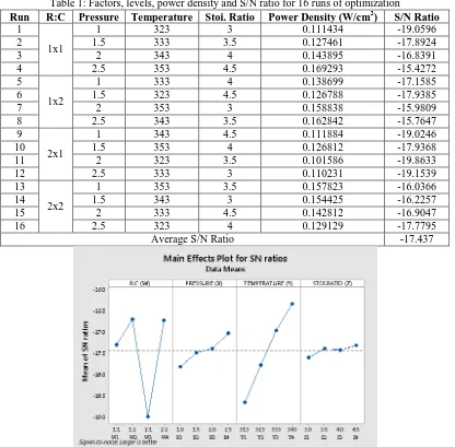
As per L16 orthogonal array, the optimized inputs were given to the Ansys CFD Fluent analysis software and considered all other parameters was constant. The power densities for all 16 runs, obtained from analysis software and the corresponding Signal/Noise (S/N) ratios were found from MINITAB 17 software itself as shown in the Table 1. The R: C - 1:1 of interdigitated flow field has shown maximum power densities of 0.169 W/cm2 and minimum power densities of 0.111 W/cm2respectively. Similarly the R: C- 1:2 and 2:1 having maximum power density of 0.162 W/cm2 and 0.126 W/cm2 respectively. The minimum power densities for the same R: C ratios have 0.126 W/cm2 and 0.101 W/cm2 respectively. For the rib to channel width ratio of 2:2 has shown maximum power density of 0.157 W/cm2 and power density of 0.129 W/cm2. The power output of PEM fuel cell must be maximized hence optimization was performed for “Larger the Better” type of Taguchi method. The S/N ratio plot for the same were obtained using Minitab 17 software and the corresponding maximum S/N ratio gives better performance as analyzed based on larger the better as shown in the Fig.2.
Table 1: Factors, levels, power density and S/N ratio for 16 runs of optimization
Run R:C Pressure Temperature Stoi. Ratio Power Density (W/cm2) S/N Ratio
1
1x1
1 323 3 0.111434 -19.0596
2 1.5 333 3.5 0.127461 -17.8924
3 2 343 4 0.143895 -16.8391
4 2.5 353 4.5 0.169293 -15.4272
5
1x2
1 333 4 0.138699 -17.1585
6 1.5 323 4.5 0.126788 -17.9385
7 2 353 3 0.158838 -15.9809
8 2.5 343 3.5 0.162842 -15.7647
9
2x1
1 343 4.5 0.111884 -19.0246
10 1.5 353 4 0.126812 -17.9368
11 2 323 3.5 0.101586 -19.8633
12 2.5 333 3 0.110231 -19.1539
13
2x2
1 353 3.5 0.157823 -16.0366
14 1.5 343 3 0.154425 -16.2257
15 2 333 4.5 0.142812 -16.9047
16 2.5 323 4 0.129129 -17.7795
Average S/N Ratio -17.437
(www.dvpublication.com) Volume 2, Issue 2, 2017
14
It was revealed from the Fig.3 that the design parameter likeR:Cof interdigitated flow channel having -1:2 as W2, and the operating parameters such like pressure - 2.5 bar mentioned as X4, temperature - 343 K noted as Y4, Stoichiometric ratio of inlet mass flow rate - 4.5 as Z4 were the optimum parameters to show the better performance of PEM fuel cell. Delta value of each factor available on the Minitab 17 software itself has been shown in Table 2. The optimization results of various parameters were based on S/N ratios and the significance of each factor by ranking them according to their performance. The factor with highest delta value indicates higher significance factor. It was found that operating temperature was the predominant factor affecting the performance of PEM fuel cell followed by rib to channel width (R:C) of interdigitated flow channel, operating pressure and stoichiometric ratio of inlet mass flow rate respectively. The percentage contribution of individual parameters on overall performance of the PEM fuel cell, P-test and F-test on the interdigitated flow fields has been shown in the Table 3.
Table 2: Delta and Rank for each level of factors
Factors Level 1 Level 2 Level 3 Level 4 Delta Rank
Rib to Channel width (R:C) -17.3 -16.71 -18.99 -16.74 2.28 2
Pressure (bar) -17.82 -17.5 -17.4 -17.03 0.79 3
Temperature (K) -18.66 -17.78 -16.96 -16.35 2.31 1
Stoi. Ratio -17.61 -17.39 -17.43 -17.32 0.28 4
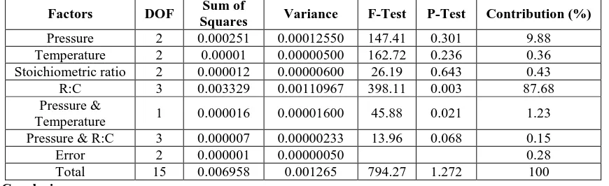
It was observed from the Table 3, rib to channel width ratio has been contributed to be 87.68 % , operating temperature was 9.88 %, the stoichiometric ratio of the reactants and R:C has contributed 0.43 % and 0.36 % respectively of the PEM fuel cell overall performance. Also the combined effect of combination of temperature with pressure and pressure with R:C has shown 1.23 % and 0.15 % respectively contributing to peak power performance of the PEM fuel cell.
Table 3: The individual parameters percentage contribution ofinterdigitated flow channel
Factors DOF Sum of
Squares Variance F-Test P-Test Contribution (%)
Pressure 2 0.000251 0.00012550 147.41 0.301 9.88
Temperature 2 0.00001 0.00000500 162.72 0.236 0.36
Stoichiometric ratio 2 0.000012 0.00000600 26.19 0.643 0.43
R:C 3 0.003329 0.00110967 398.11 0.003 87.68
Pressure &
Temperature 1 0.000016 0.00001600 45.88 0.021 1.23
Pressure & R:C 3 0.000007 0.00000233 13.96 0.068 0.15
Error 2 0.000001 0.00000050 0.28
Total 15 0.006958 0.001265 794.27 1.272 100
4. Conclusion:
Based on optimizing study of four different parameters, design parameter like R:C-1:2 ,operating parameters like operating pressure of 2.5 bar, temperature as 353 and stoichiometric ratio of inlet reactant gases as 4.5 exhibited 0.169 W/cm2 of maximum power density on interdigitated flow channel with 64 cm2 active area of PEM fuel cell and R2 value was arrived 99.93 %. The rib to channel width ratio has been contributed 87.68 % of overall performance of the PEM fuel cell. The combined effect of all the parameters exhibited a different response compared to their individual effects. The effect of operating and design parameters was affecting the performance of PEM fuel cell significantly.
5. References:
1. Maher, A.R., Sadiq Al-Baghdadi., “Three-dimensional computational fluid dynamics model of a tubular shaped PEM fuel cell”, Renewable Energy,33, 1334–1345, 2008.
2. Sukkee Um, C.Y., Wang and Chen, K.S., “Computational Fluid Dynamics Modeling of ProtonExchange Membrane Fuel Cells”, Journal of the Electrochemical Society, 147 (12), 4485-4493, 2000.
3. Shimpalee, S., Greenway, S., Van Zee, J. W. “The impact of channel path length on PEMFC flow-field design” Journal of Power Sources. 160, pp. 398-406, 2006.
4. Sukkee Um., Chao-Yang Wang., “Computational study of water transport in proton exchange membrane fuel cells”, Journal of Power Sources, 156, 211–223, 2006.
5. Andrew Higier and Hongtan Liu, “Effects of the difference in electrical resistance under the land and channel in a PEM fuel cell”, International Journal of Hydrogen Energy, Vol.36, pp. 1664-1670, 2011. 6. Yan WM, Chen CY, Mei SC, Soong CY & Chen F. “Effects of operating conditions on cell
(www.dvpublication.com) Volume 2, Issue 2, 2017
15
7. Lakshminarayanan V & Karthikeyan P. “Optimization of Flow Channel Design and Operating Parameters on Proton Exchange Membrane Fuel Cell Using Mat lab”, Periodica Polytechnica Chemical Engineering. Budapest Univ Technology Economics, 60, 3; 173-180, 2016.
8. Kanani H, Shams M, Hasheminasab M & Bozorgnezhad A , “Model development and optimization of operating conditions to maximize PEMFC performance by response surface methodology”, Energy Conversion and Management, vol. 93; 9-22, 2015.