111306-3838 IJMME-IJENS © December 2011 IJENS I J E N S
Dynamic Deflection of Periodic Cutting Tool Holder
Based on Passive Model
Yaser Hadi
([email protected])
Department of Mechanical Engineering, Yanbu Industrial College, Saudi Arabia
Abstract - Cutting force has a significant influence on the dimensional accuracy due to cutting tool-holder deflection. The problem of tool tool-holder deflection is faced frequently in a variety of engineering surface products, and to achieve this goal passive technique can be used. The need for passive technique arises from the complexities that brought to the structures by active control techniques and energy supplies required to implement such control systems. In this paper, an improved theoretical dynamic cutting force model for end milling is presented, using spectral finite element (FE) approach. The model depends on variable inputs such as, cutting tool shank diameter, number of periodic elements, choose the form of the cutting holder, if it is straight or periodic. The cutting parameters are given for getting an ideal cutting tool deflection distribution and frequency domain analysis. The simulation results indicate that the tool deflection has a significant influence on the dimensional accuracy of the finished part. The basic formulations of passive technique for deflection suppression of mechanical systems are briefly presented. It is based on the theory of dynamic deflection (proof mass -stiffness).
Keywords: Deflection, Periodic tool holder, cutting forces
I. INTRODUCTION
End milling is widely used in a variety of industries such as automotive, textile machinery and other manufacturing industries. In recent years, due to the need for improving the quality of parts, there has been a push toward decreasing the machine tool holder deflection in end milling. These deflections derive from the machine tool system and the
machining process. The errors of the machining process generated in face milling originate from a number of sources, but the tool system (cutter/holder) due to cutting force is one of the major problems for precision machining. For the cutting force prediction, Matlab model based on theoretical assumptions has been developed and reviewed by Smith and Tlusty [1]. The model illustrated the relationship between the deflection and the error on the machined surface. A few enhanced cutting force models have been developed in the last two decade [2-3, 7-9, 12-15].
111306-3838 IJMME-IJENS © December 2011 IJENS I J E N S
In this paper, an improved theoretical dynamic cutting force model of end mill is presented in section 2. A series of simulations are presented using aluminum raw material. The basic idea underlying the whole concept of periodic cells, that when a wave is travelling in a medium and meets a transition in that medium characteristic, a part of it will propagate through the new medium and another part will reflect into the old one. In regular straight cells, the wave expected to travel without any change until it reaches the boundaries of that structure, but when the structure change it its geometry and/or material properties to periodic cells, the occurrence waves will divide and condensed. To complete this work, a Matlab model introduced to clarify the key features in conjunction with finite element analysis (FEA) of flexible straight or periodic tool holder structures.
A part of the reflected wave will interact with the incident wave in a manner that will characterize the interference. When constructive interference occurs, the frequency is characterized by being the pass band of the structure, while, if they destructively interfere, the frequency is characterized by being the stop band of the structure. If the structure setup repeated for several times, it is known a periodic structure. The destructive effects will show more significantly, when the repetitions of the structure cell increase in number because as the part of the wave that propagates incorporates another similar changes in the medium, another part of it is destructed and so on.
In his paper, reviewing the research performed in the area of cutting tool holder system in periodic structures [16-22]. Mead [16] defined a periodic structure as a structure that consists fundamentally of a number of identical structural components that are joined together to form a continuous structure.
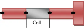
Examples of periodic structures can be seen in
fuselages of aircraft, petroleum pipe-lines,
railway tracks, and many others. An illustration
of a simple periodic bar is presented in figure 1.
FIGURE 1. An illustration of a simple periodic holder
In general, when a deflection in a holder structure encounters a change in the cutting tool geometry and/or the material properties, the vibration wave splits into two components; a propagating component and a reflected component. The reflected part interacts with the propagating part in a manner that decided by the phase difference between them. Studies of the characteristics of one-dimensional periodic structures have been extensively reported [17]. These structures are easy to analyze because of the simplicity of the geometry. Gupta [18] presented an analysis for periodically supported beams that introduced the concepts of the cell and the associated transfer matrix. Faulkner and Hong [19] presented a study of mono-coupled periodic systems. Their study analyzed the supported beams using analytical and finite element methods. Mead and Yaman [20] presented a study for the response of one-dimensional periodic structures subject to periodic loading. Mead [21] proved that the power transmission in both direction of a simply supported beam excited by a point force was equal regardless of the excitation location. Langley [22] proves the generalized supports an excitation force in the absence of damping generalized those results.
II. INSTANTENOUS DYNAMIC CUTTING
FORCES
The cutting forces cause a static deflection of the tool holder. Assuming the holder is rigid and perfectly has dynamic deflection according to the variation of the components of the tangential and radial forces caused, which varies during the total engagement with the workpiece. The undeformed chip thickness h carried by the flute at angular position can be derived as:
(
cos(
2
)
)
)
sin(
)
(
θ
R
f
Tθ
R
2f
T2θ
h
=
+
−
+
111306-3838 IJMME-IJENS © December 2011 IJENS I J E N S
In milling operation, as one of teeth is cut the next tooth following the cut will have a bigger chip load (feed per tooth) fT. For θS≤θ≤θE, where (θS) is the angle at which the cutter enters the cut and (θE) is the angle at which the cutter exits the cut. The angle at exit is approximately zeroed, (θE=0). The angular spacing between flutes on the cutter isγ, where
γ=360/T, where (T) is the number of cutting teeth.
The number of edges (M) that may cut
simultaneously is at the most as many as will enter into the span of the cutting engagement θC. θC=θE-θS plus the engagement of a tooth (ψ), which is obtained
as:
R
A
dtan(
β
)
ψ
=
Where
1
int
+
+
=
P CM
θ
ψ
θ
.Resolving the cutting forces in w and u directions:
cos( )
sin( )
wi Ti i Ri i
F
= −
F
θ
−
F
θ
sin( )
cos( )
ui Ti i Ri i
F
=
F
θ
−
F
θ
(2)
The instantaneous radial FR and tangential FT cutting forces acting on the tooth (i) is proportional to the axial depth (Ad) and chip thickness (h);
h
A
K
K
A
K
F
F
d R T d T R T
=
(3)Where, KT and KR are the instantaneous tangential and radial cutting force coefficients [23]. Substituting equations (2) and (3), rearranging the resulting expressions in matrix form yields:
h
A
K
K
A
K
F
F
d R T d T u w
−
−
−
=
θ
θ
θ
θ
cos
sin
sin
cos
(4)In multi-tooth end milling, if several teeth are cutting simultaneously then the total cutting forces acting on the teeth of the cutter per cut are:
∑
==
Ti wi i
wT
F
F
1
(
θ
)
∑
==
Ti ui i
uT
F
F
1
(
θ
)
(5)FwT and FuT is the total cutting forces acting on the teeth of the cutter per cut. θi is the instantaneous cutting angle of the cutter. For a multi-tooth-milling cutter of uniform tooth pitch, the average cutting force per tooth is: FwA=FwT/T and FuA=FuT/T. The average resultant cutting forces can be shown as:
2 2
uA wA
A
F
F
F
=
+
.
For the case in which the tooth path is assumed to be circular, the analytical expression principal is assumed for the half-radial depth of cut, Rd=R. The feed per tooth fT determined from the value of the feed drive system (f) and spindle speed (n) as (fT=f/nT). For fluted cutter, the maximum is reached at the axial depth of cut (Ad), which depends on cutter radius (R) and radial depth of cut (Rd).
−
=
3
cos
1
R
R
R
A
d d (6)111306-3838 IJMME-IJENS © December 2011 IJENS I J E N S
0 0.1 0.2 0.3 0.4 0.5 0.6 0.7 0.8 0.9 1
-400 -300 -200 -100 0 100 200 300 400
Time(sec)
F
u
/F
w
(N
)
Fu Fw(a) – 10 mm shank diameter
0 0.2 0.4 0.6 0.8 1
-2000 -1000 0 1000 2000
Time (sec)
F
u
/F
w
(
N
)
(
b) – 20 mm shank diameterFIGURE 2 – Axial and transverse forces for 10 and 20mm shank diameter with 8 cells
III. FINITE ELEMENT MODEL OF TOOL
HOLDER
Many parts and structures cannot be modeled by axial deflection only. Hence, a finite element is needed to describe transverse deflection as well. Figure 3 summarize the analysis for an Euler-Bernoulli solid circular shaft. The degrees of freedom (DOF) for each element, are illustrated as:
{
u
iw
iw
i′
u
jw
jw
′
j}
,where
w
ij,w
ij′
andu
ijdenote the lateraldisplacement, rotational and longitudinal
displacements at each ends of element. Cutting tool holder frame structure is made of many elements linked together. Each 2D-palnner element subjected to both bending and axial loads as illustrated in Figure 2.
FIGURE 3 – Schematic drawing of a tool holder finite element
The stiffness and mass matrices of the ith layer (Ke and Me) are given by:
−
−
−
−
−
−
−
−
=
2 2 2 2 34
6
0
2
6
0
6
12
0
6
12
0
0
0
/
0
0
/
2
6
0
4
6
0
6
12
0
6
12
0
0
0
/
0
0
/
l
l
l
l
l
l
l
EA
l
EA
l
l
l
l
l
l
l
EA
l
EA
l
EI
K
e (7)
−
−
−
−
−
−
=
2 2 2 24
22
0
3
13
0
22
156
0
13
54
0
0
0
3
/
0
0
6
/
3
13
0
4
22
0
13
54
0
22
156
0
0
0
6
/
0
0
3
/
420
l
l
l
l
l
l
m
m
l
l
l
l
l
l
m
m
m
M
e (8)Using this technique, a single tool/holder element includes six layers for the two nodes figure 3, where the degree of freedom at each element node is equals three. The total number of nodes (NoN) for the whole
111306-3838 IJMME-IJENS © December 2011 IJENS I J E N S
system computed as number of element (NoE) plus one. The total system degree of freedoms (DOF) equivalent to three times number of freedom per node. m is the equivalent mass per unit length, l is the element length and EI is the bending stiffness.
IV. PREDECTION OF CUTTING TOOL/HOLDER
DEFLECTION
For end milling, only the tool/holder deflection during the cut-in process of each tooth will be imprinted directly on the machine surface. Therefore, concentrate the distribution of Fw during the cut-in process of each tooth will be considered. A series of cutting simulations on the Aluminum were carried out for four fluted end mills (with a common helix angle of β=30o and shank diameters of 10 mm and 20 mm). Basically, the cutting tool/holder deflection expressed as two degree of freedom system with their structural parameters. The equation of motion in the w and u direction expressed as:
w w w
m w k w
&&
+
=
F
u u u
m u
&&
+
k u
=
F
(9)where (w, u), (
w
&
,u
&
) and (w
&
&
,u
&
&
) are the cutter displacement, velocities and accelerations in the w and u directions, respectively. mw and kw are the structural parameters in the w directions. mu, and ku are the structural parameters in the u directions. It is that the transfer function between the cutting forces on the cutter assumed linear and has a single degree of freedom with mass, damping ratio and natural frequency. In this simplified spindle system with a single degree of freedom, the deflection in the w and u directions are expressed as follows:dt
w
w
w
w
w
w
m
kw
F
w
i i i
i i i
i i
1 1
1 1
1
/
+ +
+ +
+
+
=
+
=
−
=
&
&
&
&
&
&
&
and
1 1
1 1
1
/
+ +
+ +
+
+
=
+
=
−
=
i i i
i i i
i i
u
u
u
u
u
u
m
ku
F
u
&
&
&
&
&
&
&
(10)
0 0.2 0.4 0.6 0.8 1
-1.5 -1 -0.5 0 0.5 1 1.5x 10
-4
D
e
fl
e
c
ti
o
n
(m
)
Time(sec)
(a) 10 mm shank diameter
0 0.2 0.4 0.6 0.8 1
-1.5 -1 -0.5 0 0.5 1 1.5x 10
-3
D
e
fl
e
c
ti
o
n
(m
)
Time(sec)
(b) 20 mm shank diameter
111306-3838 IJMME-IJENS © December 2011 IJENS I J E N S
0 0.2 0.4 0.6 0.8 1
-2 -1 0 1
2x 10
-4
D
e
fl
e
c
ti
o
n
(m
)
Time(sec)
(a) 10 mm shank diameter
0 0.2 0.4 0.6 0.8 1
-3 -2 -1 0 1 2 3x 10
-3
D
e
fl
e
c
ti
o
n
(m
)
Time(sec)
(b) 20 mm shank diameter
FIGURE 5 - Time history of the deflection of a straight tool holder with 4 cells
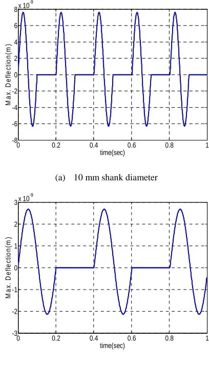
The finite element model used to determine deformations of the tool/holder deflection when a point force is applied at its end. Many simulations could be performed for periodic end mills with different cutting tool material, variable shank diameter, overall length and number of flutes. Modeling and FE analysis can be unpractical and time consuming for each tool configuration in a virtual machining environment. Therefore, simplified equations are created to predict the holder deflection for given geometric parameters and density. The analytical data for Matlab model by using 4 flutes, 10 mm shank diameter and 170 mm length. Examples of the periodic and straight deflection elements are shown in figures 4 and 5. It is possible to determine the maximum deflection for cutting tool holders with
four periodic and straight cells of the tool holders that have shank diameters of 10 and 20 mm [13], as shown in figures 6 and 7:
N
D
L
E
CF
Defl
=
34max
(11)
F is the resultant applied force and E is the modulus of elasticity of the tool material. For 4 cutting tool flutes, the constant C is 9.05 and N is 0.950 and the holder stiffness is 75 N/mm. The largest singular value of the deflection computed from the model rapprochement 4.9*10-5 m.
0 0.2 0.4 0.6 0.8 1
-8 -6 -4 -2 0 2 4 6 8x 10
-9
M
a
x
.
D
e
fl
e
c
ti
o
n
(m
)
time(sec)
(a) 10 mm shank diameter
0 0.2 0.4 0.6 0.8 1
-3 -2 -1 0 1 2 3x 10
-9
M
a
x
.
D
e
fl
e
c
ti
o
n
(m
)
time(sec)
(b) 20 mm shank diameter
111306-3838 IJMME-IJENS © December 2011 IJENS I J E N S
0 0.2 0.4 0.6 0.8 1
-4 -3 -2 -1 0 1 2 3 4x 10
-9
M
a
x
.
D
e
fl
e
c
ti
o
n
(m
)
time(sec)
(a) 10 mm shank diameter
0 0.2 0.4 0.6 0.8 1
-2 -1.5 -1 -0.5 0 0.5 1 1.5
2x 10
-9
M
a
x
.
D
e
fl
e
c
ti
o
n
(m
)
time(sec)
(b) 20 mm shank diameter
FIGURE 7 - Maximum deflection for a tool holder with 4 periodic cells
V. ANALYTICAL MODELLING
FE method is used to determine deformations of the tool holder deflection when a point force is applied at its end. Many simulations could be performed for periodic end mills with different cutting tool material, variable shank diameter and overall length and. Modeling and FE analysis can be unpractical and time consuming for each tool configuration in a virtual machining environment. Therefore, simplified equations are created to predict the holder deflection for given geometric parameters and density. The analytical data for Matlab model by using 4 flutes, 10 mm shank diameter and 170 mm length. The analytical equations for computing degree of
freedoms per node and the whole system are pasted from Matlab model as:
nel=8; % no of elements
ndof=3; % DOF's/node
nnel=2; % nodes/element
nnode=(nnel-1)*nel+1;% nodes/system
sdof=nnode*ndof; % DOF's/system
edof=nnel*ndof; % DOF/element
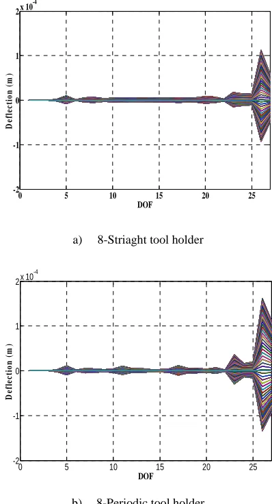
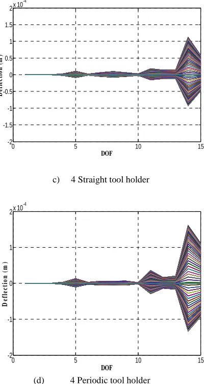
For a holder consists of 8 elements, the number degree of freedom (DOF) becomes 27, and for 4 elements, DOF equals 15. Examples of straight and periodic tool/holder deflection for 10 mm shank diameter are shown in the following figures, 8 and 9.
0 5 10 15 20 25
-2 -1 0 1
2x 10
-4
DOF
D
ef
le
ct
io
n
(
m
)
a) 8-Striaght tool holder
0 5 10 15 20 25
-2 -1 0 1 2x 10
-4
DOF
D
ef
le
ct
io
n
(
m
)
b) 8-Periodic tool holder
111306-3838 IJMME-IJENS © December 2011 IJENS I J E N S
0 5 10 15
-2 -1.5 -1 -0.5 0 0.5 1 1.5
2x 10
-4
DOF
D
ef
le
ct
io
n
(
m
)
c) 4 Straight tool holder
0 5 10 15
-2 -1 0 1 2x 10
-4
DOF
D
ef
le
ct
io
n
(
m
)
(d) 4 Periodic tool holder
FIGURE 9 - Deflection of straight and periodic tool holders modeled by 4 finite elements
VI. FREQUENCY RESPONSE ANALYSIS
The previous analysis of the holder deflection is mainly based upon the time domain approach. The eigenvalues and eigenvectors directly produce solutions in time domain in the form of time response functions. Sometimes, the time domain analysis is not the best choice, especially for cutting forces and deflection analysis. One supplementary approach is the frequency domain analysis, which has major advantages over the time domain [24]. The Fast Fourier Transform (FFT) and evaluation of the frequency response function for multiple Degree of
Freedom (DOF) system are presented as shown in figures 10 and 11.
VII. CONCLUSION
This paper has presented a new class of periodic machine tool holder system for isolating the deflection of cutting tool holder to the machine tool table in an attempt to produce a quiet surface finish. The model is developed to describe the dynamics of wave propagation in a periodic tool holder. The model is derived using the theory of finite element method (FEM). The model applied for four and eight elements; and the transfer matrix formulation for each element is given.
For accounting the size effect, this paper proposes a simplified and efficient method for the prediction of the tool holder deflection in conjunction with the resultant cutting forces for cylindrical end milling that are valid for a wide range of cutting conditions. The instantaneous deflection with different periodic elements is executed from Matlab model which has been prepared for this work. The program depends on factors in the implementation of fixed and variable. The cutting parameters such axial depth of cut (Ad), radial depth of cut (Rd), feed per tooth (f), and spindle rotation speed (n) are kept predetermined for all run outs. Cutting tool shank diameter and number of periodic elements, choose the form of the cutting holder, if it is straight or periodic and should be selected in order to satisfy tooth engagement condition. In addition, an attempt to produce
attenuation curves to describe the dynamic
characteristics of periodic and straight elements in time and frequency domains for forces and deflection.
111306-3838 IJMME-IJENS © December 2011 IJENS I J E N S
respectively. Also, the maximum deflection values could be predicted from figures 6 and 7 as 7.5x10⁻⁹ and 2.8x10⁻⁹ for straight holder, and 3.15x10⁻⁹ and 1.1x10⁻⁹ for periodic tool holder using the same diameters.
Higher accuracy of FFT models arises, from the fact that at higher frequency magnitude, the shorter the deflection of the holder. Therefore, accurately capture the dynamic deflection of the structure, smaller mesh is required, which means larger model and more computational effort. On the other hand, the nature of the dynamic stiffness matrix is that the dynamic solution embedded in the matrix model of the element, thus less elements are required to present the structure with higher accuracy.
VIII. FUTURE WORK
Many mechanical systems require modeling
before their vibrations can be analyzed. The
basic formulations for vibration suppression of
the periodic mechanical system could be
presented, based on the theory of dynamic
vibration. The problem of cutting tool vibration
is faced frequently in a variety of engineering
products. To present a solution for this goal, new
present technique could be presented after
appropriate assumptions are made, including the
number of degrees of freedom (DoF) necessary.
Appropriate mathematical methods will be
applied to the different equations. The governing
equation motion for the elements is based on the
Euler–Bernoulli beam theory, with six nodal
variables for the elements, four for bending and
two for the axial forces. Potential and kinetic
energies associated with approximation given by
the model will be considered.
0 200 400 600 800 1000 1200
0 0.5 1 1.5 2 2.5x 10
-7
F
F
T
Frequency(Hz)
(a) FFT for 4 straight elements and 10 mm shank diameter
0 200 400 600 800 1000 1200
0 0.5 1
1.5x 10
-7
F
F
T
Frequency(Hz)
(b) FFT for 4 periodic elements and 10 mm shank diameter
-3000 -200 -100 0 100 200 300
0.2 0.4 0.6 0.8
1x 10 -5
Frequency (Hz)
F
F
T
111306-3838 IJMME-IJENS © December 2011 IJENS I J E N S
-3000 -200 -100 0 100 200 300
0.2 0.4 0.6 0.8
1x 10
-5
Frequency (Hz)
F
F
T
(d) FFT for 4 periodic elements and 20 mm shank diameter
FIGURE 10 – FFT for 4 straight and periodic elements, 10 and 20 mm shank diameters.
-6000 -400 -200 0 200 400 600
0.5 1 1.5 2 2.5
3x 10
-7
Frequency (Hz)
F
F
T
(a) FFT for 8 straight elements and 10 mm shank diameter
-6000 -400 -200 0 200 400 600
0.5 1 1.5 2 2.5 3 3.5
4x 10
-7
Frequency (Hz)
F
F
T
(b) FFT for 8 periodic elements and 10 mm shank diameter
-3000 -200 -100 0 100 200 300
0.2 0.4 0.6 0.8
1x 10 -5
Frequency (Hz)
F
F
T
(c) FFT for 8 straight elements and 20 mm shank diameter
-3000 -200 -100 0 100 200 300
0.2 0.4 0.6 0.8 1 1.2x 10
-5
Frequency (Hz)
F
F
T
(d) FFT for 8 periodic elements and 20 mm shank diameter
FIGURE 11 – FFT for 8 straight and periodic elements, 10 and 20 mm shank diameter
Nomenclature
A cross-sectional area, m2
C cutting force coefficient
E young's modulus, N/m2
EI flexural rigidity of the holder
F total force magnitude
f table feed rate, mm/min
h instantaneous chipthickness, m
I area moment of inertia, m4
K stiffness matrix
Ke element stiffness matrix
l element length thickness, m
M overall mass matrix
Me element mass matrix
n spindle speed, rev/s
t time, s
111306-3838 IJMME-IJENS © December 2011 IJENS I J E N S w transverse displacement of the tool holder, m
β end mill helix angle θ cutting force angle ρ material mass density, kg/m3
γ torsional constant
REFRENCES
[1] S. Smith, J. Tlusty, “An overview of modeling and simulation of the milling process”,
Transactions of the ASME: Journal of
Engineering for Industry 113 (May) (1991) 169– 175.
[2] A.E. Bayoumi, G. Yucesan, L.A. Kendall, “An analytic mechanistic cutting force model for milling operations: a theory and methodology”,
Transactions of the ASME: Journal of
Engineering for Industry 116 (August) (1994) 324–339.
[3] E. Budak, Y. Altintas, E.J.A. Armarego, “Prediction of milling force coefficients from orthogonal cutting data”, Transactions of the ASME: Journal of Manufacturing Science and Engineering 118 (May) (1996) 216–224.
[4] M.A. Elbestawi, F. Ismail, R. Du, B.C. Ullagaddi, “Modeling machining dynamics
including damping in the tool-workpiece
interface”, Transactions of the ASME: Journal of Engineering for Industry 116 (November) (1994) 435–439.
[5] F. Ismail, M.A. Elbestawi, R. Du, K. Urbasik, “Generation of milled surface including tool dynamics and wear”, Transactions of the ASME: Journal of Engineering for Industry 115 (August) (1993) 245–252.
[6] F.M. Kolarits, W.R. DeVries, “A mechanistic dynamic model of end milling for process controller simulation”, Transactions of the ASME: Journal of Engineering for Industry 113 (May) (1991) 176–183.
[7] D. Montgomery, Y. Altintas, “Mechanism of cutting force and surface generation in dynamic milling”, Transactions of the ASME: Journal of Engineering for Industry 113 (May) (1991) 160– 168.
[8] T.C. Ramaraj, E. Eleftheriou, “Analysis of the mechanics of machining with tapered end milling cutters”, Transactions of the ASME: Journal of Engineering for Industry 116 (August) (1994) 398–404.
[9] J.W. Sutherland, R.E. Devor, “An improved method for cutting force and surface error prediction in flexible end milling systems”,
Transactions of the ASME: Journal of
Engineering for Industry 108 (November) (1986) 269–279.
[10]T.S. Babin, J.M. Lee, J.W. Sutherland, S.G. Kapoor, “A model for end milled surface topography”, Proceedings of the 13th North American Metalworking Research Conference, 1985, pp. 362-368.
[11]M.C. Shaw, Metal Cutting Principles, Clarendon Press, Oxford, 1984.
[12]J. Tlusty, P. Macneil, Dynamics of cutting forces in end milling, Annual of CIRP 24 (1975) 21–25.
[13]J. Tlusty, Machine dynamics, in: R.I. King (Ed.), Handbook of high-speed machining technology, Chapman and Hall, New York, 1985.
[14]Min Wan, a, Wei-Hong Zhanga, Jian-Wei Danga and Yun Yanga, “A novel cutting force modeling method for cylindrical end mill”, Applied Mathematical Modeling Volume 34, Issue 3, March 2010, Pages 823-836.
[15]Min Wan*, Wei-Hong Zhang, Jian-Wei Dang, Yun Yang, “A novel cutting force modeling method for cylindrical end mill”, Applied Mathematical Modeling, 34, 823–836, 2010.
[16]Mead, D.J., “Wave Propagation in Continuous Periodic Structures: Research Contributions from Southampton, 1964-1995”, Journal of Sound and Vibration, Vol. 190, No. 3, 1996, pp. 495-524.
[17]Ungar, E.E., “Steady-State Response of One-Dimensional Periodic Flexural Systems,” The Journal of the Acoustic Society of America, Vol. 39, No. 5, 1966, pp. 887-894.
111306-3838 IJMME-IJENS © December 2011 IJENS I J E N S
and Plates,” Journal of Sound and Vibration, Vol. 13, No. 1, 1970, pp. 89-101
[19]Faulkner, M.G. and Hong, D.P., “Free Vibration of Mono-Coupled Periodic System,” Journal of Sound and Vibration, Vol. 99, No. 1, 1985, pp. 29-42.
[20]Mead, D. J. and Yaman, Y., “The Response of Infinite Periodic Beams to Point Harmonic Forces: A Flexural Wave Analysis,” Journal of Sound and Vibration, Vol. 144, No. 3, 1991, pp. 507-530
[21]Mead, D. J., White, R. G., and Zhang, X. M., “Power Transmission in a Periodically Supported Infinite Beam Excited at A Single Point,” Journal of Sound and Vibration, Vol. 169, No. 4, 1994, pp. 558-561.
[22]Langley, R. S., “A Transfer Matrix Analysis of the Energetic of Structural Wave Motion and
Harmonic Vibration,” Proceedings:
Mathematical, Physical and Engineering
Sciences, Vol. 452, No. 1950, 1996, and p. 1631-1648.
[23]Leung, A. Y. T., and Zeng, S. P., “Analytical Formulation of Dynamic Stiffness, “Journal of Sound and Vibration, Vol. 177, No. 4, 1994, pp. 555-564.
[24]Doyle, J. F., Wave Propagation in Structures: Spectral Analysis Using Fast Discrete Fourier Transforms, Mechanical Engineering Series, 2nd ed., Springer-Verlag, 1997.
[25]E. Kivanc, E. Budak, “Development of analytical end mill deflection and dynamic models”, Proceedings of ASME IMECE Conference, IMECE 2003-42301, Washington, DC, USA, November, 2003.
[26]H. Akesson, T. Smirnova, L. Hakansson, I. Claesson and T. Lago, “Investigation of the Dynamic Properties of a Milling Structure, Using
Tool holder with moderate overhang”,