on Energy Web and Information Technologies
Research Article
Machine-Converter Voltage Source for Autonomous
Systems of Distributed Power Supply
A.V. Glazachev
1,*, K.V. Obraztsov
1, A.D. Umurzakova
1, V. I. Susdorf
2, S. Halasz
31Tomsk Polytechnic University, School of Energy & Power Engineering, av. Lenina, 30, 634050, Tomsk, Russian Federation
2
Komsomolsk-na-Amure State Technical University, Electric Drive and Automation of Industrial Installations, av. Lenina, 27, 681013, Komsomolsk-na-Amure, Russian Federation
3Budapest University of Technology and Economics, Department of Electric Power Engineering, Jozef ut., 18, H-1111,
Budapest, Hungary
Abstract
The paper presents electric Machine-Converter Voltage Source (MCVS) for systems of distributed power supply with shaping output voltage in an electric machine (generator). The MCVS consists of electric machine and a cycloconverter that has three-phase bridge circuit. Both synchronous generator and asynchronous exciter, which are located in one housing, operate as electric modulation generator. Functional diagram of complex MCVS, where the output voltage is stabilized by simultaneous or separate use of several control channels. We analyzed output voltages of MCVS and dependences of non-sinusoidality and distortion factors on ratio rotational speed of generator to output voltage frequency of MCVS for various amplitude modulation indexes and control modes of cycloconverter.
Keywords: Machine-converter voltage source, autonomous distributed power supply system, output voltage envelope, cycloconverter, harmonic analysis, distortion factor, control optimization.
Received on 23 April 2018, accepted on 26 June 2018, published on 10 July 2018
Copyright © 2018 A. V. Glazachev et al., licensed to EAI. This is an open access article distributed under the terms of the Creative Commons Attribution licence (http://creativecommons.org/licenses/by/3.0/), which permits unlimited use, distribution and reproduction in any medium so long as the original work is properly cited.
doi: 10.4108/eai.10-7-2018.154980
1. Introduction
One of the main goals of designing Machine-Converter Voltage Sources (MCVS) for autonomous power supply systems is outputting electric power, which parameters meet the quality standards [1–7, 11]. Main quality factors of independent power supply sources are rated magnitude and frequency of output voltage. Deviations of the load, supply voltage and currents are reasons of failures of expensive equipment. Therefore, research and development circuits of Machine-Converter Voltage Sources (MCVS) as main component of autonomous distributed power supply systems that can stabilize output parameters is a problem of current importance.
2. Autonomous sources with shaping output
voltage waveform and stabilization of electric
output parameters in electric machine
We analyzed existing stabilization methods [10–12, 14] of output electric parameters (output voltage magnitude and frequency) of systems «electric generator – static frequency converter». The analysis shows that to generate sine wave of output voltage by means of electric generator (EG) the most viable method for wide-range variation of the generator speed and the power consumed is voltage regulation in the generator excitation windings [9]. Besides, the three-phase voltage system of stable frequency can be generated in an autonomous source with electromagnetic shaping of the output voltage waveform, which consists of two electric AC machines that are mount on the same shaft by recovering modulating functions by means of static converter.
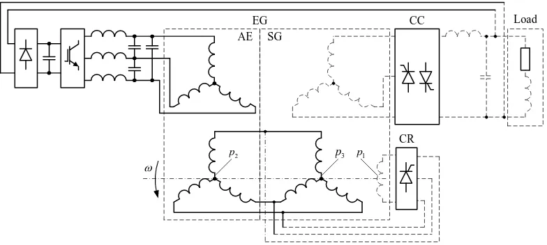
Figure 1 shows functional diagram of autonomous single-phase voltage source of stable frequency.
w AE SG CC CR EG 1 p 2
p p3
Load
Figure.1. Functional diagram of autonomous single-phase voltage source of stable frequency with shaping the
output voltage waveform of electric generator
Here modulation type electric generator (EG) consists of synchronous generator (SG) and asynchronous exciter (AE), which are mounted on the same shaft and located in one housing [8, 12]. Windings of the electric machines of EG are made with different number of pole pairs, which allows providing independence of output voltage frequency on rotation speed of SG shaft. Excitation winding of SG is connected to the rotor winding of AE via controlled rectifier (CR). Stator winding of AE is connected to autonomous voltage inverter, and the armature winding of SG – to cycloconverter (CC). An additional three-phase winding, which is connected to rotor winding of AE, is wound on rotor of SG. Output armature winding of SG is carried out as three single-phase winding, which are shifted in space for
angle 2 3
el. degrees. EG outputs power to the load via
three-to-one-phase cycloconverter (CC).
Operation of MCVS with shaping the output voltage waveform in electric machine can be explained using figure 1. If the rotor is rotated and the winding of AE is supplied by PWM autonomous inverter, an EMF is induced in rotor winding of AE with frequency given by:
2 1p1 0
w w w , (1) where w1 is angular frequency of rotational EMF of generator; p1 is pole pair number of windings of SG;w0 is angular frequency of stator winding current of AE.
Excitation winding of SG is a load for asynchronous exciter via controlled rectifier. In armature winding of synchronous generator an EMF is induced by DC excitation winding given by:
1 1 1 1
1 1 1 1
1 1 1 1
sin 2 sin 3 2 sin 3 m m m
e t E p t
e t E p t
e t E p t
w w w
. (2)
Angular frequency of the induced EMF is given by:
4 1p1
w w .
Additionally wound three-phase winding of SG is also the load for AE. Phase-to-neutral EMFs of armature windings of SG that are caused by the field of additional three-phase winding of SG are functions of angular frequency w4 in terms of formulae:
2 2 1 2 3 0
2 2 1 2 3 0
2 2 1 2 3 0
sin 2 sin 3 2 sin 3 m m m
e t E p p t
e t E p p t
e t E p p t
w w w ,
4 4 1 p2 p3 0
w w
w
w
. (3)where p2 is pole pair number of windings of AE; p3 is pole pair number of additional three-phase excitation winding of SG.
Adding together the two EMFs in armature winding of SG the resulting EMF is generated, which magnitude is oscillating with beat frequency given by:
1 1 2 3 0 0
1 1 2 3 0 0
1 1 2 3 0 0
2 sin cos
2 2
2
2 sin cos
2 3 2
2
2 sin cos
2 3 2
A m
B
С
p p p
e t E t t
p p p
e t E t t
p p p
e t E t t
w w w
w w
w w
4 4 1 p1 p2 p3 0
As result of extraction of the output voltage envelope by means of cycloconverter CC, we got independence of beat frequency w4 on the generator shaft speed, i.e.
4 0
w w . (5)
But here it is necessary to choose number of pole pairs of windings of synchronous generator, asynchronous exciter
and additional three-phase excitation winding of SG in terms of formula:
1 2 3
p p p . (6)
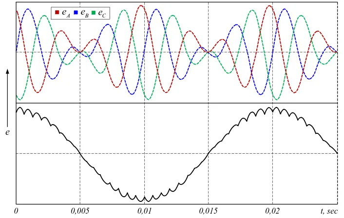
In figure 2 and 3 you can see graphic illustration of shaping the EMF waveforms of armature windings of SG and output voltage envelope of autonomous MCVS.
0 0,005 0,01 0,015 0,02 t, sec
e
B
e
C
e
A
e e1A e2A
1B
e e2B
1C
e e2C
Figure. 2. Waveforms of induced EMFs and resulting EMFs of phases of armature winding of SG
0 0,005 0,01 0,015 0,02 t, sec
e
A
e eB eC
3.
Combination
circuit
of
Machine-Converter
Voltage
Source
with
stabilization of output parameters
Stabilization of output voltage of MCVS with shaping output voltage waveform in electric generator can be realized via several channels: by means of DC excitation winding circuit; by means of AC excitation winding circuit; by means of cycloconverter circuit. Furthermore, one is able to use simultaneously two or all of the channels enabling fine varying amplitude modulation percentage and stabilizing output electrical parameters.
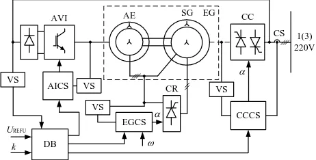
In figure 4 a functional diagram of MCVS circuit is shown, in which the output voltage can be stabilized by means of several control channels.
DB
EGCS VS VS AICS VS
VS
CCCS
AVI AE SG EG
CR
w a
CC
CS
a
1(3) 220V
k UREFU
Figure 4. Functional diagram of MCVS of stabilizing
system of the electrical output voltage parameters of combination type
In MCVS circuit, which uses stabilization of the output voltage by means of DC excitation winding circuit [2, 10, 12], control system (CS) of autonomous voltage inverter (AVI) with PWM (see figure 4), has constant reference signal of frequency and magnitude of excitation current of AE, which does not depend on output voltage and frequency of MCS. Input signals of the Electrical Generator Control System (EGCS) are: speed of driving shaft ω and reference value of voltage UREFU, which is compared with current value of output voltage amplitude (in Difference Block (DB)). Regulation of magnitude of output voltage of MCVS is carried out by changing angle α of Controlled Rectifier (CR), which feeds the circuit of DC excitation winding of generator EG.
In MCVS circuit, which realizes stabilization of the output voltage by means of AC excitation winding circuit [2, 10, 12] the output voltage is regulated by means of autonomous voltage inverter AVI, which feeds the stator circuit of AE. In addition, in DC excitation winding circuit of SG can be applied Controlled Rectifier (CR), instead of the uncontrolled one. However, it leads to certain limitations for practical use of such MCVS, since with no ability to correct the biasing current of SG the effective range of the output voltage stabilization will be reduced, when the angular speed of SG is changed [13, 14]. CC has its own control system with firing angles (α) and demodulates
output voltage of SG. The firing angle of cycloconverter CC is generated subject to signals from current sensor (CS) and voltage sensor (VS) [9, 12, 14].
Joint use of these stabilization methods in circuit of MCVS, shown in fig. 4, allows increasing control accuracy and expanding speed range of driving shaft even for one-channel excitation system of generator EG.
In such a way the three-phase voltage system of stable frequency can be achieved in MCVS with shaping the output voltage waveform, which is made of two electric AC machines that are mount on the same shaft, and then by extracting modulating function by means of cycloconverter CC. This enables to get an output voltage of MCVS the one-phase voltage, which is close in waveform to sine wave, with frequency that is equal to half of AC excitation current frequency of AE and does not depend on the rotational speed of EG [10, 15].
Main advantage of MCVS with shaping the output voltage waveform in electric machine is overlapping electric machines with different number of pole pairs on one magnetic core, which allow providing no sliding contacts and increasing reliability of the system. Introduction of additional components that operate in feedback circuit carry out excitation of generator, stabilization of magnitude and frequency of the output voltage via two channels: control of excitation and of the converter circuit. Ability to control the amplitude modulation percentage in wide range allows achieving good power factors of MCVS with high quality of the output voltage waveform.
After researching MCVS [8, 9, 11, 12, 15] we have found out that the waveform of the output voltage envelope depends on amplitude modulation percentage index and decreasing the index causes «delaying» of the envelope in regions with small voltages, which leads to deviation of the output voltage waveform from sine waveform. One can solve this problem most effective due to optimization of the control mode of CC [10, 12, 17].
Introduction of additional components into feedback of CC and using closed loop control system by introducing the voltage feedback allows improving quality of output voltage [10, 15-17].
4. Harmonic analysis of the load voltage of
autonomous Machine-Converter Voltage
Source with stable frequency
For comparative analysis of studied load voltages of MCVS for various control modes of CC we have to determine non-sinusoidality factor kn, distortion factor kU and their dependence on ratio of rotational speed of
generator to output voltage frequency rot out
w
w for various
amplitude modulation indexes k.
These factors are determined in terms of formulae:
1
n H
U k
U
, H1
U H
U k
U
where UH is effective value of output voltage; UH1 is effective value of fundamental harmonic of output voltage; U is total effective value of higher harmonics of output
voltage.
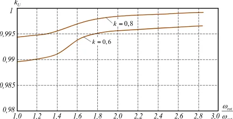
In diagrams (figures 5–8) you can see functional dependences of the factors on ratio of rotational speed of generator to output voltage frequency of MCVS for various amplitude modulation indexes.
1,0 1,2 1,4 1,6 1,8 2,0 2,2 2,4 2,6 2,8 0
5 10 15
, %
n
k
rot
out
w w
0, 6
k
0,8
k
3,0 20
Figure 5. Functional dependence of non-sinusoidality
factor of output voltage on ratio of rotational speed of generator to output voltage frequency of MCVS with
open control system of CC
1,0 1,2 1,4 1,6 1,8 2,0 2,2 2,4 2,6 2,8 0
5 10 15
, %
n
k
rot
out
w w
0, 6
k
0,8
k
3,0 20
Figure 6. Functional dependence of non-sinusoidality
factor of output voltage on ratio of rotational speed of generator to output voltage frequency of MCVS with
closed control system of CC
1,0 1,2 1,4 1,6 1,8 2,0 2,2 2,4 2,6 2,8 3,0 0,98
0,985 0,99 0,995 1
rot out
w w 0, 6
k
0,8
k U
k
Figure 7. Functional dependence of distortion factor of
output voltage on ratio of rotational speed of generator to output voltage frequency of MCVS with open control
system of CC
1,0 1,2 1,4 1,6 1,8 2,0 2,2 2,4 2,6 2,8 3,0 0,98
0,985 0,99 0,995 1
rot out
w w 0, 6
k
0,8
k U
k
Figure 8. Functional dependence of distortion factor of
output voltage on ratio of rotational speed of generator to output voltage frequency of MCVS with closed
control system of CC
From graphs shown in figures 5–8 you can see that harmonic structure of MCVS voltage, when changing load, is distinctly better due to optimization of the control mode of CC in the range up to double ratio of rotational speed of generator to output voltage frequency. Particularly at the double ratio the non-sinusoidality factor does not exceed standard value (5%) for
k
0,8
.Conclusions
Autonomous sources with shaping the output voltage waveform at output of EG by adding EMFs of close frequencies are prospective and provide high quality of output voltage waveform in autonomous systems of distributed power supply.
We found that the machine-converter source described in the paper provides output voltage control in required range, as well as it maintains the frequency and magnitude of output voltage in accordance with requirements to autonomous power supply systems.
We discovered that due to optimization of the control mode of CC the quality of output voltage could be improved. Particularly at the double ratio the non-sinusoidality factor does not exceed standard value (5%) for
k
0,8
.Acknowledgments
The research is carried out at Tomsk Polytechnic University within the framework of Tomsk Polytechnic University Competitiveness Enhancement Program.
References
[1].Guzhulev E.P. Alternative renewable energy sources / E.P. Guzhulev, V.N. Goryunov etc. – 2004, Omsk: Publ. house of Omsk State Technical University (in Russian).
sources in the Russian Far East. Far-Eastern power consumer. № 4–5 April-May 2005, pp. 32–33 (in Russian).
[3]. Sharaf A.M, Wang W. A Low-Cost Voltage
Stabilization and Power Quality Enhancement Scheme for a Small Renewable Wind Energy Scheme, Proceedings of the IEEE-ISIE 2006 Conference, Montreal, Quebec, Canada July 2006. DOI: 10.1109/ISIE.2006.295871
[4]. Sharaf А.М., Altas I.H., Ozkop E. Voltage and energy utilization enhancement in a Stand-alone WECS Using a fuzzy logic controlled SPWM converter interface scheme // Power System Conference 2008. MEPCON 2008. 12th International Middle-East, pp. 330-334. DOI: 10.1109/MEPCON.2008.4562313
[5]. Jain M.K, Dahiya R. Enhancement of voltage profile of wind connected system by power filter compensation scheme // Power Communication and Information Technology Conference (PCITC) 2015 IEEE, pp. 947-952. DOI:10.1109/PCITC.2015.7438133
[6].Kharitonov S.A. Voltage stabilization in electrical supply system with magnetoelectric generator / S.A. Kharitonov, D.V. Makarov, A.S. Kharitonov // Power supply. – 2017. – № 1. – p. 16–37. (in Russian).
[7]. A new approach to voltage regulation in self-sustained power supply systems in mines / S.A. Kharitonov, E.Ya. Bukina, D.V. Makarov, A.S. Kharitonov // Physicotechnical problems of minerals development. – 2017. – № 2. – p. 59–68. (in Russian).
[8].Petukhov A.M. Mathematical model of combined electric generator/ A.M. Petukhov, V.M. Kuzmin, R.V. Kuzmin, I.N. Dubrovskiy //Electrotechnica. – 2013. – №5. pp. 45–49. (in Russian).
[9].Bortsova T.Yu., Lukutin B.V. Stabilization of equivalent load of microhydroelectric power plant //Proceedings of ninth All-Russian scientific conference «Power engineering: ecology, reliability, safety» – vol. Т1. – Tomsk, 3-5 of December, 2003 г. – Tomsk: Publ/ House of Tomsk Polytechnic University, 2003. – pp. 105–108. (in Russian).
[10]. Dementyev Yu.N., Glazachev A.V., Negodin K.N., Vajda I., Susdorf V.I. Stabilization of Electrical Parameters of Machine-Converter Voltage Source. EAI Endorsed Transactions on Energy Web and Information Technologies. – 2018 Vol. 5, iss. 16. – [e1, 9 p.] DOI: 10.4108/eai.30-1-2018.153813
[11]. Kuzmin V.M., Susdorf V.I. Mathematical model of autonomous source with shaping of output voltage waveform // Notes of Komsomolsk-na-Amure State Technical University. 2011. Vol. 1. № 5. pp. 23–28. (in Russian).
[12]. Kinitsa O. I. Autonomous voltage source of stable frequency for distributed power supply systems: PhD Thesis: 05.09.03. – Komsomolsk-na-Amure, 2006. – 132 p.: (in Russian).
[13]. Bedri Kekezoglu, Mugdeşem Tanriöven, Ali Erduman. A New Wind Turbine Concept: Design and Implementation. Acta Polytechnica Hungarica Vol. 12, No. 3, 2015 DOI: 10.12700/APH.12.3.2015.3.12
[14]. Petukhov A.M. Determining magnitude and
frequency of EMFs in output windings of combined electric
generator from often excitation and rotation of rotor /A.M. Petukhov, V.M. Kuzmin// Proceedings of V International Scientific conference «Electrotechnics and energy-efficient technologies». – Lipetsk: «Lipetsk State Technical University», 2012. – pp. 70 – 75. (in Russian).
[15]. Yury Dementyev, Roman Kuzmin, Aleksandr
Serikov, Viktor Suzdorf, Kirill Negodin, Istvan Vajda. Gearless Micro Hydropower Plant for Small Water-Course. Acta Polytechnica Hungarica Vol. 14, No. 4, 2017 DOI: 10.12700/APH.14.4.2017.4.9
[16]. Bevz D.V., Payuk L.A., Voronina N.A. The Controlled Electric Drive of the Automatic Cooling System of the Engine Room on a Vessel // MATEC Web of Conferences. – 2017. – Vol. 91: Smart Grids 2017. – [01037, 5 p.]. DOI: 10.1051/matecconf/20179101037
[17]. Abderrahmen Mechter, Karim Kemih, Malek