Power
Mojtaba Saeedimoghadam
*and Majid Dehghani
Department of Electrical Engineering, Najafabad Branch, Islamic Azad University, Isfahan, Iran
Corresponding author: Mojtaba Saeedimoghadam
ABSTRACT: Static switch is placed between micro-grid and national power grid, and performs
connection and disconnection of micro-grid to power grid. One important duty of static switch is to detect recursion of power (power reverse) from micro-grid to power grid. Reverse power refers to both active and reactive powers. In present paper, different cases of power recursion from micro grid to power grid are studied and simulated, and an appropriate accurate detection system is designed and simulated. Simulation results, verify the accuracy and authenticity of this system.
Keywords: Micro-Grid, Static Switch, Reverse Power.
INTRODUCTION
Nowadays, power quality, safety and reliability have significant importance in power network, such that a vast area of researches is allocated to these characteristics. Utilizing novel control method beside distributed generation sources by considering levels of safety, quality and reliability, creates a new concept called micro-grid. Micro-grid meets current needs of users and can deliver power to sensitive loads with high qualities (Rocabert et al., 2011; Casey et al., 2012; Eloy-Garcia et al., 2013). Each micro grid is able to operate in two islanded and power grid connected modes. In especial circumstances, micro-grid is separated of grid and gets into islanding mode, and will be re-connected to power grid via static switch (Mao et al., 2012).
Decision making in static switch control system is based on micro-grid policymaking. This policymaking is defined such that when micro-grid is faced with power shortage, then it will always be connected to power grid via static switch, and whenever it is able to supply the loads, it is isolated of power grid. This performance of static switch, is called reverse power recognition. One of the most important duties of static switch is to identify power reverse. In present paper, different cases of power reverse from micro-grid to power grid is investigated and by studying and simulating these different cases, an appropriate accurate reverse power recognition system in static switch is designed (Perkins et al., 1999; Liu et al., 2012; Katiraei et al., 2005; Zeineldin et al., 2006).
Static switch
Micro-grid is able to operate in two islanded and power grid connected modes. Static switch is located between micro-grid and power grid, which operation of ON/OFF from grid is done via this switch. Static switch has three duties in grid: 1- To synchronize grid with power grid 2- Identifying short circuit and separating micro-grid from power micro-grid 3- To detect power reverse from micro-micro-grid to power micro-grid (Ustun et al., 2012).
727 Figure 1. Position of a static switch in micro-grid
Micro-grid policymaking is based on the point that when power sources in micro-grid cannot supply their own loads, then static switch connects the micro-grid tower grid, so power shortage is compensated by power grid. When micro-grid sources are able to provide required power of micro-grid loads, then power flow from micro-grid to power grid is changed and so, static switch separates the micro-grid from power grid. Identifying power reverse from micro-grid to power grid, is one main important duty of static switch.
Computing the power
In a power system, apparent power in time domain, is obtained via relation (1):
In fact, apparent power value is attained through multiplying voltage by current. If relation (1) is used to compute apparent power, then its real and imaginary parts equal to active and reactive powers respectively, as relation (2):
Q j P I V
S (2)
Static switch must separate micro grid from power grid in two active and reactive power reverse. Power reverse in time domain is implemented in Mat lab as diagram block:
Figure 2. Diagram block of power computation in time domain
Powers obtained by diagram block (figure 2) are in form of sine waves and using such signals, makes it
complicated to make decisions. Hence, dq coordinate system is utilized in power systems simulation. This
coordinate system, interprets equations of 3-phase system on axes q and d. In dq coordinate system, equations
are simpler and calculations are easily accomplished. After that if necessary, answers might be transferred into time domain.
If voltage and current in time domain are transferred into dq coordinate system, then active and reactive
powers are computed by relations (3) and (4) (Ma et al., 2012):
q q d d I V I
V
P (3)
q d d
q I V I
V
P (4)
Decision making according to power value in dq coordinate system, due to its linearity is so simple. Power is linear,
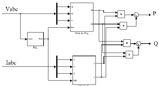
since dq coordinate system is rotating. Power computation diagram block in dq coordinate system is implemented
as figure 3 which relations (3) and (4) are exactly implemented.
V
I
728
Figure 3. Power computation diagram block in dq coordinate system
Power computations in dq coordinate system are implemented in Matlab as figure 3. Voltage phase angles must be
calculated to transfer time domain parameters into dq coordinate system. As it is shown in figure (3), voltages
phase angle is identified by phase-locked loop (PLL).
Reverse power relays
If current direction is determined, then it is possible to determine power flow direction as well. In this system, power flow direction is same as current's, since here it might be said that system voltage is independent of power flow. Operation of reverse power relays is based on current flow direction and by detecting current direction, power flow direction is determined as well.
In reverse power relays, sampling is performed for micro-grid 3-phase current. 3-phase current is transferred to Fortescue system by Fortescue transfer which includes three positive, negative and zero components. Considering location of sampler device, if power flow direction is from power grid to micro-grid, then domain of current's positive component has a magnitude, and if power flow direction is from micro-grid to power grid, then domain of current's positive component equals to zero. Hence, it is possible to determine current direction i.e. power flow direction here, by obtaining Fortes cue transfer (Ye et al., 2012; Bellini et al., 2012).
Due to economic issues, it is not recommended to uses these relays. These relays are too sensitive to partial instantaneous power reverse as well and in case of occurring some vibrations may some part of power returns to power grid and relay fails in decision making (Illindala et al., 2007).
If dq coordinate system is used to compute the power, then it is possible to calculate power at any moment and
also as average.
Simulation
Figure 1, is simulated as a power grid connected micro-grid sample which illustrates a simple modeling of micro-grid.
Power return determination system in time domain is designed and simulated based on third section descriptions and diagram block of figure 3. Figures 4 and 5 represent 3-phase voltage and current of static switch in normal performance respectively. Considering current in figure 5, static switch is in closed mode which indicates power flow from power grid to micro-grid.
Figure 4. 3-phase voltage of static switch in normal performance mode 9.9 9.91 9.92 9.93 9.94 9.95 9.96 9.97 9.98 9.99 10
-400 -300 -200 -100 0 100 200 300 400
Time (s)
3
P
ha
se
V
ol
ta
ge
(
v)
729 Figure 5. 3-phase current of static switch in normal performance mode
Apparent power is obtained via multiplying voltage by current. Real value of apparent power equals to active power and imaginary value of apparent power is equal to reactive power. Diagram block shown in figure 2, illustrates implementation procedure of active and reactive powers in time domain in Matlab. Figures 6 and 7 represent active and reactive powers in time domain corresponded to phase a. since current and voltage have a sinusoidal nature, then multiplication of voltage and current (i.e. power) is sinusoidal as well. As shown in figure 6 and 7, active and reactive powers computed in time domain also have sinusoidal nature.
Figure 6. Active power passed through static switch in time domain
Figure 7. Reactive passed power passed through static switch in time domain
Power reverse recognition system of static switch is designed based on signal of passed power. Hence, power signals must be appropriate to be used in power reverse recognition system. Figures 6 and 7 illustrate this fact that active reactive powers are sinusoidal and it is difficult to determine power flow shift by these sinusoidal waves. Therefore, power computations are accomplished in another system so power reverse is easily recognizable.
9.9 9.91 9.92 9.93 9.94 9.95 9.96 9.97 9.98 9.99 10
-150 -100 -50 0 50 100 150
Time (s)
3
P
ha
se
c
ur
re
nt
Ia Ib Ic
9.9 9.91 9.92 9.93 9.94 9.95 9.96 9.97 9.98 9.99 10
-2 -1.5 -1 -0.5 0 0.5 1 1.5x 10
4
Time (s)
A
c
ti
ve
P
ow
e
r
(w
)
9.9 9.91 9.92 9.93 9.94 9.95 9.96 9.97 9.98 9.99 10
-5000 -4000 -3000 -2000 -1000 0 1000 2000 3000 4000
Time (s)
R
e
a
c
ti
ve
P
ow
e
r
(va
730 Figure 8. Active power passed through static switch in dq coordinate system
Figure 9. Reactive power passed through static switch in dq coordinate system
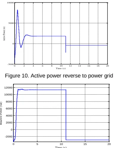
Figure 9 and 10 indicate active and reactive powers passed through static key in dq coordinate system. As it
can be seen, active and reactive powers of micro-grid after passing beginning fluctuations, is linear. Since in dq
coordinate system, power waves shape is linear, hence these wave shapes are suitable for power reverse
recognition system. This system is designed based on dq coordinate system. Figures 10 and 11 depict active and
reactive powers return respectively.
Figure 10. Active power reverse to power grid
Figure 11. Reactive power reverse to power grid
0 2 4 6 8 10 12 14 16 18 20
-5000 0
Time (s)
A
ct
ive
0 2 4 6 8 10 12 14 16 18 20 -2000
0 2000 4000 6000 8000 10000 12000
Time (s)
R
ea
ct
ive
P
ow
er
(
va
r)
0 2 4 6 8 10 12 14 16 18 20
-5000 0 5000 10000
Time (s)
A
ct
ive
P
ow
er
(w
)
0 5 10 15 20
-2000 0 2000 4000 6000 8000 10000 12000
Time (s)
R
ea
ct
ive
P
ow
er
(
va
731
According to figures 10 and 11, power reverse recognition system must be designed such that recognizes this recursion toward power grid and at the same moment, separates micro-grid from power grid.
Figure 12. Active power reverse to power grid and static switch performance
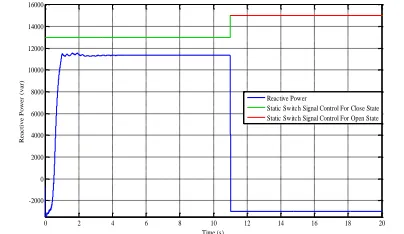
Figure 13. Reactive power reverse to power grid and static switch performance
Figures 12 and 13 represent performance of static switch against active and reactive powers return. As it is shown in figures 12 and 13, when power reverse towards power grid occurs, power reverse recognition system commands opening static switch by sending signal to switch. These two figures, depict appropriate precise performance of power reverse recognition system. Designed system detects active and reactive power and separates micro-grid from power grid in two modes.
CONCULSION
Since current and voltage wave shapes are sinusoidal, then active and reactive power wave shapes in time
domain are sinusoidal as well. But in dq coordinate system, active and reactive powers are linear, hence
appropriate precise design of power reverse system is according to power computations in dq coordinate system.
When power flow direction is from power grid to micro-grid, designed power reverse system has no activity and in contrast, this system was able to recognize power reverse from micro-grid to power grid and commanded static switch opening. Present system recognized active and reactive powers reverse in two cases and disconnected static switch in return case accurately.
REFERENCES
Rocabert Joan, Azevedo Gustavo MS, Luna Alvaro and Guerrero JM. 2011. Intelligent Connection Agent for Three-Phase Grid-Connected Micro-grids. IEEE Trans. Power Electronics. 26(10): 2993-3005.
Casey LF, Zubieta LE, Mossoba JT, Borowy BS and Semenov B. 2012. Power devices for grid connections. Power Semiconductor Devices and ICs (ISPSD), 24th International Symposium. 1-7.
Eloy-Garcia J, Vasquez JC and Guerrero JM. 2013. Grid simulator for power quality assessment of micro-grids. IET Power Electronics. 6(4): 1755-4535.
Mao M, Tao Y, Chang L, Zhao Y and Jin P. 2012. An intelligent static switch based on embedded system and its control method for a microgrid. IEEE Innovative Smart Grid Technologies - Asia (ISGT Asia). 1-6.
Perkins BK and Iravani MR. 1999. Dynamic modeling of high power static switching circuits in the dq-frame. IEEE Trans. Power System. 14(2): 678-684.
0 2 4 6 8 10 12 14 16 18 20 -6000
-4000 -2000 0 2000 4000 6000 8000 10000 12000
Time (s)
A
ct
ive
P
ow
er
(
w
)
Active Power
Static Switch Signal Control For Close State Static Switch Signal Control For Open State
0 2 4 6 8 10 12 14 16 18 20
-2000 0 2000 4000 6000 8000 10000 12000 14000 16000
Time (s)
R
e
a
c
ti
ve
P
ow
e
r
(va
r)
Reactive Power
732 Resources According to IEC 61850-7-420. IEEE Trans. Power System. 27(3): 1560-1567.
Ma J, Wang X, Zhang Y, Yang Q and Phadke AG. 2012. A novel adaptive current protection scheme for distribution systems with distributed generation. International Journal of Electrical Power & Energy Systems. 43(1): 136-142.
Ye Q, Ma T, Gu Y, Wang T, Wang D and Bai Y. 2012. Research on dispatch scheduling model of micro-grid with distributed energy. Electricity Distribution (CICED) China International Conference. 1-5.
Bellini P, Bruno I, Nesi P and Cenni D. 2012. Micro Grids for Scalable Media Computing and Intelligence in Distributed Scenarios. IEEE MultiMedia. 19(2): 69-79.
Illindala M, Siddiqui A, Venkataramanan G and Marnay C. 2007. Localized aggregation of diverse energy sources forrural electrification using microgrids. ASCE J. Energy Eng. 13(3): 121-131.
Kroposki B, Basso T and DeBlasio R. 2008. Microgrid standards and technologies. Power and Energy Society General Meeting. 20-24 .
Katiraei F, Iravani R, Ise T, Morozumi S, Dimeas A and Hatziargyriou N. 2008. Microgrids Management. IEEE Power and Energy Magazine. 6(3): 54-65.
Stevens J, Vollkommer H and Klapp D. 2007. CERTS Microgrid System Tests. IEEE Power Engineering Society General Meeting. 1-4.
Kato T, Suzuoki Y, Funabashi T, Cipcigan L and Taylor P. 2008. Microgrid Configuration for Major Network Events,” IET-CIRED. CIRED Seminar 23-24.
Bae I and Kim J. 2008. Reliability Evaluation of Customers in a Microgrid. IEEE Trans. Power System. 23(3): 1416-1422. Hatziargyriou N, Asano A, Iravani R and Marnay C. 2007. Microgrids. IEEE Power Energy Mag. 5(4): 78-94.
Abu-Sharkh S, Li R and Markvart T. 2005. Microgrids: distributed on-site generation. Tyndall Centre Technical Report. 22. Pes Lopes JA, Moreira CL and Madureira AG. 2005. Control Strategies for MicroGrids Emergency Operation. International
Conference Future Power System. 1-6.
Katiraei F and Iravani R. 2006. Power management strategies for a microgrid with multiple distributed generation units. IEEE Trans. Power System. 21(4): 1821-1831.