Protocol Coordination for Reliable Data Transfer and
Error handling in
MANET
# Tibabu Beza
Adama Science and Technology University Department of Computer science and Engineering
Abstract:
Mobile Ad-hoc Networks have been increasing their popularity in recent years due to ease of
deployment and low cost of its components. No infrastructure based network support is not required for
MANETS because each node communicates with other nodes though the radio frequency. The routing protocols
are challenged with establishing and maintaining multi-hop routes in the face of mobility, bandwidth and power
constraints. The services provided by the current technologies for multimedia transaction is not sufficient in
terms of quality of service and timely delivery of data. In this paper we tried to solve these type of problems by
proposing reliable data transfer protocol, which is capable of delivering multicast and unicast data in mobile
ad-hoc networks. The protocol has been designed to work on top of the IEEE 802.11 protocol without any
modifications in the hardware structure.
Keywords: Bandwidth, RDT, Mobility, IEEE
I. INTRODUCTION
In Mobile Ad-hoc Networks, the routing
protocols are challenged with establishing and
maintaining multi-hop routes due to frequent
mobility, bandwidth limitations and power
constraints. The bandwidth may be reduced due to
effects of multi-hop access, interference of signal
and channel fading.
Let us assume the system architecture
having set "S" of "n" mobile nodes which is capable
of communicating through the wireless
communication medium. i.e.
S = {x0, x1, x2 …… xn-1}
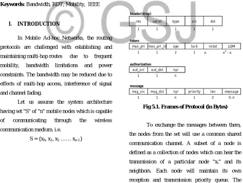
header(drop)
res serial type src dst
1 1 1 1 1
token
max_pri max_pri_id age lack nstat LQM
1 1 2 1 n n2 - n
authorization
aut_src aut_dst nyr
1 1 n
message
msg_src msg_dst nyr priority len message
1 1 n 1 2 0..n
Fig 5.1. Frames of Protocol (in Bytes)
To exchange the messages between them,
the nodes from the set will use a common shared
communication channel. A subset of a node is
defined as a collection of nodes which can hear the
transmission of a particular node "xi" and its
neighbors. Each node will maintain its own
reception and transmission priority queue. The GSJ: Volume 6, Issue 8, August 2018, Online: ISSN 2320-9186
priority may be from 0 to 127, where "0" is the
lowest priority and 127 is height priority level. Each
message exchanged between nodes will be based on
its priority. If any two messages having the same
priority level, then the messages will be transmitted
based on FIFO (First In First Out) order. When a
message is transmitted by an application from one
to another node, it will be placed in the transmission
queue. The wireless reliable data transfer (RDT)
protocol will insert the message into reception
queue by taking it from transmission queue. Finally
the application from the destination node it will pop
the message. This protocol generally works in
following three phases.
i. Priority Phase(PP)
ii. Authorization Phase(AP)
iii. Transmission Phase(TP)
This protocol check for the highest priority
messages at current situation in Priority phase.
During this phase, to reach the node which is having
highest priority message in the network at this
situation, a token travels through all the nodes. The
token holds the information like the level of priority
for the corresponding message and its owner from
the set of nodes. The node which initiates the
priority phaseindicates that the highest priority
message in its own queue and the same will be
updated in the token. After updating the token, it
will be send to another node. The receiver node will
check in its priority queue, whether any message
having highest priority than the priority in the token
which is transmitted by the sender, it updates the
token information and continue the phase. The same
process will continue until the token reaches to the
last node, which knows the identity of the
messagewhich is having the highest priority and
initiates the authorization process.
Subsequently an authorization to transmit is
sent to the node which is having the highest priority
in authorization phase. The node calculates the path
to the node which is having highest priority
message based on the topology information which is
shared among the members of the network and
sends the authorization message to the first ever
node in the path, from then to second node in the
corresponding path. Same will be continued until
authorization reaches to the node with highest
priority message. Then transmission phase was
initiated.
In the transmission phase, the message will
be transmitted to the destination node. The process
is similar to the one in authorization phase. The
node that has received the authorization calculates
the path to reach the destination. It sends the
message to the first ever node in the path then to
second node and finally to the destination node.
When transmission phase finished its operation then
the node in the destination initiates the Priority
phase again.
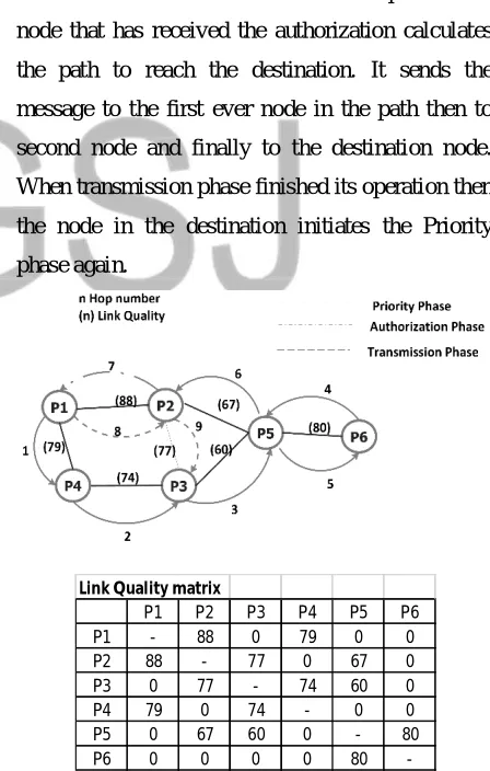
Fig 5.2 A hypothetical situation described by the network graph and the corresponding
LQM and the hops sequence of the protocol Link Quality matrix
P1 P2 P3 P4 P5 P6
P1 - 88 0 79 0 0
P2 88 - 77 0 67 0
P3 0 77 - 74 60 0
P4 79 0 74 - 0 0
P5 0 67 60 0 - 80
-II. LINK QUALITY MATRIX
The RDT protocol defines a network
connectivity graph to describe the topology of the
network. The network connectivity graph will
contain positive values on the edges of the graph.
These values are used to indicate radio signal and
link quality between them. We can represent these
values in the form of matric to make link quality
matrix. The values from the link quality matrix will
represents the link quality between the nodes Xi and
Xj. Each column in the link quality matrix will
represent the links of node Xk with its neighbors.
The signal strength may be different from
transmission to its reverse transmission i.e. the
signal received by Xi when Xj transmits may be
different from the signal received by Xj when Xi
transmits. Because of this, when it is computing the
path, it will select the minimum value from the set
of corresponding values.
lqmij(min) = min(lqmij, lqmji)
The elements of the link quality matrix are
functions of the radio signal links between nodes.
To calculate them, we use the received signal
strength indicator (RSSI) defined by the 802.11
protocol. The physical sublayer measures the energy
observed at the antenna used to receive the current
frame. The 802.11 devices provide this value to the
device driver. Some card models provide
information on noise as well. With these two
parameters, we can estimate the signal to noise
ratio(SNR) for every frame received and estimate
link quality between nodes, representing it with
values in the [0,max_lq] range. The calculation of
the path in the authorization and transmission
phases is based on these values. The Dijkstra
algorithm for the single source shortest path
problem for directed graphs with nonnegative edge
weights is applied to the graph that represents the
matrix M, derived by means of a simple heuristic
from the link quality matrix.
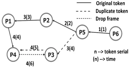
Fig 5.3. Token duplication resolution
mechanism. In case of message or authorization
duplication the mechanism works in similar way
III.DEFINING FRAMES
The frames may be divided into two parts
called primary and secondary data as shown in fig
5.1. The primary data may be treated as header and
which is common to all frames. The secondary data
is different from one to others based on frame type.
If we consider the frame format, the first byte with
the field name "res" is reserved to establish the
communication between the reliable data
transmission (RDT) protocol and network interface
card (NIC). The serial number of the frame will be
holds by "serial" field and this field is used in
mechanism to recover the errors along with the third
field "retries" which is having the capacity 1 byte.
The next field "type" represents the type of frame.
The last two fields "src" and "dst" are used to
represent the source and destination addresses of the
frame. In general, the RDT address will be
identified by the nodes through the range 0 to n-1.
When a frame was transmitted by a node, it has to
fill the source and destination addresses in the
header with its RDT address and RDT destination
address before broadcasting the frame. When a node
broadcast the frame, all the neighbors can hear the
frame due to shared radio signal but, only the
The "token" frame adds the highest priority
and its id in the first two fields with the size of 1
byte each. The third field "age" generally used to
check and hold the oldest message in the message
queue with the same priority level. To keep track of
acknowledgements of frames which are transmitted
in the last transaction, the "lack" field is used. The
next field "nstat" represents the status like whether
the frame was reached, not reached, lost or searched
of a particular node. For example, nstat[i] used to
represent the status of node pi. The last field "LQM"
in the token holds information of link quality
matrix.
The authorization frame adds the address of
source and destination of the authorization. It also
adds the value of "nyr" variable with the field length
of 1 byte, which also used to avoid the infinite loops
in message delivery stage and at the authorization
stage. The message frame adds the RDT address of
the source and the destination. The "priority" field
holds the priority of the message and "len" fields
holds the amount of data carried and its priority by
the particular frame. The "data" field used to
represent the payload of the frame and finally the
last field "drop" is a simple header and can be
identified by "type" field.
IV.PROTOCOL PHASES
In this section we described the three phases
of protocols in detail. we described the protocol
phases with the assumption that the network is
connected, all the nodes know the network
topology.
A. Priority Phase
In this phase, when node Xkinitiates the
priority phase process, it creates a new token and
copies it local LQM value in the respective field in
the token, sets nstat[i] to "unreached" and nstat[k]
will be set to "reached" initially. The value nstat[k]
is set to "reached" means except the node Xk, the
token has not reached to any other nodes in the
current situation.
For All i belongs to [0, n-1] ;i ≠ k.
Afterwards, the token checks the priority
level of highest priority message in the transmission
queue then appends the corresponding values in the
fields "max_pri" and "max-pri-id". The "max-pri"
fields holds the value and "max-pri-id" field holds
the address of RDT. The "age" field represents the
waiting time of a message in the queue, i.e. the time
spent in milli-seconds in the message queue up to
that moment. By this way the node Xk becomes the
highest priority message holder. Then it analyzes
the link quality matrix to know which node is
sharing the best quality link with it. Once the best
quality link was obtained, sends the token to it. Let
us assume the node Xij receives the token, it sets the
nstat[ij] to reached and update the link quality
matrix token with its local data and saves the matrix
locally. Once the matrix was saved, it increases the
"age" field by a quantity equal to the duration of
one token-pass hop. Then it looks for the highest
priority field i.e. "max-pri" of the token and this
value is compared with the priority value of the
most highest priority message in its queue. If it
founds any highest priority message from the queue,
it updates "max-pri" and "max-pri-id" fields. If it
holds a message with the same priority, it updates
the token. Consequently, it will select the not yet
reached node from the set of nodes with which it
shares the best link quality, and sends the token to
it. If a node only listens to the node from where it
receives the token, it can return the token to the
node from where it receives after updating. By this
we can understand that a node can receive the token
case, it has right to update the "max-pri" and "
max-pri-id" values. This scenario helps to reduce the
well-known priority inversion problem. The same
process is repeat until all the nodes have been
reached by the token.
nstat[i]=reached foralli
The last node to receive the token knows
the highest priority message holder identity, i.e.
which contained the highest priority in its "
max-pri-id"field and is responsible for sending the
authorization to it.
B. Authorization Phase
The node which initiates authentication
process will calculate a path to the destination node.
To calculate the path, the node applies well known
Dijkstra algorithm to a distance matrix derived from
the link quality matrix. This algorithm returns a path
to the destination as a set of nodes represented by X
= {Xx1, Xx2 … Xxn}. Then the node creates an
authorization and update the "aut-src" and "
aut-dest" fields with the highest priority message holder
address and its own address respectively and start
sending the authorization to the first node "Xx1" in
the path. When "Xx1" recieves the authorization, it
looks at the field "aut-dest" and if it contains the
address, it ends the authorization process otherwise,
it calculates the following path
X1 = {X1x1, X 1
x2 … X 1
x(n-1)} Where X 1
xk = Xx(k+1) k<n
i.e. since the calculation is executed over
the same link quality matrix, the path calculated will
be the same except that the first hop has already
taken place. The same topological information is
available with each node and due to this, the
bandwidth will be saved at the time of recalculation
of the path in each hop. The node repeats the
process, routing the message to the next member of
the path, leaving the "aut-dest" field without any
changes.
C. Transmission Phase
When the highest priority message holder
receives the authorization to transmit, it takes the
highest priority message out from its transmission
queue and creates a new message frame and places
the data in the "data" field. It fills the "msg-src" and
"msg-dest" fields with its address along with the
destination address and calculates the path to the
destination. Then it fills the fields "priority" and
"len" with the message priority and data length and
sends it to the first node in the path. When later
receives the message, it checks the field "msg-dest".
If it contains the address of the destination, it
appends the message into the queue of recipient and
starts a new priority phase. Otherwise, it will
continue with the path computation and repeats the
process, the message is then routed to the next
member which is available in the path and leaving
the "msg-dest" field without any modifications.
V. ERROR HANDLING
For any protocol, we need to manage the
possible reasons to get the errors. Similarly this
protocol also have two possible reasons to get the
error, they are either node failure or communication
error. The node failure is occurred frequently in all
the networks and the communication error will
occur especially in wireless networks. This protocol
was designed for error recovery not only in the case
of real time behavior but also network topology in
most of the cases when error occurs.
A. Node Failure
When a token is transmitting from source to
destination with explicit acknowledgement, the
form of message to the sender. Let us assume after
receiving the token by the receiver, it sends an
acknowledgement to the sender node, but if the
node has failed immediately after transmitting the
acknowledgement by the sender to receiver, the
token is lost and it needs the regeneration of the
token to retransmit. In RDT, when a node Xk sends
a frame of any type to the node Xp, it listens to the
channel for timeout. The receiver node Xp will
process the frame received and sends it to the next
immediate node Xq. The first sender listens to such
a frame as well and interprets it as an
acknowledgement. This technique permits saving of
bandwidth and eliminates the need for monitor
node. In any case, if the first sender does not hear
the frame with in the specified time or timeout, it
supposes that the node Xp has failed or is out of its
coverage area. In this case, the behavior depends on
the phase that the protocol is in. If it is in the
Authorization or transmission phase, the node Xk
discards the frame and starts a new priority phase. If
it is in the priority phase, the Xk sets the nstat[p]
field to "reached", and modifies the local link
quality matrix, the link quality matrix carried by the
token to exclude the node Xp from the set of its
neighbors by setting lqmkp = 0 and continues with
the priority phase, sending the token to the another
node. This solution excludes the node Xp in the
current priority phase to preserve network
temporization but not necessarily in the next priority
phase. If the node Xp has not actually failed but let
us assume, has moved away from the node Xkbut
not from another neighbor Xq, the latter will reinsert
the node Xp in the next priority phase by simply
passing it the token with any additional cost. If the
node Xpreally broken or has moved away from all
other nodes, in the next priority phase all its
neighbors will try to pass the token to it one after
the another until the node Xp is isolated. When this
occurs, the node that starts the next priority phase
identify this node as lost setting
nstat[p] = lost + r where 0≤ r < n and Xr does not belong to the set of nodes
B. Reinsertion of lost node:
The number ' r ' represents the identification
of lost node to search in the current priority phase.
If any node is reappeared, it is impossible predict
the node location. Simultaneously, the nodes will be
organized themselves those still belongs to the
network to search for the lost node one after another
in the successive priority phase. When the node Xr
receives the token, it looks at the nstat array. If one
of the elements contains the value lost + r, it tries to
send the token to Xp. If the later acknowledges the
frame, it is reinserted in the network with no
additional cost. Otherwise, the node Xrsets nstat[p]
= searched + r and continues the priority phase. No
other nodes try to search for that node in the current
priority phase, since this would break the network
temporization. The node that starts the next priority
phase modifies the field nstat[p] = lost + ((r + 1)
mod n) if X(r+1) mod nnode is not a lost node and
continues the same phase. Like this all the nodes not
lost will search for the lost node one after another in
the successive priority phase of the node take place.
C. Frame Duplication
Let us consider the scenario where, in the
priority phase, the node Xk sends a token to the
node Xq and waits for an implicit acknowledgement.
The node Xq processes the frame and sends the
frame to the node Xr. As we discussed in the last
section, the last pass is also the acknowledgement
for the node Xk. If the node Xr hears the frame but
Xk does not, a token duplication occurs. In fact, the
the priority phase by sending the token to another
node. The node Xr continues the priority phase as
well and at that moment there are two token in the
network. To solve this problem we introduced the
serial field in the frames. This contains a value that
is set to zero when the first priority phase begins.
Before each transmission, the sender node increases
this value, saves it locally, and then transmits. The
node will discard the frame and informs the sender
by sending drop frame when it receives a lower
serial frame or equal to the highest serial that it has
transmitted. In figure 5.3 an example situation is
presented. Theauthorization or message duplication
can occur in the same way. In keeping with the
behavior, the unacknowledged node discards the
message or authorization and creates the new token
frame. The receiver of the authorization / message
continues to route the frame along the path. At that
moment there are two distinct type of frame
travelling in the network. Just as in the case of
simple token duplication, the first node that receives
a frame with an old serial will discard it.
D. Frame Retransmission
It is possible to retransmit the frame in this
protocol. When a node sends a frame but does not
receive an implicit acknowledgement within
timeout, it can reattempt the transmission a fixed
number of times. The use of this capacity can
provoke in some situations, similar problems to
frame duplication. Let us consider the scenario in
which node Xk sends a frame to the node Xq and the
latter to node Xr that will receive a duplicated frame
that should not propagate. In this case the node Xq
recognizes that it is the same frame looking at the
serial and retry fields and send a drop frame back to
the node Xk that is informed, in this way, that it
must discard the frame. On the other side, this
capability alerts the real time timing of the protocols
and must be considered at the planning time since
each transmission can entail n retransmissions.
VI.PERFORMANCE EVALUATION
To evaluate the performance of the
protocol, we tested the various characteristics to
check whether the protocol was implemented
correctly or not.
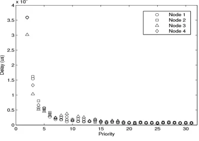
A. Behavior
We considered various behavioral
characters to measure the performance of the
protocol. Among them the first was priority based
message exchange mechanism. For this we
considered the four node network with heavy traffic
generated at every node. The nodes have a
transmission priority queue of 20 messages and
each message will have a priority between 0 and 31
randomly. In each node, the messages with high
priority had shorter delays and the nodes
thosehaving low priority with longer delays. This
observation is shown in figure 5.4.
Fig 5.4. Priority behavior of the protocol
We conducted another experiment which
concerns the fairness of the protocol. In this we
considered the messages with equal priority at every
node. The aim was to verify that all the nodes had
the same chances of sending their messages. i.e. all
their entry in the queue and their exit. The figure 5.5
shows the results of this experiment and fulfils the
requirement.
Fig 5.5 Fairness of the protocol
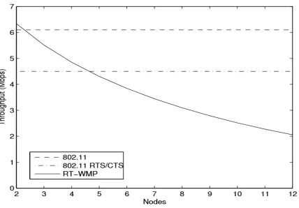
B. Throughput
We performed two experiments for reliable
end to end throughput of the protocol. In both the
cases the underlying 802.11 protocol network rate
was 11Mbps. For the best case, we created a
completely connected network of two, three and
four nodes with high traffic at each node. In this
situation the priority phase always lasted n-1 hops,
the authorization phase have zero or one hop and
the transmission phase lasted one hop. To determine
the effective instantaneous bandwidth, we divided
the payload of a message by the time lapse
measured between the creation of new token and the
delivery of the corresponding message.
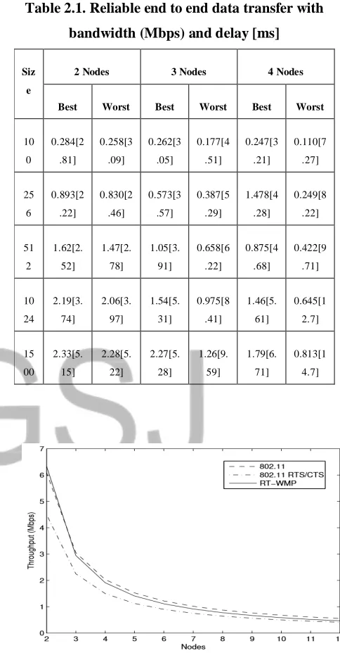
To test the throughput in the worst case
situation, the priority phase always lasted 2n-3 hops,
the authorization phase and the transmission phase
lasted n-1 hops. We performed three tests with n
equal to two, three and four nodes. We provided the
nodes with fake LQM to simulate a chain of two,
three and four nodes respectively and heavy traffic
was generated in all the nodes. We calculated the
effective instantaneous bandwidth just as we did in
the best case but this time only taking into account
the intervals in which the worst case situation
occurred. The results are shown in the table 2.1 with
the details of bandwidth and delay in milli-seconds.
Table 2.1. Reliable end to end data transfer with
bandwidth (Mbps) and delay [ms]
Siz
e
2 Nodes 3 Nodes 4 Nodes
Best Worst Best Worst Best Worst
10 0 0.284[2 .81] 0.258[3 .09] 0.262[3 .05] 0.177[4 .51] 0.247[3 .21] 0.110[7 .27] 25 6 0.893[2 .22] 0.830[2 .46] 0.573[3 .57] 0.387[5 .29] 1.478[4 .28] 0.249[8 .22] 51 2 1.62[2. 52] 1.47[2. 78] 1.05[3. 91] 0.658[6 .22] 0.875[4 .68] 0.422[9 .71] 10 24 2.19[3. 74] 2.06[3. 97] 1.54[5. 31] 0.975[8 .41] 1.46[5. 61] 0.645[1 2.7] 15 00 2.33[5. 15] 2.28[5. 22] 2.27[5. 28] 1.26[9. 59] 1.79[6. 71] 0.813[1 4.7]
Fig 5.6. Comparison of RDT and 802.11 for the
Fig 5.7. Comparison of RDT and 802.11 for the
best case situation
VII. CONCLUSION
We introduced the features of RDT
protocol, which can work over 802.11 based
networks providing reliable data transfer support. It
uses the token passing mechanism to provide
guaranteed transmission times using the message
priorities. This protocol deals with the frequent
topology changes through the link quality matrix by
sharing amongst the nodes. We also discussed the
error recovery and management issues when
multiple failures occurred during its transmission in
mobile ad-hoc networks. The results are analyzed
with 802.11 protocol in worst and best case
situation.
REFERENCES
1. Prashant Singh and D. K. Lobiyal, “DSR
with link prediction using Pareto distribution
IEEE International Conference on
Networking and Information Technology,
pp. 29−33, 2010.
2. V. Ramasubramanian, Z.J. Haas, and E.G.
Sirer, “SHARP: A Hybrid Adaptive Routing
Protocol for Mobile Ad Hoc Networks,”
Proc. ACM International Symposium on
Mobile Ad Hoc Networking and Computing
(MobiHoc 2003), pp. 303-314, 2003.
3. C.E. Perkins, P.R. Bhagwat, “Highly
dynamic destination sequences distance
vector routing (DSDV) for mobile
computers”, Proceedings of ACM
SIGCOMM, pp. 234−244, 1994.
4. D.B. Jonhson, D.A. Maltz, “Dynamic Source
Routing in Adhoc wireless networks, Mobile
Computing”, T. ImieLinski and H. Korth,
Eds. Kluwer Academic Publishers, Vol. 353,
pp. 153−181, 1996.
5. C.E. Perkins, E.M. Royer, S. Das, “Adhoc
on Demand Distance Vector Routing”,
Proceedings of Second IEEE workshop on
Mobile Computing Systems and
applications, pp. 90−100, 1999.
6. V. Park. S. Corson, “Temporally Ordered
Routing Algorithm (TORA) version 1”,
IETF Internet Draft
(draft-ietf-manet-tora-spec-04.txt), July 2001.
7. L. Kleinrock, F. A. Tobagi, “Packet
switching in radio channels: Part II-the
hidden terminal problem in carrier sense
multiple access and busy tone solution”,
IEEE Transaction Communications, Vol.23,
no. 12, pp. 1417−1433, 23rd December
1975.
8. C. K. Toh, Adhoc Mobile Wireless
Networks: Protocols and Systems,
Prentice-Hall PTR, NJ, 2002.
9. P. Karn, “MACA: a new channel access
method for packet radio”, Proceedings of the
ARRL/CRRL Amateur Radio 9th Computer
Networking Conference, September 22,
10. V. Bhargavan, A. darners, S. Shenker,
L. Zhang, “MACAW - A Wireless Media
Access protocol for Wireless Lans”,
Proceedings of ACM SIGCOMM, pp.
212−225,1994.
11. C. Wu, V.O.K. Li, “Receiver-Initiated
Busy-Tone Multiple Access in packet radio
networks”, Proceedings of the ACM
SIGCOMM ’87 Conference, pp. 336−342,
1987.
12. Z.J. Haas, J. Deng, “Dual Busy tone
Multiple Access (DBTMA) - a multiple
access control scheme for adhoc networks”,
IEEE Transaction Communications, Vol. 50,