_____________________________________________________________________________________________________ 13(4): 1-14, 2018; Article no.ACRI.40031
ISSN: 2454-7077
Design of a Central Wireless Security System Using
Atmega328, ZigBee and Arduino
Olumuyiwa O. Fagbohun
1*and Oyeyemi Mayowa Fagbohun
21Department of Electrical and Electronic Engineering, Ekiti State University, Ado-Ekiti, Ekiti State, Nigeria. 2
Department of Electrical and Electronic Engineering, Osun State University, Osogbo, Osun State, Nigeria.
Authors’ contributions
This work was carried out in collaboration between both authors. Author OOF designed the study, wrote the protocol and final draft of the manuscript. Author OMF managed the analyses of the study and the literature searches. Both authors read and approved the final manuscript.
Article Information
DOI:10.9734/ACRI/2018/40031
Editor(s):
(1) Grigorios L. Kyriakopoulos, School of Electrical and Computer Engineering, National Technical University of Athens (NTUA), Greece. (2) Tatyana A. Komleva, Department of Mathematics, Odessa State Academy of Civil Engineering and Architecture, Ukraine.
Reviewers:
(1) Amit Kumar Mondal, University of Petroleum and Energy Studies, India. (2) Leonardo Barboni, Universidad de la República, Uruguay. (3) Ángel P. de Madrid, Univeridad Nacional de Educación a Distancia (UNED), Spain. (4)Hung-Yu Chien, National ChiNan University, Taiwan. (5)Harpreet Singh, Lovely Professional University, India. Complete Peer review History: http://www.sciencedomain.org/review-history/24248
Received 9th February 2018 Accepted 15th April 2018 Published 20th April 2018
ABSTRACT
Security of life and properties is one of the basic provisions of a nations constitution which must be well protected at all times. For residential and industrial setups, there are so many security infractions that needed better solutions taken the advantages of the new developments in Communication technology. This work intends to provide a security system to monitor a residential or industrial setup, for infractions and give the necessary information to arrest its effect even without the physical presence of the property owner. The design consists of wireless sensor network for surveillance in a typical residential or industrial outfit using ZigBee wireless communication protocol, while the ATTiny102 microcontroller was used as the controller for the sensor and security module. The information from the ZigBee wireless device was transmitted through a radio frequency signal at 2460 MHz to the central processing unit with ATmega328p
microcontroller to give information received through a buzzer alarm and SMS notification including an LCD display. The result shows a cost-effective means of securing a property at all times, while giving a clear reception of signals at distance of < 500 m from the central controlling unit, with total harmonic distortion [THD] calculated as 2.37%, and the measured THD with the use of a distortion analyzer between 1.29% and 3.63% at a separated distance of 500 m. The signal noise was calculated as 1.79dB, while the measured signal noise was 1.52dB and 2.34dB. The signal strength is about 72% of the maximum derivable of -42.7dBm from the system propagation at 500m distance apart, while the efficiency is calculated to be 96.7% with ease of maintenance due to few components used.
Keywords: Central wireless security system; ZigBee module; Arduino; ATmega328 microcontroller.
1. INTRODUCTION
Security of residential and industrial environment can be achieved through various physical and electronic means. In the use of electronics, a CCTV and IP camera systems provide excellent quality pictures in both daylight and darkness, easy and flexible to use and provide high quality images for recording evidence or help analyze an event [1,2]. For deterrence, the potential burglars and thieves may see the camera and decide that the residence or store in question is too much a risk and therefore not a good target. In prosecution, thieves and shop lifters may be caught on the camera and this can help catch and prosecute them. CCTV is equally used to reduce fear of attack in that, if everyone knows that there is a camera they may feel safer in or around a business thus preventing potential criminals from attacking [2].In monitoring and intervention, if there is a security guard monitoring the area under CCTV and IP camera system he or she may act on any suspicious behavior and thus prevent crime from occurring, security guards may also deploy employees to a suspicious spot or near a person detected on the monitor [2,3].
Another means of securing a property from attack or damage is the use of alarm system. This is a device or system that gives an audible, visual or other form of alarm signal about a problem or condition [2]. Burglar alarms are designed to warn of burglars, often a silent alarm, which can alert the police or guard without indication to the burglar which increases the chance of catching him or her. A burglar system is designed to detect intrusion or an un-authorized entry into a building or area [2,3]. Burglar system are used in residential, commercial, industrial and military properties for protection against burglary(theft) or property damage, as well as personal protection against intruders.
The most basic alarm consists of one or more sensors to detect intruders, and an alerting device to indicate the intrusion. Sensors may be placed at the perimeter of the protected area, within it, or both. Sensors can detect intruders by a variety of methods, such as monitoring doors and windows for opening, or by monitoring unoccupied interiors for motions, sound, vibration, or other disturbances [4,5].
emitting an ultrasonic signal into the area to be protected [8]. The sound waves are reflected by solid objects (such as the surrounding floor, walls and ceiling) and then detected by the receiver. Because ultrasonic waves are transmitted through air, then hard-surfaced objects tend to reflect most of the ultrasonic energy, while soft surfaces tend to absorb most energy. When the surfaces are stationary, the frequency of the waves detected by the receiver will be equal to the transmitted frequency. However, a change in frequency will occur as a result of the Doppler principle, when a person or object is moving towards or away from the detector. Such an event initiates an alarm signal. This technology is
considered obsolete by many alarm
professionals and is not actively installed.
Security alarms are often coupled with a monitoring service. In the event of an alarm, the premises control unit contacts a central monitoring station. Operators at the station see the signal and take appropriate action, such as contacting property owners, notifying police, or dispatching private security forces. Such signals may be transmitted via dedicated alarm circuits, telephone lines, or Internet alarm connection and monitoring. Depending upon the application, the alarm output may be local, remote or a combination. Local alarms do not include monitoring, though may include indoor and/or outdoor sounders (e.g. motorized bell or electronic siren) and lights (e.g. strobe light) which may be useful for signaling an evacuation notice for people during fire alarms, or where one hopes to scare off an amateur burglar quickly [2,3,7].
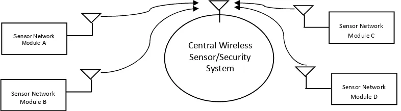
Electronic Security System for residential and industrial monitoring of events and actions is achieved by strategically installing sensors and security devices like motion sensors, smoke sensor, security cameras, temperature and humidity sensors at different locations. The group of individual sensor and security system then communicates its data to a central hub (Central Security System) through either wired or wireless (ZigBee) communication protocol for processing [8,9,10].
Wireless Security System is designed to keep people, valuables and property secured from danger. Whether installed in a house or apartment, Wireless Security System can protect against harmful scenario that can unfortunately arise no matter where you live. Wireless Security System offers surveillance systems with home
security cameras, alarm systems that monitor smoke or carbon monoxide levels [10,11,12], professional monitoring with a control station, and may even help to reduce energy consumption; professional monitored home may provide some or all of the following equipment: a control panel to adjust users settings or security preferences from any location; sensors on
windows and a door; and surveillance devices, sirens or alarm to notify the police and / or fire department, a central monitoring
station, the home owner and neighbor, motion detector, and wireless hour security sticker to adhere to a window or a sign to place in one yard.
A home security and surveillance system is an essential part of any modern home. The basic design of a security system begins with analyzing the needs of the inhabitants, surveying existing technology and hardware, reviewing system cost, considering monitoring choices and finally planning the installation [12]. The wireless Home Security System can potentially deter theft caused by burglar or home invasion. The single act of installing sensors on windows and doors can alert home owners of a break–in before a burglar attack is successful [1,5,7]. Motion sensors that monitors entry points on the property can also be programmed to notify Home Security System subscribers of any unwanted activity on their property. In addition, placing a wireless Home Security System yard sign on properties or affixing Home Security System stickers on doors can alert would–be robbers that the property is protected from unwanted entry. Also, with the use of carbon monoxide detector, the deadly odorless and colorless gas which is highly toxic to both humans and animals when inhaled can be detected easily in an apartment; as well as smoke with the use of smoke detectors [1,5]. A wireless Home Security System connected to Wi-Fi may come with functionality to save money, time and energy in which energy serving programs are embedded to manage the heating and cooling preferences. This advanced energy management system can remotely control the turn on/off of air conditioning when one is not at home [5,6].
your home via security cameras, control door locks, lights and other devices remotely, as well as home security systems which alerts you of fire and gas problems, which makes room for peace of mind.
The disadvantages of household security systems include cost, for security systems are generally expensive, i.e., The cost of purchase and cost of installation is very high. Installation is mostly doneby experts in the field and some security systems are susceptible to signal interference. Segregated security systems are usually associated with issues of latency and complex management [7]. These systems require higher cost of installation and maintenance and the ratio of cost to accuracy in traditional security systems is relatively high compared to the efficiency of the system in general [7].
Thus, the aim and objective of this paper are to design a cost-effective, easy to install, efficient and scalable wireless electronic security system that interacts with groups of sensors and security devices installed at different locations and analyse the data gotten from such sensors to make appropriate decisions.
2. MATERIALS AND METHODS
The components and software used for the design of the central wireless security device include both the hardware and software.
2.1 Hardware Components
ATmega328P (Microcontroller used for the central system)
ATtiny102 (Microcontroller used in the sensor group module)
DRF1605H ZigBee module (Wireless communication module)
16 X 2 alphanumeric liquid crystal display Passive Infrared motion sensors
Digital gates (AND, OR gates) NE555 timer
Voltage regulators (LM7812, LM7805 and LM1117-3.3)
Other active and passive components (Resistors, Capacitors, Transistors etc.)
2.2 Software Components
Arduino (Embedded software platform) ZigBee wireless communication stack ZigBee configuration tool
2.3 Design of a Central Sensor Network
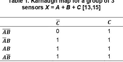
All schematic design in this paper was designed using Proteus Design Suite 8.3. The basic structure is illustrated in the block diagram in Fig. 1a, 1b and 1c which describes the information and signal flow. For the wired interface, a set of related sensors are grouped together with a gate i.e. sensors in close proximity to each other are grouped together. Each group of sensors is connected to an OR gate, so that when any of the sensors in a group is HIGH the output signal is HIGH. Table 1 describes the signal coding for a group with three sensors [13,14].
Table 1. Karnaugh map for a group of 3 sensors X = A + B + C [13,15]
0 1
1 1
1 1
1 1
The ATtiny-102 microcontroller is programmed to detect the voltage transition at the output of the OR gate for decision making. Such voltage transitions translate to sensor triggers when certain “normal” conditions are not met or broken. The ATtiny102 is a small, versatile, low-cost and easy to use high-performance 8-bit RISC-based microcontroller produced by Microchip. This microcontroller combines 1KB in-system programmable Flash memory, 32 Bytes of SRAM and six general-purpose I/O lines. It also features a full duplex USART, 10-bytes unique ID (serial number) and software selectable power saving modes. The USART provides a means for wired or wireless interfaces, making it possible to create a powerful yet small and low-cost solution for all types of Internet of Things (IOT) end-nodes [14,15,16].
There are several ZigBee compliant modules on the market made from different manufacturers. A DRF1605H ZigBee module from DTK electronics is used, which is a long range wireless serial module that implements the ZigBee2007 protocol with a visual communication distance of 1600 meters [12,18,19]. This module has a standard input voltage range of 2.6V – 3.6V and radio frequency ranges of 2405MHz – 2480MHz which can be changed in a step of 5MHz. The module supports transparent and command mode data transmission and has an automatic mesh networking feature inbuilt. For two ZigBee wireless module to establish connection, they must have the same PAN ID and communicate at the same BAUD rate [12,19]. A ZigBee configuration tool is used to configure the PAN ID and BAUD rate of this module. This makes the wireless network addressing system very simple.
The transmitted data is then received by the central wireless and security system module through its DRF1605 ZigBee transceiver [19]. This data is directly channelled to the transceivers UART port (As a wireless serial communication module) which is connected to an ATmega328p’s UART port [16,19]. The
ATmega328P is a low-power CMOS
(Complementary Metal Oxide Semiconductor)
8-bit microcontroller based on the AVR enhanced RISC (Reduced Instruction Set Computer) architecture. By executing powerful instructions in a single clock cycle, the ATmega328P achieves throughputs approaching 1 million instructions per second(MIPS), per MHz allowing the system developer to optimize power consumption versus processing speed. The ATmega328P has 32Kbytes flash, 1Kbyte EEPROM and 2Kbytes of RAM [19]. The architecture of this microcontroller makes it achieve throughputs of up to ten times compared to conventional CISC microcontrollers [16,18,19].
There are different methods and approach to programming the ATmega328p microcontroller just like most AVR microcontrollers. For this project, this microcontroller was programmed with Arduino as it aids easy and fast development.
Arduino is an open source, computer hardware and software company, project, and user community that designs and manufactures microcontroller kits for building digital devices and interactive objects that can sense and control objects in the physical world [20]. The project's products are distributed as open-source hardware and software, which are licensed under
Fig. 1a. Block diagram of the sensor network module to be designed [9]
Fig. 1b. Block diagram of the central wireless sensor and security system to be designed [9]
ZigBee
Serial Wireless Device
ATMega328-PU
Microcontroller
Output
-LCD Display -Buzzer Alarm -SMS Notification RF
UART
Inputs
-Burglar detection sensor -Fire/Gas leakage sensors -PIR sensors etc.
ATTiny102
Microcontroller
ZigBee
Serial Wireless Device
RF
Fig. 1c. Block diagram of the complete system (Central wireless security system)
the GNU Lesser General Public License (LGPL) [16,20]. Arduino, as referred to in this paper, is the software development platform used to program the ATmega328P microcontroller which has been pre-boot loaded with Arduino firmware [16,20].
The microcontrollers (ATMega-328P and ATTint102) requires an appropriate firmware to run effectively. The firmware acts as a link between the hardware (Microcontroller) and the
embedded software. In the arduino
environment/community, this firmware is also known as the bootloader. Since Arduino was used with this microcontrollers, then an Arduino bootloader must be written to these microcontrollers. This serves two critical purpose [14,16,20];
i. Makes the microcontroller to be programmed through its serial (UART) port ii. Pre-configures the microcontroller (Setting appropriate fuse bits) to Arduino specification with the most important and relevant being to use an external 16MHz crystal oscillator instead of its internal 8MHz oscillator [16,20].
The data represented in the truth Table 2 form the bases for decision making when writing the embedded software. From the truth Table 2, it can be seen that if at least one sensor out of a group of sensors should send a HIGH signal to the central security hub, it is assumed that something associated with that group went wrong.
The activity diagram of the wireless sensor module shown in Fig. 2a describes the programming pattern of the code embedded in the ATTiny102 microcontroller, in which the coded signal representing the actual sensed signal/transition is transmitted through the wireless network with the use of the DRF1605H ZigBee wireless module and received by the
ZigBee wireless module [21,22] of the Central wireless security system developed as shown in Fig. 2b. This well-defined state change was used to program the ATtiny-102 microcontroller to detect such voltage transitions (from LOW to HIGH) and transmits a coded message to the central controller describing the sensed transition. The central security system can then take actions such as triggering of alarms and display of alert messages [23,24].
Table 2. Truth table describing a group of three sensors [13,15]
SensorA Sensor B Sensor C Output = A + B + C
0 0 0 0
0 0 1 1
0 1 0 1
0 1 1 1
1 0 0 1
1 0 1 1
1 1 0 1
1 1 1 1
The ATtiny-102 microcontroller serves as the programmed input and output control interface for the wireless sensor module. It interfaces with the ZigBee serial wireless module through its UART communication port to transmit some coded data wirelessly to the central security unit to take prompt action. The overall output of the digital OR gate was connected to a digital input and output pin PA1 on the microcontroller which was configured programmatically as an input pin. This pin continuously monitors the output of the digital gate for a voltage transition (from LOW to HIGH) as configured. The output switch 1 and 2 are connected to digital output pins PA0 and PB1 through the base of their individual transistor Q1 and Q2 to switch ON or OFF external electronic devices like digital cameras, panic alarming systems and the likes [23,24].
Sensor Network Module A
Sensor Network Module B
Sensor Network Module C
Sensor Network Module D
Central Wireless Sensor/Security
The coded signal received is then processed by an ATmega328p microcontroller to display an alert message and activate the continuous panic alarm circuit.
The schematic design shown in Fig. 4 below describes the control, display and serial communication link for the central wireless security system. As shown in the schematic in Fig.4, the ATmega328 IC serves as the
programmed interface connecting and controlling the liquid crystal display, the central panic alarm system and the ZigBee serial wireless communication module [19].
The design was simulated with two output interfaces i.e. an LCD and a speaker, and an
array of input interfaces grouped with sets of OR-Gates (as shown in the Schematic Sheet 1).
Fig. 2a. Activity flowchart diagram of the sensor network module [22,23]
Fig. 2b. Activity flowchart diagram of a central wireless module [22,23]
START
Sensor network module All sensors are active high
Get sensor inputs from gates
If any sensor is high
Send a coded signal through the wireless network to the central
security system
STOP
Yes
No
A
SMS Owner of Property
Receive coded signal through the wireless network from the
wireless sensor module
START
Central wireless security system
Activate Panic alarm
Display sensor group error
Fig. 3. Schematic design of the wireless sensor module [13,15]
Push buttons were used in place of sensor inputs to simulate the digital logic inputs from such sensors as shown in Fig. 3. Similar sensors were grouped together and connected to OR gates so that when the signal level of any of such sensor changes from a LOW state to a HIGH state, the overall signal level of the gate will go HIGH i.e. The output signal equals to the logic sum [14,15] of all its input
OUTPUT = S1 + S2 + S3 + ……. + SN
Where:
S = Signal level of each connected sensor N = Number of connected sensors
The output from the liquid crystal display was simulated with the wireless security sensor module connected and tagged with Passive Infrared (PIR) sensors for intruder door alarm, gas leakage sensors. When an object, such as a human, passes in front of the PIR sensor the temperature at that point in the sensor's field of view will rise from room temperature to body temperature, and then back again. The sensor converts the resulting change in the incoming infrared radiation into a change in the output voltage, and this triggers the detection. In the cause of simulation, the alarm output which was driven by an NE555 timer was controlled through a digital pin tagged ‘ALARM' from the ATMega328 microcontroller. Fig. 5 shows a schematic of an NE555 timer to generate signal pulses to drive a loudspeaker [25]. This circuit is directly controlled and connected to the ATmega328 on the central wireless security module through the pin tagged “ALARM” [16,21,22].
The continuous alarm circuit is activated when the central security module receives a panic signal from any of the connected sensor module. The rate of this pulse i.e. the frequency of the continuous alarm circuit is determined by R1, R2
and C3. The value of R1, R2 and C3 was calculated using the formula below to give an output frequency of 520Hz.If R1 = R2 = R, f = 520Hz and C = 47uF is substituted in the equation below
= .
( ) =
.
and = .
Therefore, R = 19.6Ω
The alarm is triggered by setting the ALARM terminal low. This low signal is sent by the microcontroller. The pseudo code for the firmware design is as shown in the attached appendix [20].
This project is powered from three power supply rails of 3.3V, 5V and 12V which was determined by the manufacturers' specification of the components that act as load to this design. Three integrated circuits LM1117-3.3, LM7805 and LM7812as shown in Fig. 5 were used to regulate the fluctuating voltage from the voltage step down and rectification stage of the power supply which will be discussed in detail later in this paper. These integrated circuits are linear voltage regulation IC's used to maintain constant voltages at the power rails for this project [5,14].
data for 20 cycles. All the sensors nodes and coordinator at the base at the base station is
using a 2dB gain Omni-directional rubber duck antenna with transmitted power of 100mw.
Fig. 4. Control and display unit for a central wireless security system [11,16,19]
Fig. 5. Continuous alarm circuit using 555 timer [1]
10
4. RESULTS AND DISCUSSION
Fig. 7a and 7b show the output of the display when the intruder door sensor (i.e., response from Fig. 10 gates output) or intruder window sensor is activated. Fig. 7c and 7d show the output of the display when any gas leakage sensor (Fig. 7c) or smoke detector (Fig. 7d) is activated. The continuous alarm circuit connected to the central sensor and security module is also activated at this point and continue in its activated state until a user resets it to show that the message has been successfully passed.
Fig. 8 shows two output waveforms gotten from the continuous alarm circuit in Fig. 5, the capacitor and resistor at the emitter of transistor was added to the design to reshape the output signal. A distance between 15 to 20 m from the base stator gives a uniform signal strength with the use of omni-directional antenna. The use of router between the end device nodes further extends the coverage distance.
The power supply requirement for this project was determined by the maximum power rating of the components that act as loads. Table 4shows the average power consumption of DRF1605H serial wireless ZigBee module as measured.
Table 4. Maximum Power consumption of the ZigBee serial wireless module
Mode Voltage (V) Current (mA) max
Sending 3.3 120mA
Receiving 3.3 45mA
Standby 3.3 40mA
Tables 5 and 6 show the average power consumption of the sensor network module and the central sensor and security system, measured during standby, sending and receiving conditions when setup at a distance of approximately 20 meters from each other.
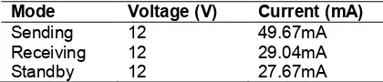
Table 5. Average measured total power consumption of the Sensor network module
Mode Voltage (V) Current (mA)
Sending 12 49.67mA
Receiving 12 29.04mA
Standby 12 27.67mA
It is important to state that the above measured average power consumption includes power consumed by all circuit components for both modules.
Working with the average values in Tables 5 and 6, the power supply requirement for both modules can easily be estimated. From Table 5, the sensor network module draws average current (49.67 mA) at 12V when sending data to the central sensor and security module. This helps to estimate the power rating for the power supply requirement for this module.
From = , ( ) = 49.67 × 12 ;
= 0.596
Therefore, the sensor network module requires an average of ~0.6 Watt power supply to run efficiently, which can be supplied using a solar rechargeable battery. Also as shown in Table 6 above, the central sensor and security module draws maximum current (116.3mA) at 12V while sending information to any of the sensor network module. This helps to estimate the power rating for components that make up the power supply unit.
From = , ( ) = 116.3 × 12 ; =
1.4
Table 6. Average measured total power consumption of the Central sensor and
security module
Mode Voltage (V) Current (mA)
Sending 12 116.3 mA
Receiving 12 95.7 mA
Standby 12 94.33 mA
Therefore, the central wireless sensor and security system module requires a 1.4 Watt power supply unit to run efficiently.
Power consumption of the central wireless sensor and security system module
Power consumption when sending data = 1.4W Power consumption when receiving data = 1.15W
Power consumption when idle = 1.13W
Power consumption of the sensor network module
Power consumption when sending data = 0.6W Power consumption when receiving data = 0.35W
Power consumption when idle = 0.33W
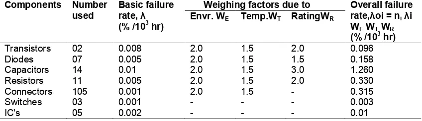
The reliability of the Sensor Network module design is calculated with reference to Table 7 as,
λT = ∑ λoi = 1.834 % /103 hr λT= 0.0183 /10
3 hr
R = e –λt = e –( 0.0183 x 0.001 x 8760) = e –( 0.161) = 0.851 = 85.1 %
The reliability [26,27] of the Sensor network module for a year of continuous operation is calculated below using data on Table 7.
While the reliability of the Central wireless Network module is,
from λT = ∑ λoi = 2.172 % /103 hr λT= 0.0217 /10
3 hr
R = e –λt = e –( 0.0217 x 0.001 x 8760) = e –( 0.1903) = 0.827 = 82.7 %
The reliability result is for a worst case situation, in which the Sensors network module and Central wireless module is under continuous
operation through-out the year round. It must be noted that the capacitors and resistors used in the system design contributes over 68% of the overall failure rate in both designs. Thus, if these are well rated, the reliability increases considerably. Also, if the connectors are well routed on the PCB to reduce damage, the reliability of the system can increase to about 97.5%, while the compact design with few components attached to the modules for proper operation improves the solidity of the system.This compares favorably with the Chinese product designs whose reliability assessment ranges between 50 and 70% for cost benefits [26,27].
The total harmonic distortion [THD] for the system response was calculated as 2.37%, while the measured THD with the use of a distortion analyzer is between 1.29% and 3.63% at a separated distance of 500 m between the sensor network module and the central wireless security system. The signal noise was calculated as 1.79dB, while the measured signal noise was 1.52dB and 2.34dB. The signal strength is about 72% of the maximum derivable of -42.7dBm from the system propagation. while the efficiency is calculated to be 96.7% with ease of maintenance due to few components used.
The cost of procurement and installation of a typical CCTV system in Nigeria is at an average of $3,500.00 while the cost of the developed system is valued at less than $1450.00., and this price shows an improvement and affordability without losing the quality of information required.
Figs. 7a and 7b Output from display when at least one switch in the PIR sensor group is activated [15]
Table 7. Failure rate of Basic circuit components for Sensor network module design
Components Number Used
Basic failure rate, λ (% /103 hr)
Weighing factors due to Overall failure
rate, λoi = ni λi
WE WT WR
(% /103 hr)
Envr. WE Temp.WT Rating.WR
Transistors 02 0.008 2.0 1.5 2.0 0.096
Diodes 07 0.005 2.0 1.5 1.5 0.158
Capacitors 10 0.01 2.0 1.5 3.0 0.9
Resistors 12 0.005 2.0 1.5 2.0 0.360
Connectors 100 0.001 2.0 1.5 - 0.3
Switches 02 0.001 - - - 0.002
IC's 06 0.002 - - - 0.012
Sensors 06 0.001 - - - 0.006
Fig. 8. Output waveform from the alarm circuit
Table 8. Failure rate of Basic circuit components for the central wireless network module design
Components Number used
Basic failure rate, λ (% /103 hr)
Weighing factors due to Overall failure
rate,λoi = ni λi
WE WT WR
(% /103 hr)
Envr. WE Temp.WT RatingWR
Transistors 02 0.008 2.0 1.5 2.0 0.096
Diodes 07 0.005 2.0 1.5 1.5 0.158
Capacitors 14 0.01 2.0 1.5 3.0 1.260
Resistors 11 0.005 2.0 1.5 2.0 0.330
Connectors 105 0.001 2.0 1.5 - 0.315
Switches 03 0.001 - - - 0.003
IC's 05 0.002 - - - 0.01
5. CONCLUSION
The design and simulation of the central wireless security system were carried out and the expected result was achieved. The sensor network module detected changes in state of sensors attached to it through a set of OR gates
a message describing such event is sent through the wireless network to the central security system for prompt action. A security alarm is triggered by the central security system to inform a connected user about such event for prompt action. The sensor network module is powered with 3.3V and 12V dc power derived from a simple ac-to-dc power designed, with 600mW power requirement, while the Central Security System is powered with 12V dc power with calculated 1.4W power requirement. The sensors network modules connect to the Central Security System at 72% of full signal strength of -42.7dB at a distance of less than 500metres with Omni-directional antenna used.
The design development was implemented at a cost of less than $1450.00 compared to an average of $3500.00 for CCTV installation which makes the development much more affordable to many households to protect their homes. Also, the power requirement is far less than what is required for a CCTV system, and the development can easily be powered using solar cells for year round continuous operation. The wireless Sensor module can be expanded for larger premises within the 500m threshold, to communicate with the Central wireless module with little additional cost, while the compact design with few components used improves the solidity of the system.
COMPETING INTERESTS
Authors have declared that no competing interests exist.
REFERENCES
1. Fagbohun OO, Oni OA. Studies on Security devices application in crime prevention and policing. American Journal of Engineering Research, India. 2016; 5(12):58-69.
2. Dempsey JS. Retail Security and Loss Prevention, in: Introduction to Private Security. Cengage Learning; 2010.
3. Barry P, Barry W. Crime free housing. Butterworth Architecture, Arnold publishers inc; 1991.
4. Duncan R. Revolution in home security. IEE communication Engineering magazine. 2003:36-42
5. Theraja BL, Theraja AK. A Textbook of Electrical Technology. 23rd revised ed. 2005:2599-2634.
6. Electronic Sensors, Microsoft ® Encarta ®; 2009.
7. Omoniyi OO, Fagbohun OO. Studies on electromechanical foam material (EFOAM) as a potential sensor and actuator. Journal of Electrical and Electronic Engineering (JEEE). 2014;9(2) ver. V:21-27. ANED-DDL 12.1676/iosr-jeee-E09252127. DOI:10.9790/1676-09252127
8. Fagbohun OO. Improving the policing system in Nigeria: Using electronic policing. Journal of Engineering and Applied Sciences. 2007;2(7):1223-1228. 9. Zulhani Razin. Water quality monitoring
system using ZigBee based wireless sensor network. International Journal of Engineering and Technology IJET. 2014; 9(10):24-28.
10. Chae MJ, Kim JR, Ctwoho MY. Bridge condition monitoring system using wireless network (CDMA and zigbee). 23rd International Symposium on Automation and Robotics in Construction ISARC 2006, Tokyo, Japan; 2006.
11. ZigBee,
https://en.m.wikipedia.org/wiki/ZigBee 12. The zigbee Alliance website; 2009.
Available: http//www.zigbee.org/
13. Tocci RC. Digital systems. Prentice Hall; 2015.
14. Batho ES. Electronic design principles. 1st edition, Prentice Hall inc, New Jersey; 1992.
15. Digital circuits and Boolean truth tables, Microsoft ® Encarta ®, © 1993-2008 Microsoft Corporation; 2009.
16. ATMEL 8-BIT Microcontroller with 4/8/16/32KBytes in-system programmable flash datasheet.pdf. visited on 2017-08-12
17. Sangmi Shim, Seungwoo Park,
Seunghong Hong. Parking management
system using ZigBee. IJCSNS
International Journal of Computer Science and Network Security. 2006:6(9B).
18. Vergari F, Auteri V, Corsi C, Lamberti CA. Zigbee-based ECG Transmission for low solution in home care service delivery. Mediterranean Journal of Pacing and Electrophysiology - Special Issue. Article Preview; 2009.
Available:http://www.mespe.net/en/newsel em/
20. Arduino.
Available:https://en.m.wikipedia.org/wiki/Ar duino
( Access Date 2017-06-18)
21. Fagbohun OO.Coding design for
information transfer in a de-centralised electronic policing system. Global Journal of Engineering and Technology. 2011; 4(2):193-198.
22. Fagbohun OO. Development of a low cost frequency shift keying signal transmitter for digital signal processing. IOSR Journal of
Electronics and Communication
Engineering (IOSR-JECE). 2014;9(2): Issue 5 ver. 1:36-43.
DOI: 10.9790/1676-09512635.
23. Fagbohun OO. Development of a receiver circuit for medium frequency shift keying signals. IOSR Journal of Electrical and
Electronic Engineering (IOSR-JEEE). 2014;9(2) ver. V:28-35; Aned dll 12.1676/iosr-jeee-F09252835;
DOI: 10.9790/1676-09252835
24. Fagbohun OO, Edeko FO. Development of a one touch information relay system for distress calls: Digital circuit design. International Journal of Engineering. 2010; 4(4):579-584.
25. Fred H, Paul L. Microprocessor fundamentals. Pitman Education Limited, second edition; 1992.
26. Dummer GW, Winton RC. An elementary guide to reliability. 8th edition, Pergamon press, U.K.; 1967.
27. Oroge CO. Fundamentals of reliability and testing methods. 2nd Edition, Sooji Press Ltd.; 1991.
© 2018 Fagbohun and Fagbohun; This is an Open Access article distributed under the terms of the Creative Commons Attribution License (http://creativecommons.org/licenses/by/4.0), which permits unrestricted use, distribution, and reproduction in any medium, provided the original work is properly cited.
Peer-review history:
![Fig. 1a. Block diagram of the sensor network module to be designed [9]](https://thumb-us.123doks.com/thumbv2/123dok_us/8411671.1691023/5.612.108.506.419.686/fig-a-block-diagram-sensor-network-module-designed.webp)
![Fig. 2a. Activity flowchart diagram of the sensor network module [22,23]](https://thumb-us.123doks.com/thumbv2/123dok_us/8411671.1691023/7.612.143.471.212.464/fig-a-activity-flowchart-diagram-sensor-network-module.webp)
![Fig. 3. Schematic design of the wireless sensor module [13,15]](https://thumb-us.123doks.com/thumbv2/123dok_us/8411671.1691023/8.612.103.514.95.212/fig-schematic-design-wireless-sensor-module.webp)
![Fig. 4. Control and display unit for a central wireless security system [11,16,19]](https://thumb-us.123doks.com/thumbv2/123dok_us/8411671.1691023/9.612.115.506.108.692/fig-control-display-unit-central-wireless-security.webp)