Research Article
GNSSim:
An
Open
Source
GNSS/GPS
Framework
for
Unmanned
Aerial
Vehicular
Network
Simulation
Farha
Jahan
1,
Ahmad
Y.
Javaid
1,∗,
Weiqing
Sun
2,
Mansoor
Alam
11EECSDepartment,CollegeofEngineering,TheUniversityofToledo,Toledo,Ohio,USA
2ETDepartment,CollegeofEngineering,TheUniversityofToledo,Toledo,Ohio,USA
Abstract
Unmanned systems are of greatimportance in accomplishing tasks where human lives are atrisk. These systems are being deployed in tasks that are time-consuming, expensive or inconclusive if accomplished by human intervention. Design, development and testing of such vehicles using actual hardware could be quite costly and dangerous. Anotherissue is the limited outdoor usage permitted by Federal Aviation Administrationregulations, which makes outdoortesting difficult. Anoptimal solutionto thisproblem is tohaveasimulationenvironment wheredifferentoperationalscenarios,newlydevelopedmodels,etc.,can be studied. In this paper, we propose GNSSim, a Global Navigation Satellite System (GNSS) simulation framework.WedemonstrateitseffectivenessbyintegratingitwithUAVSim.Thisallowsuserstoexperiment easilybyadjustingdifferentsatelliteaswellasUAVparameters.Relatedtestsandevidenceofthecorrectness oftheimplementationarepresented.
Receivedon 13 April 2015;acceptedon 17 July 2015;publishedon 11 August 2015 Keywords: Vehicular Network, Satellite Navigation, Network Simulation
Copyright © 2015 Ahmad Y. Javaid et al., licensed to EAI. This is an open access article distributed under the terms
of the Creative Commons Attribution license (http://creativecommons.org/licenses/by/3.0/), which permitsunlimiteduse,distributionandreproductioninanymediumsolongastheoriginalworkisproperlycited. doi:10.4108/eai.11-8-2015.150091
1. Introduction
The remarkable growth in mobility and location-aware vehicles, as well as related applications, have led to increased use of such vehicles in almost every domain. Mostly operations in these areas pose a risk to human lives due to the unknown nature of the terrain, weather or other environmental factors. One of the most popular class of vehicles under this category is unmanned aerial vehicles, UAVs. These systems can be sent to distant or inaccessible planetary bodies for research (e.g., Philae
aircraft landed on a comet after a 10 year journey [1]) or
to detect and monitor real-time catastrophes like
earth-quake [2] and forest fires [3]. UAVs have found their
use in applications like agricultural chemical
deploy-ment [4], ecological surveys [5], natural event
moni-toring (Hurricane Hunter [6]), disaster management [7]
and humanitarian response (e.g., damage assessment, search and rescue operations, dropping relief supplies
in case of emergency [8]), 3-D Mapping and
photogram-metry [9], wildlife protection [10], etc.
∗
Correspondingauthor. E-mail: [email protected]
In early 2015, commercial UAVs were authorized to fly in US National Airspace (NAS) by Federal Aviation Administration (FAA). More than 7500 UAVs are expected to be seen in the air by 2020 due to this authorization, compared to the number being negligible
in 2014 [6]. Even today, FAA does not require people
to obtain license for small and mini-UAVs which are used for recreational purpose while limiting the usage up to a height of 400 ft. and away from airport and
air traffic [11]. These new laws and availability of
low-cost mini-UAVs and Do-It-Yourself (DIY) drones have promoted individual use as well as research in industries and academia. Constructing a drone is nowadays possible within as less as $300 by purchasing
separate parts from online stores [12]. Clearly, incorrect
or failure in accurate navigation may lead to dangerous and life-threatening accidents for medium-sized UAVs and thus, necessitates prior testing of a model in a simulation environment.
1.1. Role of Navigation
A navigation module is one of the most critical components of location and mobility-aware vehicles
1
EAI Endorsed Transactions
on
Mobile
Communications
and
Applications
EAI Endorsed Transactions on Mobile Communications and Applications
Figure 1. Role of navigation in UAV operations
and has become a necessary part of any vehicular simulation. Navigation serves as the operator’s eyes and ears in any unknown terrain. Be it an aircraft, a ship, a car or any other vehicle, navigation allows the vehicle to move around in an area accurately, avoiding any mishaps. In military operations, accurate navigation serves as a necessary intelligence in the mission area and ensures the safety of all involved. Aircraft, Gunship
and UAV operators already suffer from stress and
performance pressure due to the responsibility of human lives. Accurate and reliable navigation data reduces mission related anxiety, impact on their mental health and optimal operational performance of the
team [13]. Figure1depicts the role of navigation in such
critical UAV operations.
1.2. Problem Statement
This paper focuses on developing a GNSS simulation framework for the location and mobility-aware vehic-ular networks. Such a framework should allow any nav-igation system simulation including GPS, GLONASS, Galileo, and BeiDou. Simultaneously, a need was felt for an accurate and inexpensive GNSS simulation frame-work for unmanned vehicular netframe-works in academia. Previously proposed UAVSim addressed this concern partially as it lacked any navigation related simulation
capability [14]. Therefore, an independent GNSS/GPS
simulation framework was designed, which can be used in UAVSim as well as with other OMNeT++ based vehicular network simulations. In this paper, we are using GPS to demonstrate the navigation functionality. Therefore, all the discussion from here onwards may refer to GPS and GNSS interchangeably.
The primary component of such a module is its GPS unit that allows it to be location and mobility
aware. It also helps the UAV during different preset
navigation modes, such as position hold,
return-to-home, autonomous flight and object avoidance [15].
Depending on the area in which the UAV is deployed, GPS can be used to link data to its spatial position
(geo-referencing). GPS signals are typically very weak, less than 100W and are transmitted over a range
of 20−25,000 kilometers. This makes them fall
below the noise floor spectrum when they reach the
earth’s surface [16]. These signals are vulnerable to
failure, disruption and interference from unintentional or deliberate sources. The increased dependency of UAVs on GPS signals for localization, navigation and time-synchronization has made it a focus area for adversaries. This shift of adversary focus led to the discovery of its vulnerabilities to attacks like Spoofing and Jamming. Accurate modeling of UAV along with GPS and related navigational aspects is very critical for accurate vehicular network simulations.
To sum up, the following technical contributions have been made in this paper:
• An OMNeT++ framework incorporating real GPS satellite and weather data have been developed. It enables users to capture both the real characteristics of unmanned aerial vehicle mobility and address the complexity of aerial pathways.
• Both the Satellite-end GPS signal transmitter and vehicle-end GPS signal receiver have been imple-mented using standard trilateration equations. This receiver can be used in OMNeT++ for sim-ulation as a component of any mobile node.
• Extensive simulation studies have been per-formed to reveal the achievable performance of the simulation framework using a wide range of important parameters. Most importantly, we have investigated the impact of the various mobility models, the angle of motion, and speed. These studies prove the correctness of the proposed framework.
The rest of the paper comprises of five sections. We discuss related work in the area of GNSS simulation
framework development in Section 2 while Section 3
gives a brief overview of GPS and presents our
implementation of GNSS/GPS. Section 4 presents the
design, architecture and operation of the framework when combined with the UAV simulation testbed
UAVSim. Section5presents the simulation analysis and
results, and the paper is finally concluded in Section6.
2. Related Work
This section discusses the work that has been done in the area of GPS simulation for UAV Networks. Much work is deemed out of scope as they primarily focus on modeling of a single UAV in a closed lab or an open but controlled environment to improve the system performance, flight range, and usability. A lack of close-to-real simulation of a UAV
2
EAI
for InnovationEuropean AllianceEAI Endorsed Transactions on Mobile Communications and Applications
Table 1. Comparison of software based GPS simulators
Simulator GNSS Type Language Visualization Vehicular Network
Simulation Capability
GSSF Galileo, GPS C++ Yes No
SNACS Supports All C++/MATLAB Yes No
Open-SESSAME Supports All C++ Yes No
network (UAVNet) including UAVs, Satellites, and Ground Control Stations (GCS) was also noticed. An ideal testbed should allow inter and intra-component communication, and intra-component level behavioral analysis. We present a classification of these existing simulators based on the presence of GPS implementation as well as few independent GPS simulators.
2.1. UAV Simulators with GPS
A visual 3D flight simulation software based on
MATLAB and Simulink was an early attempt towards simulating a UAV, which used the navigation module
of FlightGear [17]. FlightGear provides a generic
GPS support where GPS receivers are yet to be
implemented [18]. Another Java-based project called
UAV Playground used FlightGear to receive GPS data
and implemented GPS tracking in Google Earth [19]. In
industry, the aeronautical division of IDS Corporation has implemented an unmanned aerial vehicle simulator
Hero UAVSim [20] composed of ground control stations
(GCS) [21], a UAV Simulator and a sensor payload
simulator [22]. The UAV Simulator has GPS-based
auto tracking capability and GPS outage mitigation measures while GCS has an integrated GPS receiver to determine its actual position.
2.2. Independent Hardware based GPS Simulators
Several hardware based GNSS simulators are avail-able for purchase through various manufacturers. In academia, researchers tend to incline towards open source solutions rather than expensive hardware based solutions. Nonetheless, a few popular ones have been discussed here. The LabSat simulator is a low-cost hard-ware based simulator and provides selection options
such as GPS, GLONASS, Beidou, and Galileo [23]. It
generates genuine navigation signals that can be stored,
replayed and used in different applications. Spirent
implements several similar hardware, e.g., GSS9000 multi-frequency, multi-GNSS RF constellation simula-tor for professional, controllable and repeatable testing
in the lab [24]. A GPS simulator by National
Instru-ments (NI) can produce GPS signals of up to 12
satel-lites and is aimed at testing GPS receivers [25]. Many
other simulators such as IFEN Inc. NavX-NCS Profes-sional/Essential, CAST Navigation SGX GPS Satellite
Simulator, AeroFlex Portable GPS/Galileo/SBAS Posi-tional Simulator GPSG-1000, etc., also simulate GPS
and GNSS but differ with respect to the range of
sig-nals produced and constellation implemented. All these devices are quite expensive and could not be considered as low-cost for a UAV simulation testbed developed in an academic setup.
2.3. Independent Software based GPS Simulators
Very few researchers have developed pure software-based GNSS simulators. There are few simulators avail-able for purchase too, but we our focus lies in open source solutions. GSSF, SNACS, and Open-SESSAME
were the top-three in this category. Table 1 gives a
brief comparative analysis of these three software based simulators. Galileo System Simulation Facility (GSSF) is
focused on the Galileo navigation system [26].
Imple-mented in C++, it provides a simulation for longer time periods and large geographical area coverage. It pro-vides raw Galileo and GPS signal generation, express mode simulation, and good functionality to analyze and visualize data. Another work, Satellite Navigation Radio Channel Signal Simulator (SNACS), is a single
GNSS satellite signal generator [27]. It is open source
and implemented in C++ with parallel processing. Its radio channel input and simulation results can be analyzed in MATLAB. Open-SESSAME (Open-Source, Extensible Spacecraft Simulation and Modeling Envi-ronment framework) is another popular simulator that provides dynamics simulation for spacecrafts for
devel-oping hardware as well as testing flight algorithms [28].
Based on C++, it provides attitude and orbit modeling along with features of orbit simulation, space envi-ronment assessment or control algorithm validation. One of the biggest limitations of all these simulators is the unavailability of any interfacing with any network simulation software to enable vehicular network simu-lation.
2.4. OS3
As mentioned earlier, most hardware based simulators were found to be quite expensive while software based simulators were not compatible with any vehicular network simulation platform. A candidate solution to this problem was found as OMNET++ based OS3 (Open
Source Satellite Simulator) [29, 30]. OS3 provides a
3
EAI
for InnovationEuropean AllianceEAI Endorsed Transactions on Mobile Communications and Applications
Figure 2. Global Positioning System (GPS) requires a minimum of 24 satellites [31]
generic satellite constellation that seamlessly integrates real satellite tracks and weather data to simulate
different conditions along with good visualization. The
limitation here was the unavailability of any satellite communication for the implementation of a working GNSS. Nonetheless, the implementation of a highly accurate and stable satellite model and movement in OS3 provided a good base for the development of GNSSim. Being platform independent, OS3 can be deployed easily on any system.
3. GNSS/GPS Overview
In this section, we will briefly introduce GNSS and how the positioning works in a GPS receiver.
3.1. GNSS/GPS Basics
A system of satellites that provides autonomous geo-spatial positioning with global coverage is termed as Global Navigation Satellite System (GNSS). Currently, the GPS and the Russian GLONASS are the only GNSS supporting global coverage. Other prospective
GNSSs are BeiDou of China and Galileo of Europe [27].
Any GNSS has three operational segments - the space segment, the ground/control segment, and the user segment.
A working global navigation solution is easily possible with 24 satellites located in six orbital planes
as shown in Figure 2 [31]. To improve the accuracy
of GPS, its space segment was designed to have 31 satellites. These satellites complete two revolutions around the earth in one day. A GPS satellite sends
Figure 3. 3D trilatateration [33]
two ranging codes: C/A, used for public usage, and Precision code, used by the military. The signal consists of GPS data and time, ephemeris data and the almanac. The ground/control segment consists of ground stations that track the GPS satellites, monitor their transmissions, analyze their performance, and send commands and control information to the constellation. The ground network consists of one master control station, one alternate master station, 12 command and control antennas, and 16 monitoring sites. The end-user antenna and GPS receiver make the user segment that receives and calculates the position, velocity and time based on the data from the GPS Satellite. The receiver has to acquire and maintain the lock on four satellites to get its accurate position in the 3Dspace [32].
3.2. Position Calculation
A GPS receiver calculates its position by using a
method called Trilateration which is shown in Figure3.
Many trilateration algorithms have been proposed to determine location accurately. The most widely accepted mathematical expressions to calculate a
position in 2Dand 3Dare discussed here [33].
3D multi-lateration uses the following standard
equations.
2·(x2−x1)·x+ 2·(y2−y1)·y+ 2·(z2−z1)·z=α
2·(x3−x1)·x+ 2·(y3−y)·y+ 2·(z3−z)·z=β
2·(x4−x1)·x+ 2·(y4−y)·y+ 2·(z3−z)·z=γ
where
α = (d12−d2
2)−(x21−x22)−(y12−y22)−(z21−z22)
β= (d12−d2
3)−(x21−x32)−(y12−y32)−(z21−z23)
4
EAI
for InnovationEuropean AllianceEAI Endorsed Transactions on Mobile Communications and Applications
γ= (d12−d2
3)−(x21−x23)−(y12−y32)−(z21−z32)
By solving the following matrix based equations, we get the value of (x, y, z) in 3Dspace.
x=f(d1, d2, d3, d4) =
α 2Y12 2Z12 β 2Y13 2Z13 γ 2Y14 2Z14
2X12 2Y12 2Z12
2X13 2Y13 2Z13
2X14 2Y14 2Z14
y=g(d1, d2, d3, d4) =
2X12 α 2Z12
2X13 β 2Z13
2X14 γ 2Z14
2X12 2Y12 2Z12
2X13 2Y13 2Z13
2X14 2Y14 2Z14
y=g(d1, d2, d3, d4) =
2X12 2Y12 α
2X13 2Y13 β
2X14 2Y14 γ
2X12 2Y12 2Z12
2X13 2Y13 2Z13
2X14 2Y14 2Z14
where Xij, Yij and Zij are referred to as (xi−xj), (yi −yj) and (zi−zj), respectively.
Similarly, in 2D, which is a trilateration method, the
position of an object can be determined by solving the following equations:
(x−x1)2+ (y−y1)2= (d1)2
(x−x2)2+ (y−y2)2= (d2)2
(x−x3)2+ (y−y3)2= (d3)2
The equations are converted to linear equations by subtraction and substitution:
2·(x2−x1)·x+ 2·(y2−y1)·y=α
2·(x3−x1)·x+ 2·(y3−y1)·y =β
where
α= (d12−d2
2)−(x21−x22)−(y12−y22)
β= (d12−d2
3)−(x21−x23)−(y12−y32)
Finally, the position (x, y) is obtained by solving the following matrix operations:
x=f(d1, d2, d3) =
α 2Y12 β 2Y13
2X12 2Y12
2X13 2Y13
y =g(d1, d2, d3) =
2X12 α
2X13 β
2X12 2Y12
2X13 2Y13
whereXijandYijare referred to as (xi −xj) and (yi−yj), respectively.
4. GNSS Framework Design
A very common and major limitation of most satellite
simulation software, except OS3, is the difficulty in
their integration with other network simulators like OMNET++, NS-2, etc. To fulfill our primary aim of developing a GNSS framework for vehicular network simulation, we chose OS3 due to its base simulation engine of OMNeT++ and the availability of satellite mobility models. OS3 implements a generic satellite constellation and uses a TLE (Two-Line Element) format file for fetching initial positions of various satellites being used for simulation. Depending upon which Navigation System TLE file we use, that specific navigation system can be simulated. As an example, we can use a TLE file containing data of 31 GPS satellites to simulate GPS while we can use a TLE file containing data of 30 Galileo satellites to simulate the Galileo Navigation System. It provides an accurate satellite movement simulation with live weather data,
high-resolution altitude data, different visualization
options, etc. The comparison of these existing satellite
frameworks has been done in [29].
Some major limitations of OS3, and how they were addressed during the implementation phase, have been discussed in the next subsection.
4.1. OS3 Limitations and Solutions
• No Satellite Communication: We designed various
satellite communication modules in our frame-work to make satellites capable of transmitting signals and establish communication links.
• No GNSS: GPS or any other navigation technique
was not implemented in OS3. We implemented the GNSS using basic trilateration equations
mentioned in the section3.2.
• No Vehicular Simulation: OMNeT++ allows any
discrete event simulation within its framework and thus allows vehicular simulation as long as proper models are designed. Therefore, we used our previously developed UAV simulation testbed
UAVSim [14] to demonstrate the proposed GNSS
framework’s capability in vehicular network simulation.
5
EAI
for InnovationEuropean AllianceEAI Endorsed Transactions on Mobile Communications and Applications
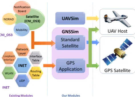
Figure 4. Architectural design of the GNSSim framework
4.2. GNSS Framework Modules
GNSSim framework comprises of several modules, as
depicted in Figure4. The GNSSim modules are shown
in red in this figure. UAVSim modules are not shown in this figure and more about these modules could
be found in [14]. UAVSim allows us to create the
UAV Network along with enabling option of choosing from several UAV models. The GNSSim modules are discussed here.
Satellite Model Library. Satellite model library has the standard satellite model that inherits its basic features from the satellite model defined in CNI_OS3. The GPS functionality has been added to the satellite model through the development of a broadcasting application that sends position information to the
receivers through radio signals of the L1 frequency
range as per the standard GPS implementation. The GPS/SATNAV implementation has been described in detail in section3.
Satellite Network Module. Similar to the UAV network module of UAVSim, this module defines the network stack of satellites. It defines the communication protocol, transmission power, access points, etc. This
Figure 5. GNSS/GPS implementation
module imports several basic packages from INET for satellite communication while the satellite mobility packages are imported from OS3.
Navigation Module. The navigation module has the receiver end GPS application that enables the hosts to receive satellite navigation signals carrying position
6
EAI
for InnovationEuropean Alliance on Mobile Communications and Applications EAI Endorsed TransactionsFigure 6. World map used for GPS simulations
information. The information from four or more satellites is required to calculate the position of
the UAV using multi-lateration in the 3D space. In
our implementation, we have used trilateration for localization. Therefore, a minimum of three satellites are required.
4.3. Implementation
Figure 5 explains the implementation of the GPS
system. The space segment constitutes of GPS satellites while the user segment in this scenario would be UAV hosts. The base satellite model with the NORAD (North American Aerospace Defense Command) module, mobility model, and notification board has been defined in CNI_OS3. The base satellite model has been enhanced to the standard satellite model that now includes the communication protocol stack.
The GPS Application has been designed from scratch over a connectionless broadcasting protocol. This application is required in the satellites to create and broadcast packets. On the UAV host, this application acts as a GPS receiver in the navigation module. It receives the packets from the satellites and process received data for localization.
The communication between UAVs and satellites or any GPS receiver is unidirectional. Satellites broadcast signals without waiting for any acknowledgment. That is why a connectionless broadcasting protocol was used to implement GPS. The packets contain the satellite index, X coordinates and Y coordinates of the satellite sending the packet, in map meters, and the distance
with each host. For the first time when a UAV receives the packet, it locks on that particular satellite. After
obtaining a lock on three different satellites, the UAV
calculates its position. Further, it calculates its position whenever it receives three more packets from these
satellites using the 2Dtrilateration equations as defined
in section3.2. If the UAV does not receive any packets
for 10s, the lock is released, and a new satellite to lock
on to is searched. Such a situation is termed as Locate-the-sky.
The implementation of GPS is very basic and an approximation of the real GPS. We have implemented the localization using trilateration, considering the map meters as the position of the satellites and hosts. The scaling of the earth to the map has been done as follows. Considering that the radius of the earth as 6371 km, the circumference of the earth will be
2πr= 2×3.14×6371
If we imagine opening the globe vertically, the circumference will give the length of the map while the width of the map will be half the circumference. The map dimensions are defined as
1080×2160
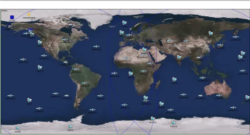
The Figure 6 shows the world map in the simulation
environment. So horizontally, each pixel on the map corresponds to
2×3.14×6371×103
2160 = 18.5km
7
EAI
for InnovationEuropean AllianceEAI Endorsed Transactions on Mobile Communications and Applications
Figure 7. Satellite ground track [34]
or vertically,
3.14×6371×103
1080 = 18.5km
Therefore,
1m= 1
(18.5×10³)m(onmap)
Different UAV models available today have different
speeds depending upon its design and usage. The Arcangel-1 has a speed of 150 km/h while USAF mission UAVs like Patroller can fly at a speed of 241 km/h. Taking an approximate speed of 250 km/h of a UAV or 69.5 m/s, the speed of the satellite on the simulation map will be
69.5/(18.5×103) = 0.0037m/s(onmap).
This speed value is set in the simulation configuration
fileomnetpp.ini.
The user-defined parameters, such as the number of satellites and UAV hosts, can be defined in the same configuration file. The simulation world map shown in
the Figure6shows 30 satellites in orbit. The motion of
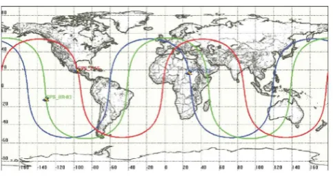
the satellites in their orbits around the planet appears
as a sine wave on a planar map, as shown in Figure7.
For illustration, 20 hosts are shown on the map. The number of hosts can be varied for each simulation. The OS3 module defines the web-service related data, weather control data, and a calculation module that calculates the distance, attenuation, and other channel characteristics. We have also implemented the DGPS stations in the form of access points, which function as a ground-based central transmitter and receiver of satellite radio signals. The blue circles show the range of each access point. If a host is outside the range, it will not receive any packets. The range of access points needs to cover the whole area of the map so that the host is always in the line-of-sight of one or more satellites. A
minimum of four access points is sufficient to cover the
whole area with the given range.
Table 2. Default satellite parameters
Parameter Value
Simulation Time Limit 600s
Mobility Type SatSGP4Mobility
Transmitter Power 500W
Packet Interval 0.5s
Burst Duration 10s
Sleep Duration 0s
Position Update Interval 1s
Table 3. Default host parameters
Parameter Value
Mobility Type Linear Mobility
Transmitter Power 10W
Speed 0.0037 m/s
Burst Duration 10s
Sleep Duration 0s
Position Update Interval 1s
Limitations and Assumptions. Some of the assumptions and limitations of GNSSim implementation are listed here:
• Although GNSSim implements both the space segment and user segment; the control segment is not implemented.
• Only the primary functionality of GPS, position calculation of the UAV is implemented at the receiver end.
• Use of ephemeris and almanac data for calculation of the position is implemented approximately. The satellites sends its position information relative to the UAV in the packet as a parameter rather than calculating the distance using the speed of light and the time of transmission.
5. Simulation Analysis and Results
In this section, we demonstrate the simulation results based on the implementation of the navigation module in UAV hosts. The results are analyzed to demonstrate the correctness of the implementation. The various scenarios and variation in parameters have been analyzed with respect to the localization. The below tables show the default values of the satellites and the host during our simulations.
The background image of the map of the earth used is the default one used in OS3. Other background images can easily be used by changing it in the configuration file. Using the testbed, we analyzed how the UAV performed with the navigation module implemented. The following simulation experiments show the accuracy of UAV localization with respect
8
EAI
for InnovationEuropean AllianceEAI Endorsed Transactions on Mobile Communications and Applications
Figure 8. Variation in localization with simulation time
Figure 9. Variation in localization with number of hosts
to variation in different parameters, using the average
error as a indication of correctness. The average error is obtained by calculating the distance between actual UAV position and the calculated position, and taking an average over the whole simulation.
5.1. Average Localization versus Simulation Time and
Number of Host
Although the localization count is not the same in every run, with the increase in the simulation time, the
average localization increases, as shown in Figure8. It
should be noted that the average localization decreases with the increase in the number of hosts, as shown clearly in Figure9.
5.2. Average Localization versus Satellite Lock
Obtaining a lock is important to get a very accurate position. Satellites broadcast signals all the time.
Figure 10. Localization curve without lock implemented on satellites during localization
Figure 11. Localization curve with lock implemented on satellites during localization
Also, there can be more than three satellites (2D
implementation) in line-of-sight but at different
distances from the host. The calculated distance is
prone to error, but the effort should be to have a
minimal error. If every calculation of the localization uses data from different sets of satellites, it will lead to a larger variation between the calculated position and
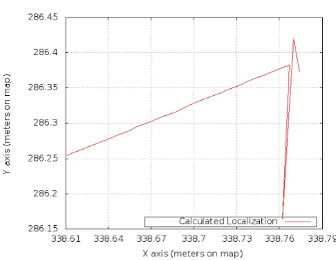
the original position. Figure10 shows the variation in
localization when no lock on the satellites is in place. The variation between the calculated localization curve and the actual curve was so large that they could not be plotted together.
When the lock on the satellites is implemented, the
variation in error reduces to a minimum of 0.001.
The calculated position almost overlaps the original
position. Figure 11 shows the localization curve to be
9
EAI
for InnovationEuropean Alliance on Mobile Communications and Applications EAI Endorsed TransactionsFigure 12. Graph of circular mobility
Figure 13. Graph of complete trajectory of circular mobility
in sync with the original path through the lock on the satellites.
5.3. Implementation of Circular Mobility Model
The simulation runs as expected in different mobility
models. For Linear Mobility, the UAV travels a linear path as shown in the above figures. Most of our simulation analysis is performed with Linear Mobility.
Figure12shows the circular path of the UAV host when
the mobility model is changed to Circle Mobility. The user needs to define the center of the path and the radius. To get the complete circular trajectory as in
Figure13, the simulation was run for 1000 simulation
seconds. For this particular case, the center was taken as (x,y) = (561m, 432m) in map meters and radius as 1
meter which corresponds to 18.5 km in the real world.
These mobility models are already defined in the INET
Figure 14. Distance traveled with speed
Figure 15. Average error variation with change in speed of host
module. Other mobility models can also be used for simulation.
5.4. Average Localization versus Speed
As the speed of the UAV host increases, as expected, the
distance covered by the UAV increases. Figure14shows
the distance traveled by the UAV with different speeds.
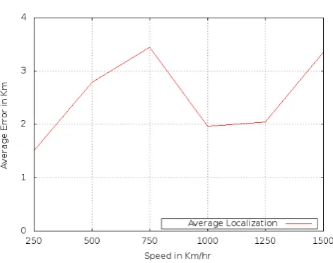
The green curve shows the distance traveled when the speed is 250 km/h, and the red curve shows the distance traveled when the speed is 500 km/h keeping the simulation time as 400 seconds. With the increase in speed, the average localization error increases, as shown
in Figure 15. The default value of the speed is 0.0037
mps, i.e., 250 km/h. The speed could also be defined in the configuration file as a Gaussian function with a normal distribution truncated to non-negative values and a standard deviation of 0.005.
10
EAI
for InnovationEuropean AllianceEAI Endorsed Transactions on Mobile Communications and Applications
Figure 16. Path of host at different start angles
Figure 17. Average error variation with change in start angle
5.5. Variation in Angle of Linear Motion
The default value of the angle of linear motion is random and uniformly distributed between 0 to 360
degrees. Figure 16 shows the calculated path of the
host at different angles. As we can see from the figure,
the host follows a correct path using its calculated
localization data. Figure 17 shows the average error
at different angles. The average error increases as we
move from its linear axis and becomes minimum again
at 90 degrees. Figure 18 shows the variation in the
localization error with the simulation time for three
different angles. The maximum localization error is less
than 1% for all evaluated cases. As we can see from the
figure 18, the number of errors in localization varied
with change in the starting angle of the UAV host.
Figure 18. Localization error variation with simulation time
Figure 19. Localization error variation with change in sleep duration
5.6. Sleep Duration versus Localization
GPS based navigation can offer relatively consistent
accuracy if sufficient GPS signals can be tracked during
the entire UAV mission [35]. Due to its low power range,
intentional or unintentional interference can cause UAVs to lose the signals. The GPS signal outage can cause a significant deviation in the navigation solutions.
11
EAI
for InnovationEuropean AllianceEAI Endorsed Transactions on Mobile Communications and Applications
Figure 20. Average localization error variation with change in sleep duration
To represent such a scenario where UAVs lose the signal because of interference from television signals, mobile signals, ultra wideband communications or when traveling around high buildings and trees, our testbed has a parameter called ’sleep duration’, which corresponds to such a GPS signal outage. The parameter can be assigned to both the satellites and the host. In case of satellites, during the specified sleep duration, they would be inactive and would not broadcast any packets while the hosts would reject packets even if a satellite is sending them. The default sleep duration has been kept at 0s for the satellites as well as the host assuming that there is no outage, and the UAV receives signals during entire simulation.
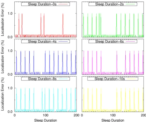
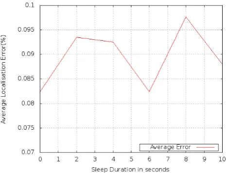
The Figures19and20show the effect of a change of
sleep duration on the localization error. The simulation has been mapped from 0s - 10s of sleep duration with an interval of 2s for 200 localization values. These figures clearly show that the maximum error reaches about a maximum of 1% for all evaluated cases. The average localization error is almost negligible which shows the accuracy of the localization algorithm.
6. Conclusion and Future Work
In this work, we proposed a generic GNSS simulation framework called GNSSim. We also utilized this framework to simulate UAV networks using an existing UAV simulation testbed called UAVSim, which was incomplete without a navigation module. To fully implement the GPS navigation, we needed the GPS satellite constellation and a GPS signal receiver in UAV. Various simulation experiments
were performed by varying different parameters in
GNSSim, and the results were analyzed and discussed to prove the correctness of the implementation.
Incorporation in another OMNeT++ based simulation testbed was aimed at proving its utility as a generic GNSS framework for any vehicular simulation in OMNeT++. Future work may include improvement upon a few limitations of UAVSim and GPS/SATNAV implementation. Another important future work might
include the implementation of different GPS related
attacks and their mitigation techniques, such as GPS spoofing and GPS Jamming.
References
[1] M. Kramer, European Spacecraft Lands on Comet in Historic Space Feat, http : / / www . space . com / 27740-rosetta-comet-landing-success . html, online; Last accessed: 18-July-2015 (November 2014). [2] Humanitarian UAVs Fly in China After Earthquake
(updated), http : / / irevolution . net / 2014 / 08 / 25 / humanitarian-uav-china-earthquake/, online; Last accessed: 18-July-2015 (August 2014).
[3] B. Gabert, NASA testing UAV to detect fires,http:// fireaviation.com/tag/uav/, online; Last accessed: 18-July-2015 (October 2014).
[4] R. Austin, Unmanned Air Systems UAV Design, Development and Deployment, fisrt Edition, Wiley, John Wiley & Sons Ltd, The Atrium, Southern Gate, Chichester, West Sussex, PO19 8SQ, United Kingdom, 2010.
[5] K. Anderson, K. Gaston, Lightweight unmanned aerial vehicles will revolutionize spatial ecology, Frontiers in Ecology and the Environment 11 (3) (2013) 138–146. doi:10.2307/23470549.
[6] B. Handwerk, 5 Surprising Drone Uses (Besides Amazon Delivery),http://tinyurl.com/nhfla3r, online; Last accessed: 18-July-2015 (December 2013).
[7] H. Kelly, Drones: The future of disaster response, http : / / whatsnext . blogs . cnn . com / 2013 / 05 / 23 / drones-the-future-of-disaster-response/, online; Last accessed: 18-July-2015 (May 2013).
[8] D. Gilman, Unmanned Aerial Vehicles in Humanitarian Response, online; Last accessed: 18-July-2015 (June 2014).
[9] F. Remondino, L. Barazzetti, F. Nex, M. Scaioni, D. Sarazzi, UAV Photogrammetry for Mapping and 3D Modeling - Current Status and FuturevPerspectives (September 2011).
[10] G. Green, Rhino-saving drones: How UAVs are being used for wildlife conservation, http://tinyurl.com/ ok67zac, online; Last accessed: 18-July-2015 (May 2014). [11] FAA, Unmanned Aircraft Systems, online; Last accessed:
18-July-2015 (November 2014).
[12] kborgen, Scratch build your own quad-copter!, http : / / www . instructables . com / id / Scratch-build-your-own-quad-copter / step2 / Materials/, online; Last accessed: 18-July-2015 (August 2013).
[13] J. A. Ouma, W. L. Chappelle, A. Salinas, Facets of occupational burnout among US Air Force active duty and National Guard/reserve MQ-1 predator and MQ-9 reaper operators, Tech. rep., DTIC Document (2011).
12
EAI
for InnovationEuropean AllianceEAI Endorsed Transactions on Mobile Communications and Applications
[14] A. Y. Javaid, W. Sun, M. Alam, UAVSim: A simulation testbed for unmanned aerial vehicle network cyber security analysis, in: 2013 IEEE Globecom Workshops (GC Wkshps), 2013, pp. 1432–1436. doi : 10 . 1109 / GLOCOMW.2013.6825196.
[15] A. Amato, Is GPS Connectivity Important for Your Drone, http : / / dronelife . com / 2014 / 10 / 24 / drone-need-gps-connection/, online; Last accessed: 18-July-2015 (October 2014).
[16] M. Thomas, et al., Global Navigation Space Systems: reliance and vulnerabilities (2011).
[17] Y. Qiang, X. Bin, Z. Yao, Y. Yanping, L. Haotao, Z. Wei, Visual simulation system for quadrotor unmanned aerial vehicles, in: 2011 30th Chinese Control Conference (CCC), 2011, pp. 454–459.
[18] FlightGear Wiki, Global Positioning System, http : / / wiki . flightgear . org / Global _ Positioning _ System, online; Last accessed: 18-July-2015 (December 2013). [19] Jarontec, uavplayground: An approach to Unmanned
Aerial Vehicles (UAV) with Java and the Processing Development Environment, https : / / code . google . com/p/uavplayground/, online; Last accessed: 18-July-2015 (August 2010).
[20] IDS Corporation Aeronautical Division, Hero UAVSim Unmanned Aerial Vehicle Simulator, https : / / www . idscorporation . com / images / aeronautical / homepage / BRO _ AERO _ HEROSIM . pdf, online; Last accessed: 18-July-2015.
[21] IDS Corporation Aeronautical Division, Hero UAVSim Unmanned Aerial Vehicle Simulator, https : / / www . idscorporation . com / images / aeronautical / homepage / BRO _ AERO _ HEROGCS . pdf, online; Last accessed: 18-July-2015.
[22] IDS Corporation Aeronautical Division, Hero UAVSim Unmanned Aerial Vehicle Simulator, https : / / www . idscorporation . com / images / aeronautical / homepage / BRO _ AERO _ HEROUAV . pdf, online; Last accessed: 18-July-2015.
[23] LabSat, LabSat GPS Simulator,http://www.labsat.co. uk/index.php/en/, online; Last accessed: 18-July-2015. [24] Spirent, GPS Simulation Simulate GPS signals for
professional, controllable and testing in the lab,http: / / www . spirent . com / Positioning-and-Navigation / GPS_Simulation, online; Last accessed: 18-July-2015. [25] National Instruments, NI GPS Simulator PXI RF Test
System for GPS Receiver Test, http://sine.ni.com/
nips/cds/view/p/lang/en/nid/206805, online; Last accessed: 18-July-2015.
[26] F. Zimmermann, T. Haak, C. Hill, Galileo system simulation facility (2004).
[27] F. M. Schubert, R. Prieto-Cerdeira, P. Robertson, B. H. Fleury, SNACS–The Satellite Navigation Radio Channel Signal Simulator, Proc ION GNSS. Institute of Navigation, Savannah, GA (2009) 1982–1988.
[28] A. J. Turner, An open-source, extensible spacecraft simulation and modeling environment framework, Ph.D. thesis, Virginia Polytechnic Institute and State University (2003).
[29] I. C. Wietfeld, The Open Source Satellite Simulator, http : / / www-os3 . kn . e-technik . tu-dortmund . de / index.php, online; Last accessed: 18-July-2015 (2014). [30] B. Niehoefer, S. Šubik, C. Wietfeld, The CNI Open
Source Satellite Simulator Based on OMNeT++, in: Proceedings of the 6th International ICST Conference on Simulation Tools and Techniques, SimuTools ’13, ICST (Institute for Computer Sciences, Social-Informatics and Telecommunications Engineering), ICST, Brussels, Belgium, Belgium, 2013, pp. 314–321.
URLhttp://dl.acm.org/citation.cfm?id=2512734. 2512779
[31] E. Ayrapetian, Electronic Designs for Space: Radiation, http : / / www . nuvation . com / blog / electronic-design-services / electronic-designs-space, online; Last accessed: 18-July-2015 (November 2013).
[32] GPS.Gov, Systems: Space Segment, http://www.gps. gov/systems/gps/space/, [Online; Last accessed: 18-July-2015 (October 2014).
[33] H. Seo, H. Kim, Four Anchor Sensor Nodes Based Localization Algorithm over Three-Dimensional Space, Journal of information and communication convergence engineering 10 (4) (2012) 349–358.
[34] What-when-how, A Few Standard Orbits (Orbital Mechanics Interlude) (Remote Sensing), http : / / tinyurl.com/obvb8qz, online; Last accessed: 18-July-2015.
[35] J. Wang, M. Garratt, A. Lambert, J. J. Wang, S. Han, D. Sinclair, Integration of GPS/INS/vision sensors to navigate unmanned aerial vehicles, IAPRSSIS 37 (B1) (2008) 963–9.
13
EAI
for InnovationEuropean AllianceEAI Endorsed Transactions on Mobile Communications and Applications


![Figure 2. Global Positioning System (GPS) requires a minimumof 24 satellites [31]](https://thumb-us.123doks.com/thumbv2/123dok_us/8424192.1695294/4.595.311.545.89.281/figure-global-positioning-system-gps-requires-minimumof-satellites.webp)