Volume-7 Issue-2
International Journal of Intellectual Advancements
and Research in Engineering Computations
Investigation on material properties of 3D printer by using multijet
technology
S. Eswaran
1, J. Rajesh
2,R. Rajapandiyan
2,T. S. Rajesh
2,S. Surya
21
Assistant Professor,
2UG Students
Department of Mechanical Engineeing, Nandha Engineering College, Erode - 52.
TamilNadu. India.
ABSTRACT
With Additive Manufacturing (AM) abilities hastily increasing in commercial packages, there exists a need to quantify materials' mechanical residences to ensure reliable performance this is rob ust to versions in surroundings and construct orientation. even as prior research has examined method -parameter and environmental effects for am procedures which include extrusion, vat photo polymerization, and powder bed fusion, current comparable studies at the cloth jetting process is restrained. Specializing in polypropylene -like and elastomeric-like substances, the authors first represent the anisotropic residences of six special gradients constituted of blending the two substances in preset portions. Three build orientations had been used to fabricate components and examine tensile pressure, modulus of elasticity, and elongation at damage for each cloth. The authors additionally present results from a research of how getting older of elements in unique lighting conditions impacts cloth houses. The effects from these experiments provide a more advantageous knowledge of the material behaviors relating to material jetting method parameters and can tell cloth choice when manufacturing load-bearing parts.
Keywords:
3D printer, Multijet technology, Tensile, Flexural.INTRODUCTION
Additive Manufacturing (AM) is quickly evolving from a method for prototyping to a desired alternative for manufacturing qui t-use merchandise. due to the nature of a layer-by-layer fabrication procedure, customizable artefacts are plausible that shop fabric, time, and price compared to traditionally-manufactured components. The first form of creating layer by layer a 3D object using computer-aided design (CAD) became rapid prototyping, Advanced within the 1980’s for developing models and prototype components [1-3].
Technology
There are two types of technologies involved to create a specimen model.
1. 3D Printing
2. Polyjet Technology
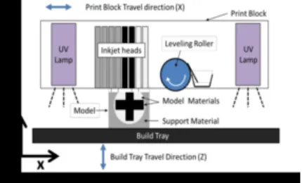
The paper characterizes the method, its variants and modifications; it also classifies the models and the modifications. In the PolyJet process, a print block consisting of the inkjet heads deposits the support or build materials in drop-by-drop deposition patterns, which are smoothed by a roller and cured by a UV lamp [4-7].
Fig 1. Representation of the PolyJet Printing Process
Polyjet Technology
Polyjet is a powerful technology that produces smooth, accurate parts, prototypes and tooling with microscopic layer resolution and accuracy 0.1mm.It can produce thin walls and complex geometries using the widest range of materials available with any technology [2].
Material Used
Vero white Vero Blue
Vero Clear
Form of Material: Liquid Photopolymer Curing Medium: Ultra violet Ray (Light) Types of Printing, Mode
1. High Quality (16 Microns) 2. High Speed (30 Microns) 3. Digital Materials (30 Microns)
Orientation
1. In-build plane part orientation(X-Y) 2. Out-build plane part orientation (Z)
Types of Finish
1. Glossy Finish 2. Matte Finish.
LITERATURE REVIEW
Rapid prototyping is a tool less manufacturing process; it has ability to manufacture a product/prototype directly from CAD models by allowing its geometric freedom (Hopkinson & Dickens 2003).
It can produce very complex structures and
cavities, when compared with
traditional/conventional manufacturing (Petzold, Zeilhofer and Kalender, 1999).
It is alternative production method for conventional moulding and machining technique (Hopkinson & Dickens 2003).
The technology has been adopted primarily in
major markets such as
automotive,aerospace,electronics and consumer electronics, medical devices, footwear.(Chua C.K., Leong K.F 2003)
The Production of parts using this technology can be applied in silicon moulding, investment casting.(A.Kesy & Kotlinski 2006).
3D PRINTING GENERAL
PRINCIPLES
Modeling
3D Process
3D process is a MIT-licensed process in which water-based liquid binder is supplied in a jet onto a starch-based powder to print the data from a CAD drawing. The powder particles4 ISRN Mechanical Engineering.
Rapid Prototyping
1. Material Jetting 2. Binder Jetting 3. Material Extrusion
4. Directed Energy Deposition 5. Sheet Lamination
6. Vat Photo polymerization 7. Powder bed fusion.
DESIGN CONCEPT
Design of each and every material should based on some standard dimensions. That standard dimensions are given by the testing society. For the tensile and flexural test, the dimensions are given by the ASTM (American Society for Testing Materials).
2D Model
2D Model has been created by using Solid Works as well as Auto CAD.
Specimen Types
1. Tensile Specimen 2. Flexural Specimen
Tensile Specimen
Standard: ASTM D638 for Tensile Specimen
Fig.2. Tensile Dog Bone Shape
Flexural Specimen
Standard: ASTM D790 for Flexural Specimen.
Specimen Designation
1. Tensile D638 2. Flexural D790
Printing Modes
High Quality 1. Matte Finish 2. Glossy Finish High Speed 1. Matte Finish 2. Glossy Finish
Digital
Autodesk (the manufacturer of AutoCAD) makes a product that is nearly identical to Solid works, called Inventor, which is a parametric program for design of solid parts and assemblies. Solid Works is a 3D mechanical CAD
(computer-aided design) program that runs on Microsoft Windows [8-12].
ANALYSIS
Derivation
High Quality: Matte Finish
Actual Length: 165mm
Actual Width: 19mm
Thickness: 3.2mm
Tensile Strength Result
Test Speed Tensile: 50mm/min
Flexural:12mm/min
Fig.4 Tensile Strength Result
High Speed: 30 Microns
Pre-load: 0.1MPaC.
C. Flexural strength result
Test Speed
Tensile: 50mm/min
Flexural: 12mm/min
Fig.5 Flexural Strength Result
Shore hardness
Fig.6 Shore Hardness
High Quality: 30 Microns
Pre-load: 0.1MPa.
CONCLUSION
Though the printer-produced resolution is sufficient for many applications, printing a slightly oversized version of the desired object in standard resolution and then removing material with a
higher-resolution subtractive process can achieve greater precision some printable polymers such as ABS, allow the surface finish to be smoothed and improved using 3D printer based on similar. Some additive manufacturing techniques are capable of using multiple materials in the course of constructing parts.
Material used : Vero white Gear type : Spur gear
Fig.7 Oil Pump Gear
These techniques are able to print in multiple colours and colour combinations simultaneously, and would not necessarily require painting. Some printing techniques require internal supports to be built for overhanging features during construction.
REFERENCES
[1]. Kaufui V. Wong and Aldo Hernandez “A Review of Additive Manufacturing,” Department of Mechanical and Aerospace Engineering, University of Miami, Coral Gables, FL 33146, USA, 2012.
[2]. Lindsey B. Bass, Nicholas A. Meisel, and Christopher B. Willams “Exploring variablity in material properties of multi material jetting papers,” Design, Research and Education for Additive Manufacturing Systems Laboratory Department of Mechanical Engineering, Virginia Tech.
[3]. “Development trends in additive manufacturing and 3D printing,”Engineering 2015, 1(1):85 -89 DOI 10. 15302/J-ENG-2015012.
[4]. Stanislaw Adamczak, Jerzy Bochnia, Bozena Kaczmarska, “An analysis of tensile test result to assess the innovation risk for an additive manufacturing technology,” Kielce University of Technology, Al. 1000 -lecia P. P. 7, 25-314 Kielce, Poland, Department of Manufacturing Engineering and Metrology (Department of Production Engineering).
[5]. Jochen Mueller “Tensile properties of inkjet 3D printed parts: Critical process parameters and effect analysis their efficient analysis,” Engineering Design and Computing Laboratory Departmet of Mechanical and Process Engineering, ETH Zurich, 8091 Zurich, Switzerland.
[6]. K.Pueble S.M.Gaytan, F.Medina, L.E. Murr*, and R.B. Wicker “Technology Exploitation of mechanical properties,” W.M. Keck Center for 3D Innovation University of Texas-EI Paso.
[7]. The Production of parts using this technology can be applied in silicon moulding, investment casting.(A.Kesy & Kotlinski 2006)
[8]. YAN Yongnian, LI Shengjie, ZHANG Renji, 0LIN Feng, WU Rendong, LU Qingping, XIONG Zhuo, WANG Xiaohong. “Rapid prototyping and manufacturing technology Principle representative technics, applications and development trends,” Key Laboratory for Advanced Materials Processing Technology of Ministry of Education, Department of Mechanical Engineering, Tsinghua University, Beijing 1 00084, China, June 2009.
[9]. Rapid prototyping is a tool less manufacturing process, it has ability to manufacture a product/prototype directly from CAD models by allowing its geometric freedom (Hopkinson & Dickens 2003).
[10]. It can produce very complex structures and cavities, when compared with traditional/conventional manufacturing (Petzold, Zeilhofer and Kalender, 1999).
[11]. It is alternative production method for conventional moulding and machining technique (Hopkinson & Dickens 2003).