Intelligent Trace and Evaluation for Parallel
Programming Based on Architectural Details
Jiaxin Li
School of Computer Science and Technology, Beijing Institute of Technology, Beijing, China Email: [email protected]
Feng Shi, Ning Deng, Qi Zuo, Zuo Wang, Mengxiao Liu
School of Computer Science and Technology, Beijing Institute of Technology, Beijing, China Email: {dunning2006, liu.mengxiao}@gmail.com, [email protected]
Abstract—As CMP became the main stream of processer
design, parallel programming is a new challenge for programmer. The execution of the same program may perform much different based on various multi-core architectures. Even the same multi-core processor combined with different mapping strategies are still with distinct performance. How could programmers figure out if their programs, which based on specific multi-processing architectures and mapping strategies, are efficient and even portable? In this paper, we propose Architecture-Based Trace and Evaluation (ABTE) and corresponding framework, which intelligent helps programmers to approximate the performance of their solutions without real running. ABTE mainly includes two parts: 1) the library of architecture models and algorithms; 2) the evaluate engine. We introduce the method of describing models of various architectures and their running algorithms. Based on the models, we propose a marked object trace method to help evaluate the parallel solutions, and use it in the evaluate engine. We explain ABTE by a case study, and the evaluation shows that ABTE can help programmers find the better solution to a parallel application without real running.
Index Terms—parallel computing model, performance
evaluation, TriBA
I. INTRODUCTION
Parallel programming is hard for programmers who are familiar with serial programming. They must transform their serial thinking style into parallel, and learn more about architectural details. Without these transforming, the solutions of parallel application may waste available computing resources and even get poor performance.
Programmers are familiar with several software parallel computation models, such as PRAM[13], BSP [12] , and LogP[14] etc. Using the parallel computation models can design and describe their algorithms with possible omissions to some hardware details. Shared memory and distributed memory with massage passing are two basic concepts to build these models that widely used in parallel programming. And as a particular case, stream computing is also an important technology in
special areas like image processing and science computing.
A combination of selections from software parallel computatiom models, algorithms and hardware architectures are called solutions to an parallel application. Which solution performs better is important for programmers. If the performance can be approximated without real running the solution, programmers would need to only focus on the solutions with better match to their requirement. The features of programming and solutions should be explored for better estimating.
SWARM [15] is a parallel programming framework for multicore processors. It is a descendant of a SMP node library component to develop efficient multicore algorithms. Because of their application is limited to SMP (Symmetrical Multi-Processor) computing, they offer a multicore model considering three primary issues affect performance: number of processing cores, caching and memory bandwidth and synchronization. Streamware [17] offers a framework and a runtime environment to make it possible to use the stream programming model to efficiently run on general-purpose processors. This software system uses a fixed software model and various hardware models.
In this paper, we propose Architecture-Based Trace and Evaluation (ABTE), which can estimate the performance of a solution before running. It includes two parts: 1) the library of architecture models and algorithms; 2) the intelligent evaluate engine. In our framework that implementing ABTE, we target on not only general purpose processors, but also stream processors. Our hardware model address on the ability of reconfiguring fine granularity memory blocks, processing elements, and interconnections, thus the hardware model is scalable and flexible. We also offer a software model library including popular parallel programming models.
OpenMP [6] is a better way for processors to interact with each other in a shared memory model.
Many tools and solutions are mainly implemented in two ways: library-based and new language-based. MPI and OpenMP are all add a parallel library to existing languages. The new language-based way, such as DSVMs [16] or stream languages like Stream-C/Kernel-C [8] and StreaMIT [7], offers a new language to manipulate on specific hardware, and can map the application directly to the architecture or API.
We integrate a programming interface in our framework, and allow add-in several kinds of parallel compilers. This makes our framework becoming language-unrelated. Programmers can focus on the optimization of their applications, and use languages they familiar with.
In section 2, we introduce the method of describing models of hardware architectures and algorithms. The software model and algorithms involved in our method is explained in section 3. And the ABTE framework is also introduced in this section. A method of marking object for tracing and evaluation is proposed in section 4, and a simple application is used as an example to explain the course of ABTE works. In section 5, we use ABTE to evaluate several solutions to the application, and compare the results with experimental results. We find that though ABTE can’t work as accurate as runtime evaluation, it can help programmers find the correct trend of which solution is better.
II. PARALLEL COMPUTING MODEL
In ABTE, hardware architecture is an important factor involved in evaluation. We extract key features from architectures and describe them in an object-oriented pattern to form corresponding Parallel Computing Models (PCMs). A PCM is set up based on static information of a specific parallel hardware, which supports several running modes. These running mode based on the hardware features are called PCM algorithms. For example, the IBM Power5 [10] architecture can be described into Power5 PCM, which includes its features of processing elements, memory and the interconnections between them. The Power5 PCM algorithms are running mode according to the feature of Power5, such as Power5 SMT algorithm which describes that how the thread could be scheduled into CPU and running.
In this section, we propose the method of building PCM and PCM algorithm, and explain them by modeling TriBA[3], which is a novel multi-core architecture. A. Model description
PCM are composed of processing elements (PE), memory system (MS), and interconnections (IC) between them. In logical view, every feature is the composite of many components, the types of which may be same or different. In the implementation, we don’t really generate so many objects, but define position and range information of forming a block, and save a pointer refers
to one object saved in a component pool to represent the component type to form the block.
(a)
(b)
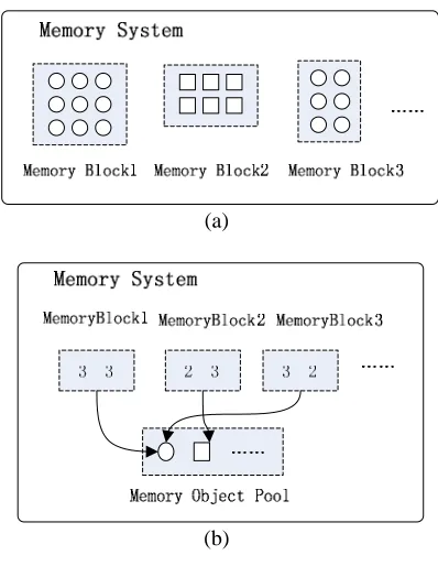
Figure 1. The example of component pool
In Figure 1 we take memory system as an example. We suppose that a memory system is composed of several memory blocks with two different types, which are represented as cycles and squares respectively. Figure 1(a) shows the logical view. If we don’t use component pool to optimize it, 3×3+2×3+3×2=21 memory element objects would be generated. Figure 1(b) shows the implementation with component pool. In this way, only 2 memory element objects are generated.
Figure 2. Class graph of PCM pattern
every ProcElement-MemBlock pair shows the privilege of access. And the computing_pattern parameter defines how the PCM organize its instructions and data streams, which is one kind of SIMD, MIMD or the others. A MemSystem is a set of MemBlocks, which is similar to Processor that is composed of a number of ProcElements. In this way, a MS or PE can be easily configured whether the component in them are homomorphic (like RAW X[2]X)
or heteromorphic (like a processing system in which Imagine X[1]X as a co-processor of a general purpose
processor). The parameters without explicit type are actually representing corresponding component pools.
IC is implemented in a different way. It is a weighted graph called ICG:
1 2 1 2 1 2 1 2
1 1 1 2 2 2
( , )
{ , ,... , ,...[ , ,... , ...]}
{( , , ), ( , , ),...}, i, i , 1, 2...
ICG V E
V P P M M B B S S
E X Y w X Y w X Y V i
= =
= ∈ =
Elements of vertexes set V could be processors (P), memory blocks (M), switches of on-chip network(S) or buses (B). If there is a direct path between two vertexes i and j, then an edge (i, j, w) will be included in the edge set E, and w is the weight of this edge. This weight represents the transfer latency between two vertexes. The latency’s order of magnitude is set from the performance of real hardware. For example, a processor P has a private on-chip cache A, and it can also access off-chip memory B, then edges (P, A, W1) and (P, B, W2) are included in the ICG, in which if W1 is 3, then W2 may be 30 or even larger. This helps in evaluation and can inform users to revise their design for better use of cache and reduce the accesses to remote memory. Each vertex in ICG can also be a smaller ICG. In this case, we can express different granularity of the system. The more detail granularity is, the more accurate the evaluation would be.
B. PCM algorithm description
PCM algorithm determines when and how to process or move data to complete the function of an application. It is represented as a set of objects and several relationships. As shown in XTable 1X, the objects are with
two types: Operation and Data, each of which has several subtypes. Data objects as a formatted communication unit (Message objects) or a block of data (Data block objects) are passive that only can be manipulated by Operation objects. While Operation objects are active to process data (Function objects), resize data (Split/Merge objects), or direct objects from one place to another (Schedule objects).
TABLE I.
ABBREVIATION OF OBJECTS IN PCM ALGORITHM DESCRIPTION
Objects Abbr. Objects Abbr.
Operation O Data D
Function Of Message Dm
Split/Merge Od/Om Data block Dd Schedule Os
Objects may be composed of sub-objects, and for each time that object is divided into sub-objects, the algorithm is described in a more detail way. As the granularity of objects is fine enough, the algorithm would be translated into executable codes.
In parallel programming, two basic relationships are required: Parallel (represents with ||) and Dependent (represents with
f
). Let A and B are two objects. A||B means that A and B can be execute at the same time; Af
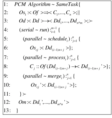
B means that B only can be executed after the execution of A.For representing in a more compact way, we defined three kinds of code blocks: Pipeline block, Serial block and Parallel block. Based on the representations upon, PCM algorithms can be easily built and stored as templates in a PCM algorithm library. Here we take one PCM algorithm as an example (see XFigure 2X).
In Figure 3. , The SameTask algorithm describes that tasks (which are function objects) with the same function are distributed into each PE, and the data is divided into blocks to parallel processed by the PEs. In the representation A~B, B is the name of function A. In the 2-3 lines Os1 schedule a function object to n computing elements, and in the mean time Od split Dd into m*n smaller data objects. The objects in the “<>” after “:” means the operands of the object before “:”, and that after “→” or “⇒” represents the result of the operation or the destination of the schedule. The 4th to 11th lines shows a serial block. A serial block defined as: :n1{ }
i i Serial = O means that object O1 to On runs in a sequence, which can also be expressed as Serial:{ ;O O1 2;...;On;} that with the
same meaning ofO1fO2f f... On;. The parallel and
pipeline block are descript similarly.
1 1 1 * 1 1 1 ( 1)
1: ~ {
2: : ,..., ;||
3: : ,..., ;
4: ( ~ ) : {
5: ( ~ ) : {
6: :
n n m m i n i j
cj i n j
PCM Algorithm SameTask
Os Of C C
Od Dd Dd Dd
serial run parallel schedule Os Dd − = = − +
< >⇒< > < >→< >
<
f
1
( 1) ( 1)
1
( 1)
1
};
7: ( ~ ) : {
8: :: ( ) ' };
9: ( ~ ) : {
10: ' : ' };
11: }
12: : ',..
n i j
j i n j i n j
n i j
cj i n j
parallel process
C Of Dd Dd
parallel merge Os Dd Om Dd = − + − + = − + > →< > < > < f * ., '
13 : }
m n Dd >
Figure 3. SameTask algorithm description
C. TriBA based parallel computing model
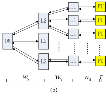
TriBA [3] is a multi-core architecture with a special triplet-based interconnection, different scales of which are shown in XFigure 4X.
(a)
(b)
Figure 4. Hierarchical interconnections of computing cores and hierarchy memory system in TriBA [3]
Every node in the figure is called a cell, the typical configuration of which consists of three function units: processing unit (ProcUnit), data unit (DataUnit), and interface unit (InterUnit). A L1 cache permits private access of each ProcUnit. Every three cells share access a L2 cache. If cache misses, each of the 9 cells can access to an off-chip memory.
The course of configuring 9-cell TriBA pattern in ABTE is described as follows:
The basic computing element of TriBA is ProcUnit in a cell, so only one instance of ProcElement with parameters initialed as ProcUnit is generated and stored in processor pool. Similarly, three kinds of memories are used in TriBA: 16KB on-chip L1 private cache, 64KB on-chip L2 group shared cache, and 512MB off-chip memory. L1 cache and L2 cache are built by a special 4-port SRAM, while off-chip memory is a DRAM. So there are two kinds of objects of SByte_4P and DByte stored in the memory pool to build SRAM or DRAM respectively. The objects of different MemoryBlock are initialed in
XTable 2X.
TABLE II. MEMORYBLOCKS
MemoryBlocks row column mtype
L1 cache 512 32 SByte_4P
L2 cache 2048 32 SByte_4P
Off-chip memory 64000000 8 DByte
The Interconnection graph is initialed as Figure 5.
9
1 2 3
1 9
1 2 3
1 9
4 5 6
1
( , );
{ , , , 1 } { 2 , 2 , 2 , };
{( , , ), ( , , ), ( , , )};
{( , 1 , ), ( , 1 , ), ( , 1 , )};
{( 1 , 2
TriBA TriBA TriBA
TriBA i i i i
i
TriBA i i i i i i
i
i i i i i i
i
i
ICG V E
V PU IU DU L C and L C L C L C OM
E PU IU w PU DU w IU DU w
and PU L C w DU L C w IU L C w
and L C L C
=
=
=
=
=
=
U
U
U
3
1 7 8
1
6 9
2 7 3 7
4 7
2
3 3 1 9 3 3 2 9 3 1 3 2 9
i=0
2 4 9 3 7 9 6 8 9
, ), ( 2 , , )};
{( 1 , 2 , )}; {( 1 , 2 , )};
{( , , ), ( , , ), ( , , )};
{( , , ), ( , , ), ( , , )}.
i i
i i
i i
i i i i i i
w L C OM w
and L C L C w and L C L C w
and IU IU w IU IU w IU IU w
and IU IU w IU IU w IU IU w
=
= =
+ + + +
U
U
U
U
Figure 5. The TriBA Interconnection Graph
In ICGTriBA, different kinds of edges are of different
weights, which are approximated by the real architecture of TriBA. The PCM of TriBA is configured and store into the PCM library. Programmers will be able to choose the exist model in this library.
III. PARALLEL SOLVING MODEL AND ABTE FRAMEWORK
A. Parallel solving model
As a PCM describes the parallel hardware, a Parallel Solving Model (PSM) shows the feature of parallel software design. The algorithms based on the mechanism of specific PSM are called PSM algorithms. The course of solving a parallel problem is actually a course of mapping, from software to hardware, from PSM to PCM, and from PSM algorithm to PCM algorithm. Without proper mapping, parallel applications would not run efficiently.
Two software models are widely used in parallel programming: message passing and shared memory. Stream processing is also a parallel model playing an important part in image and science computing. We set these three models as basic PSMs. Each of them could gain better performance in the architecture with features proper for the model running.
The message passing model assumes that the underlying hardware is a collection of PEs, each with its own local memory, and an interconnection network supporting message passing between PEs. So the latency of communications plays a dominated role in static evaluation.
The underlying hardware of shared memory model is assumed to be a collection of PEs, each with access to the same shared memory. PEs can interact and synchronize with each other through shared variables.
The underlying hardware of stream processing model is a stream processor which equipped with a fast, efficient, proprietary bus or crossbar switches, and a large cache in which stream data is stored to be transferred to external memory in bulks.
PSM algorithms are actually the parallel algorithms that people always call. They may base on one or more PSMs. For example, when solving Gaussian elimination problem X[4]X, we can use row-oriented algorithm or
column-oriented algorithm, which are based on message passing PSM.
PSM and PSM algorithms are represented in software aspect, which are actually the common view that programmers think about parallel programming. Hardware features are not easy for programmers to understand or even to consider its effects in the course of coding. The architecture-based trace and evaluation we proposed here aims to help them figure out how the performance would be when a PSM combined with specific hardware before programming on it.
B. ABTE Framework
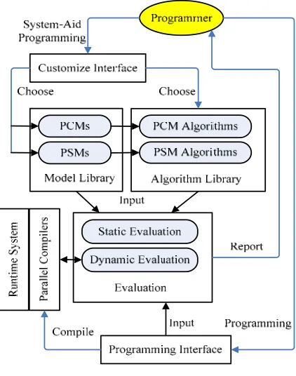
Figure 6. Organization of ABTE
ABTE framework can motivate the greatest creativity of human designers and achieving optimized way to solve a given problem. The framework captures the feature of solving parallel problems. It is organized as an object-oriented system, in which every part can be seemed as an object. Thus the framework is scalable and portable. User can simply add or change function components to construct a more suitable framework. As shown in Figure 6, it is composed of following parts:
1) Customize interface. It is an interface offered to programmers if they choose system-aid programming,
then help them choose models and algorithms that fit for their applications.
2) Model library and algorithm library. Model library keeps PCMs and PSMs, which have been expressed in corresponding model description patterns, the definition and examples will be introduced in next section. The libraries can be automatically refreshed by several times of running of the system.
3) Evaluation engine. It is used for evaluate the input design, and return the evaluation result to programmers to optimize their design. According to the design environment, two kinds of evaluations can be used. Static engine analyzes the source code combining the hardware/software models and algorithms chosen by programmers. The key part of static engine is an object-extract analyzer, which will be explained following part of the paper. Dynamic engine runs the key part of the code, which can be specified by programmers, on demanded hardware architecture to obtain more accurate evaluations. However, dynamic engine only can evaluate application based on the PCMs match the hardware architecture running the ABTE framework. The selected key parts of application may not reveal the true performance. But if run the whole application, some huge problem set may cost too much time and computing resources. The static way makes it easier to primarily learn the performance of design on several sets of hardware, thus programmers can choose comparatively better method to implement their applications without too much effort.
4) Programming interface. There are two ways for programmers to design on ABTE framework. The first way is coding based on models and algorithms offered by the framework. The second way is to directly input program components to the evaluation engine, and figure out if the program is suitable for running on specific hardware architecture. Programming interface is used in both of the ways. Inputting a configure file for the application, the interface helps programmers to insert necessary marks or control primitives to the program.
5) Parallel compilers and runtime system. These two parts are necessary for mapping our programmed applications to hardware architectures. The parallel compilers, which is reconfigured based on exist compilers, help to translate programs into executable codes based on the models and algorithms that has been chosen. The real mapping operations are be realized in runtime systems.
IV. MARKED OBJECT TRACE
Applications that need to be solved in parallel are always composed of a number of tasks or require dealing with huge set of data. Most of them are actually repeating a series of operations for many times. If the latency of iteration can be computed, the performance of the whole application would be easy to estimate.
instruction, data is still need to be transferred from on register to another. The “computing” time may only is a small part of the total latency of the program. The most time of running a program is spent for transferring. Based on this thought, we propose a method to trace the latency of transferring to evaluate the performance of parallel program.
In the field of molecular biology, luminescent protein
X[11]X is widely used for observing intracellular
localization of proteins. In our method, we also use “luminescent objects” to observe and trace the running of parallel program. Imagine that a set of objects are marked with green and are involved into the running program. During the life time of the objects, the transferring path they passed by and the computing elements they have emerged in will all be colored with green. The green trace would be a record for iteration. We can also use multiple colors of objects to mark multiple kinds of function components that we want to learn. By tracing these marks, we can estimate performance of the whole application. The course of ABTE is described as follows, in which (P) and (E) respectively means that the step is completed by programmers or evaluation engine:
1) Choosing the PSM, PCM and corresponding algorithms, making necessary changes and settings to form a solution of the application. (P)
2) Marking objects in the solution. (P)
3) Analyzing the solution and generating mappings between PSM and PCM, PSM algorithm and PCM algorithm. (E)
4) Generating trace path of marked objects, and computing the latency of each trace path according to the weights defined in ICG. (E)
5) Computing the total latency according to the mapping information and generating evaluation results. (E)
6) If the results are not satisfying, return to 1). (P). Here we explain the ABTE method by using TriBA to solve a simple parallel application. The problem is to do the same arithmetic operations on a set of data. For each number A in a set with 90000 members, we will do the following arithmetic operations and save the result R back: R=A A( + −4) 5.
For the first step, programmer chooses to use shared memory PSM, and a PSM algorithm to generate multiple same tasks to compute concurrently. And naturally the TriBA PCM and the SameTask PCM algorithm defined in XFigure 3X are chosen. The parameters m and n in
SameTask are set to 9 and 10000 respectively. In the second step, the object Dd1 is marked.
8
w
w
7w
4 T(a)
8
w
w
7w
4 T(b)
Figure 7. Traces in TriBA example
From the third step, the evaluation engine begins to work. It maps computing task into 9 Of objects, and the shared memory is mapped to hierarchy memory system of TriBA. The fourth step is to trace the path of marked object Dd1: Dd1 stored in off-chip memory are transferred into a L2 cache, and then be transferred into a L1 cache. Processors access L1 cache to fetch Dd1, and computing, and then send the result Dd1‘ back. When all the numbers finished computing, L1 caches transfer numbers to L2, and L2 transfer to off-chip memory. Dd1‘ is transformed from Dd1, so the mark (color) is also taken by Dd1‘.
XFigure 7 X(a) explains this trace. According to the ICGTriBA,
the latency of Dd1 transferring is 2(w8+w7+w4), and the latency of computing is T. The latency of transferring and computing are active time of Dd1. There is also some time that Dd1 is not active, such as staying at memory waiting for others are transferred. The static time is marked in the trace to process in the next step.
When computing the total latency of this application, the engine evaluates the parallelism of Dd1-like objects.
XFigure 7 X(b) shows the traces of them. The structure of
special four-port memory in TriBA can support four concurrent transfers. According to the PCM algorithm and parameters of TriBA architecture, we can compute Latency of each phase using the formula, in which BW(M) means the band wide of M, D is the data block that transferred, and w is the weight defined in ICG:
1 2 1 2
1 2
( )
min( ( ), ( ))
M M M M
Length of D
Latency D w
BW M BW M
− −
⎡ ⎤
=⎢ ⎥×
⎢ ⎥
The result is returned to the programmer, who can choose to change for other solution or setting detail of the model to gain more accurate results.
V. EVALUATION
In this section, we still take the application in section 4 as an example to evaluate ABTE in two aspects: usability and accuracy. We have already used ABTE to evaluate the solution with shared memory PSM and TriBA PCM. Now we will consider the evaluation of other solutions and compare them to find a better one.
We configure four solutions, which are different combinations of two PCMs and two PSMs. The PCMs are 9-core TriBA and a 9-core CMP with on-chip network as 2D-mesh, in which every core has a 16KB L1 cache and all of them have a distributed and shared L2 cache (192KB in total) and a 512MB off-chip memory. These two PCMs seemingly have similar computing ability. The PSMs we choose message passing and shared memory.
TABLE III.
TRANSFER LATENCY IN DIFFERENT PHASES
PCM OM-L2 L2-L1 L1-PU C-C
TriBA 65 20 3 17
2D-mesh 75-55 10 2 17
The algorithm with message passing is to distribute one kind of operation (addition, subtraction and multiplication) to one computing element, and we finish computing an R will take 3 cores. The result computed by one core will transferred to another core as a message to do the next computation. The operations of the three cores can form a pipeline.
In XTable 3X, the main transfer latency of the two PCM
is listed. OM means the off-chip memory and C-C means the latency of communication between two directly connected cores. The computing time of multiplication is 6, while addition and subtraction are 3.
0 0.2 0.4 0.6 0.8 1 1.2 1.4 1.6 1.8
Latency
(m
illi
o
n
)
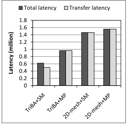
Total latency Transfer latency
Figure 8. Latency of four solutions by ABTE
XFigure 8X shows total latency and transfer latency of the
four solutions. SM and MP are short for shared memory and message passing. From these results, programmers will know that the better solution to this application would be TriBA PCM combined with shared memory PSM. Except for the TriBA+SM solution, the latency of transferring is almost equal to the total latency. That is because the transferring occupied most of the running time, and some of the transferring time is overlapped with the computing time. The solutions with 2D-mesh PCM need more time than that with TriBA PCM. That is because TriBA contains multi-port memories, which allow for high throughput of data.
0.00 0.20 0.40 0.60 0.80 1.00 1.20 1.40 1.60 1.80 2.00
Latency
(m
illi
o
n
)
ABTE Exp.
Figure 9. Compare ABTE evaluation with experimental results
A better solution for the application may have the feature of high speed transferring and memory, which are exactly the feature of stream processors. As ABTE is based on models that even the hardware architecture is not available, it can also evaluate the supposed solution. We assume that the stream processor is formed like the Imagine stream processor in X[1]X, only change the number
of ALU Cluster to 9, and the size of memory system is similar to TriBA. The PSM is chosen as stream model, in which three kinds of operations are configured as 3 kernels mapping onto the clusters. The latency of this solution is shown in XFigure 9X, which is much less than
the others.
TABLE IV.
ERRORS OF ABTE EVALUATION WITH EXPERIMENTAL RESULTS
PCM Error TriBA-SM 0.2212 TriBA-MP 0.0614 2D-mesh-SM - 0.0370 2D-mesh-MP 0.1600 Imagine-Stream -0.1063
We implement these five solutions based on CMP-SIM
X[9]X, which is a cycle-accurate multi-core simulation
environment. In XTable 4X,. ”Error” is computed by:
(
-)
/Though the errors between the two groups are not so small, the trend of which solution is accurate, the purpose of the framework is satisfied. Programmers can choose the better solution to an application depend on the ABTE results.
VI. CONCLUSIONS AND FUTURE WORK
ABTE method helps to evaluate a solution of a parallel problem before real running it. With the compare of performance between various solutions, programmer can find the better one to implement without waste time on solutions that can’t reach the requirement.
This method is supposed to be supported by the model description of varies architectures and algorithms, an evaluate engine and an interface to programmers. Now we have defined PCMs and PCM algorithms to describe several architectures and their running mode. With the help of these models and algorithms, we have implemented marked object trace method in the evaluate engine to evaluate solutions selected by programmers.
The user interface is not very convenient that we have to choose and set the solutions by changing the options in the configure file. In future works, we will build a graphical interface that can help programmers express their designs only by dragging several graphs and input some numbers. As the evaluate engine now only focus on evaluating the latency of the solution, in the next step we will extract other features such as usage of memory and occupy of the interconnection from traces we got.
ACKNOWLEDGMENT
This paper is partially supported by Beijing Key Disipline Program.
REFERENCES
[1] U.J. Kapasi, W.J. Dally, etc., “The Imagine Stream Processor”, Proceedings of the 2002 IEEE International Conference on Computer Design (ICCD 2002), Sept. 2002, pp: 282-288.
[2] M.B. Taylor, W. Lee, etc., “Evaluation of the Raw microprocessor: an exposed-wire-delay architecture for ILP and streams”, Proceedings of the 31st Annual International Symposium on Computer Architecture (ISCA’04), June 2004, pp: 2-13.
[3] F. Shi, W. Ji, B. Qiao, etc., “A Triplet-based Computer Architecture Supporting Parallel Object Computing”, IEEE International Conference on Application-specific Systems, Architectures and Processors (ASAP 2007), July 2007, pp: 192-197.
[4] M.J. Quinn, Parallel Programming in C with MPI and OpenMP, McGraw-Hill Companies, 2004.
[5] Message Passing Interface Forum (MPIF), MPI-2: Extensions to the Message-Passing Interface, July 1997. [6] OpenMP Architecture Review Board, OpenMP
Application Program Interface, May 2005.
[7] B. Thies, M. Karczmared, “The Representation of Streams in the StreaMIT Compiler”, Proceedings of 2001 annual student Oxygen Workshop, 2001.
[8] M. Gokhale, J. Stone, J. Amold, M. Kalinowski, “Stream-oriented FPGA computing in the Streams-C high level language”, 2000 IEEE Symposium on Field-Programmable Custom Computing Machines, April 2000, pp: 49-56. [9] S. Baldawa, R. Sangireddy, “CMP-SIM: An Environment
for Simulating Chip Multiprocessor (CMP) Architectures”, http:// www.utdallas.edu/ ~rama.sangireddy/CMP-SIM/. [10]S. Vetter, B. Filhol, etc., “IBM System p5 Quad-Core
Module Based on POWER5+ Technoloty: Technical Overview and Introduction”, Ibm.com/redbook, 2006. [11] M. Chalfie, Y Tu, etc., “Green Fluorescent Protein as a
Marker for Gene-Expression”, Science, vol.263, NY, Feb 1994, pp:802-805.
[12]L.G. Valiant. A bridging model for parallel computation,
CACM, 33(8), 1990, 103-111.
[13]S. Fortune and J. Wyllie, “Parallelism in random access machines,” Proc. 10th ACM Symp.on Theory of Computing, pp. 114-118, 1978.
[14]Culler.D, et al. “LogP: Towards a Realistic Model of Parallel Computation”. Proc. of Fourth ACM SIGPLAN Symp. On Principles and Practices of Parallel Programming, May 1993.
[15]D.A. Bader, V. Kanade and K. Madduri, “SWARM: A parallel Programming Framework for Multicore Processors”, Parallel and Distributed Symposium,2007 (IPDPS 2007), March 2007, pp: 1-8.
[16]C. Morin, I. Puaut, “A Survey of Recoverable Distributed Shared Virtual Memory Systems”, IEEE Transactions on Parallel and Distributed System, vol 8, Sep. 1997, pp: 959-969.