Volume-6 Issue-1
International Journal of Intellectual Advancements
and Research in Engineering Computations
Reduction of Rejection in Valve Manufacturing
M.Sampathkumar
1, M.Mahendiran
2, V.Mohankumar
2, B.Ponraj
21
Associate Professor,
2UG Students,
Department of Mechanical Engineering, Nandha Engineering College, Erode-52, Tamil Nadu, India.
1
vmssampathkumar7070@gmail.com,
2svmohan97@gmail.com.
2
balasundaramponraj@gmail.com.
Abstract - Rejection of valves in dimensional inspection is reduced. These measure of excellence is done to improve evenness of job parameters specified by the customer. This paper provides methodology to avoid rejection of valvein groove grinding machine, using various quality improvement tools like cause effect diagram and process monitoring techniques. This tool provides easy way to finding problem causing machine and rout cause of the problem. This reduction of rejection is attained by providing fixed back stopper with movable ejection pin in groove grinding machine. Implementing these technique minimize the rejection of in final inspection for delivery. Variable gauge is designed to measure datum to groove length.
Keywords: centerless grinding, groove grinding, engine valve manufacturing.
I. INTRODUCTION
MANUFACTURING is a process of converting raw materials into finished goods or components with the help of labour, machinery and tools. In manufacturing it is fact that no two jobs are identical in nature. The variations in their properties and dimensions are unavoidable, but they can be controlled within certain limits. These variations are induced by special causes or natural causes.
Valves are rejected in final inspection for delivery due to out of dimensions and specification as per the customer specification. Rejection is due to out of dimension variations, Seat leak and visual defects.
1. Dimensional variation
Dimensional variation is variation in dimension that are beyond the tolerance limit. Dimensional variation is defined by any of the following, Overall Length High Overall Length Low, Seat Height High, Seat Height Low, Datum to Groove High, Datum to Groove Low, Datum to End High, Datum to End Low, Groove Position from end High, Groove Position from end Low, Groove Run out High, stem diameter high stem diameter low, head diameter high, head diameter low, Seat Run out High, End Squareness and Stem Run out High.
2. Visual Defects
Neck Unwashed, Crack, Head End Damage, Seat Rework, Head End Unwashed and Land Melt.
3. Seat Leak
Each and every valve is loaded in the seat leak tester machine to check whether the valve prevents the leakage of gas at maximum specified pressure. Alarms will indicates when the gases are leaked through the seat of valve. These deducted jobs are seat reworked for further inspection.
Among the above specified reasons for rejection of valves, the major reason for rejection is due to dimensional variation.
In detail observation, majority of dimensional variations ae due to variation groove position. The grooving operation is done by centre less groove grinding machine.
This paper represents how the groove position variation can be reduced.
Datum to Groove High -DGH, Datum to Groove Low -DGL, Datum to End High- DEH, Datum to End Low- DEL, Groove Position from end High- GPH, Groove Position from end Low- GPL, Stem Diameter High- SDH, Stem Diameter Low- SDL, Head Diameter High -HDH and Head Diameter Low -HDL.
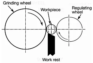
III.CENTERLESS GRINDING Center less grinding is defined as dimensioning of outer diameter of cylindrical parts. It is a kind of grinding operation where there is no collet or chuck for holding the work piece.
The main components of center less grinding machine are grinding wheel and regulating wheel shown in the fig 1 Work piece is rolled in between these two wheels.
Fig.1 Centreless grinding operation
End feed center less grinding machine is used in machining of engine valves. In end feed center less grinding work piece is feed axially on one side comes to rest on back stopper on other side.
In center less grinding machine job is placed on the supporting blade. When the regulating wheel and grinding wheel rotates in clockwise direction job rotates in counter-clockwise direction. Due to this rolling action the work piece is pulled inwards. This motion can be stopped by back-stopper provided parallel to the axis of regulating wheel as shown in Fig .2
Fig .2 Centreless grinding operation
IV.CENTERLESS GROOVEGRINDING MACHINE
Grinding machine used for grooving operation in engine valve manufacturing is also a kind of end feed center less grinding machine. In thisregulating wheel, supporting blade and end stopper are stable and grinding wheel is movable through which the groove diameter can be controlled.
Both groove grinding and end chamfering operations are done in groove grinding machine. Here end stopper is connected with pneumatic cylinder. The end stopper is used for in feed mechanism and ejection of machined work piece.
V. PROCESS CAPABILITY CALCULATION Process Capability index value (Cpk) iscalculated statistically using Statisticalprocess Control sheet and it is validatedagainst the Sigma value to determine therejection level of a product. The Cpk calculation is done with the use of Upper SpecificationLimit (USL), Lower Specification Limit (LSL) of a product, given from the customer side. Byusing these specification limits, USL and LSL, the Cpu and Cpl are calculated. Cpu is nothingbut a statistic, which related the differencebetween USL and the centre line to theStandard deviation (σ). Cpl is alsoa statistic which relates the difference betweenthe centre line and LSL to the Standard deviation (σ). The formula for calculating Cpuand Cpl is given below:
Sigma is the standard deviation value (σ)and X is the average of the sum of all thevalues, i.e., mean of all observed values. Fromthe calculated Cpuand
Cplvalues, one candetermine the Cpkvalue from the formula, shown below:
Cpk= Minimum (Cpu, Cpl)
The minimum value is taken for the Cpkcalculation because, it indicates whether or notthe process being analysed is capable ofproducing little or no defects. The higher thenumber, the less likely it will be defectives areproduced.
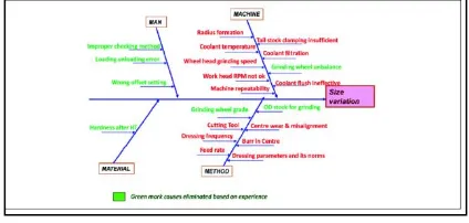
VI.CAUSE AND EFFECT DIAGRAM The cause and effect diagram clearly denotes the causes in 4 M s for a single effect of Size variation fig 3. These causes are labelled in green and red colors, where green color causes can be eliminated by proper training and experience and red color causes plays an important role in size variations of a product. By eliminating the green color labeled causes from the Cause and Effect diagram, we get both significant and insignificant causes, for the variations to occur in a grinding machine.
Fig.3 Cause and Effect Diagram
The experimentation is carried out in a firm, where a numerous products are being manufactured. In that firm, a product is manufactured with more variations in size and they are facing lots of rejection. This situation in that firm is merely due to a single operation out of various operations at various stages on the product. The variation occurs only during machining of the same product, after the heat treatment process. The operation is grinding and it is performed in a grinding machine. Hence, this can be taken as an experimental approach to prove the statement.
Fig.4 Cause and Effect Diagram
VII. EXPERIMENTATION
The four major causes, Work head rpm, Dressing frequency and Feed rate are responsible for the variations to occur on a product during the grinding operation. So, an Industrial experimentation is carried out on a grinding machine to eliminate the variations occurring on a product by making some changes on these causes. These four causes are the key parameters in a grinding machine. Hence, an effect can be surely achieved, once a change is made on these causes.
The experimentation is carried out in a firm, where a numerous products are being manufactured.
In that firm, a product is manufactured with more variations in size and they are facing lots of rejection. This situation in that firm is merely due to a single operation out of various operations at various stages on the product. The variation occurs only during machining of the same product, after the heat treatment process. The operation is grinding and it is performed in a grinding machine .Hence this can be taken as an experimental approach to prove the statement.
VIII. OBSERVATION
The ejection rod is not only used for ejection operation, also it acts as end stopper. After machining next operation is ejection. Here end stopper slides forward and pushes down the machined valve and returns back to its rest position for next machining operation. There is no separate ejection system or ejector rod for ejection operation.
results (Cp and Cpk value) obtained for initial condition is shown in fig 5.
Fig.5 Process capability before implementation
IX. ACTION
In previous method the ejector is directly connected with pneumatic cylinder for simultaneous ejection of machined valves. As per the results obtained from experimentation it is clear that each and every time the position of end stopper varies within the limit (150 micron).To avoid this variation the back stopper is kept stable. The ejection operation is done by separate pin. This can be implemented by modifying the design of ejector. The ejector pin is connected with the pneumatic cylinder. The schematic diagram of new end stopper with hole is shown in fig 6. This hole is provided for sliding of ejection pin.
Fig.6 Ejector rod diagram
The schematic diagram of ejection pin is shown in fig7. This ejection pin is connected with pneumatic cylinder for sliding motion. By implementing the above method there is no variation in ejector position at rest time. Even though there isno variation in end stopper position.
Fig.7 Ejector pin diagram.
There is some defection in ejection rod.This deflection is due to machining forces and vibrations in machine. These variations limits within 50 micron.
The data obtained after implementing this mechanism is collected. The result and improvement in process capability is shown in fig8. From the result the Cp value for implemented process is greater than 1. Therefore the process is capable.
Fig.8 Process cabability after implementation.
X.RESULTS AND DISCUSSION
The Process Monitoring Chart and Statistical Process control are the helping tools for performing such a huge process. The every improvement in the process cycle is noticedand implemented for the permanent achievement in the quality of the product.
rejection from 12.56% by10.38 %. The rejection details are shown in table 1
Table 1. Rejection Details
XI.CONCLUSION
This improvement in the quality not only gives customer satisfaction, it also gains more profit to the organization. The back tracking of the finished product is minimum. Hence this makes a way for reducing the time constraints.
The available time increases as a result ofreduction in the re-work and backtracking ofthe products, the productivity increases rapidly.
If all these are achieved in the machine, thecost of a product will play a major role. The organisation can give a product at acompetitive price, than other firms and at the same time, deliver at a world class products.This methodology is applicable for any kindof grinding machine for to improve the qualityof the product. The four significant causes canbe made into insignificant, if the analysis and approach to the existing problem in a right way.This method has to be done with carefulpremeasures and with the knowledge of theemployer.
REFERENCES
1. ASM Handbook, Machining Process, Vol. 16, pp. 424-435.
2. Factors for Selecting Right Grinding Wheel [online],
availableathttp://www.grindwellnorton.co.in/Grindi ngTech/pdfs /FactorsAffectSelection.pdf.
3. Gijo E V (2005), “Improving Process Capability of manufacturing Process by Application of Statistical Techniques,” Quality Engineering, Vol. 17, No. 2,pp. 309-315.
4. Grinding Machine Details [online], available at
http://metalwebnews.com/
machine-tools/ch5.pdf5. Grinding Trouble shooting [online], available at http://www.nortonindustrial.com / uploaded Files/S Gindnortonabrasives/ Documents Tool room / %20Selection%20Chart%207505.pdf.
6. LinkeB (2008), “Dressing Process Modelfor Vitrified Grinding Wheels”, Vol. 57,pp. 345-348.