Volume-5 Issue-2
International Journal of Intellectual Advancements
and Research in Engineering Computations
Design of Induction Heating System for Rectification of Angular
Welding Distortion
K.Pradeep Kumar1, S.Mahendran2, M.Pradeep2, N.Shameer Ahamed2, P.Vignesh2.
1Assistant Professor, 2UG Students,
Department of Mechanical Engineering, Nandha Engineering College, Erode-52,
Tamil Nadu, India.
1
Abstract: Angular distortion is the one of most challengeable distortion. Various methods are currently being used to control and decreases angular welding distortions because during and after welding is an important aspect of construction and quality. These experimental results have ability to reduce the angular distortion for 8 mm and 10mm thick AH36 steel plate and effectively. In this affects encountered in the use of thin plate ability to decrease distortion within greatest bending occurs. In this application, have been evaluated and its benefits in reducing the rework time have been established. This system models have used as a tool to decide the optimum speeds to decrease the resulting distortion of steel plate after being subjected to the both welding and induction heating processes.
Keywords:Induction heating, Angular welding distortion.
I. INTRODUCTION
Welding is one of the most commonly used joining processes in the fabrication industry. Welding distortion is a result of the non uniform expansion and contraction of weld metal and base metal during the heating and cooling of the welding process is a major concern during the fabrication of welded structure. Welding distortion causes complex consequences most of which are detrimental during fabrication and service. Distortion can be defined two categories in-plane and out-of-plane distortion, there are a number of modes of distortion each of which can significantly affect the accuracy of fit up for the structure. Many structures are constructed using an
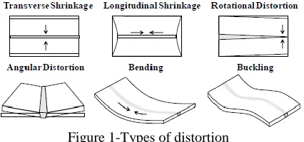
assembly, and consequently distortion can be detrimental when the welded sub-structures have to be aligned and joined together. In many cases, additional costs and schedule delays are incurred from straighten welding distortion. Therefore, rectificationof welding deformation have become of critical importance. Fig1 Welding distortion may be following types as shown below:
Figure 1-Types of distortion
Welding current is the most important of variable welding, because it is controls the burn off rate of electrode, fusion depth and welding geometry. Welding voltage determines the shape of fusion zone and welded reinforcement height. Welding speed is defined as the rate of travel work piece under electrode.
In [1]Induction heating has been used for a number of years for correction the plate distortion, and has been shown to have a number of advantages over using flame straightening, including improved repeatability, increased productivity and the potential for process optimization in this project induction heating system through rectification welding distortion.
Mechanical Property
Tensile strength(Rm): 490-630MPa
Yield strength(Re): 355min
Elongation(A%):21
Chemical Composition %
Grade C
max Si
max
Mn
P
max S
max Cu
max
AH36 0.18 0.50 0.90-1.60 0.03
5
0.035 0.35
Als min Ti
max Cu
max
V
Ni
max Mo
Max Nb
0.015 0.02 0.35 0.05-0.10 0.40 0.08
0.02-0.05
Table .2
II.LITERATURE SURVEY
[1] Thin plate distortion in the shipbuilding sector has been studied for decades but the problem continues. In addition to this there has been a gradual move to include more thin plate into the structure. This is plate thickness 2,4,and normally in the form of higher strength steels such as DH36. A thin plate distortion can be brought down to what could be considered manageable levels. To generate the step change and controllable process of heat straightening. [2] Joining processes is an important key factor for the competitiveness of an European shipbuilders joining techniques has a significant impact on material properties and thus on product performance and the quality. Based on research results, practical an industrial application has been developed recently Joining processes is an important key of factor for the competitiveness of an European shipbuilders.
[3]Thin steel reduces topside weight enhances mission and improve performance and vessel stability but this propensity of buckling distortion have increased significantly. At present, several US Navy construction programs are experiencing high rates of buckling distortion on thin steel structures. Northrop Grumman Ship Systems has been undertaken a comprehensive assessment of lightweight of structure fabrication technology. Shipboard applications of lightweight
[4] Distortion induced in thin plate continues to create adverse performance effects in the shipbuilding industry. A number of issues have been reviewed, along with potential tools to reduce distortion, practically and theoretically. Many of the factors described are management-control issues as the technology is now well established. This probably encompasses about 80% of the solution. Two key issues have been highlighted. If tackled at the source, then this will start to reduce the remaining 20% of the problem.
[5] The technique controls distortion by applying thermal stresses in front of the weld pool to counteract the stresses induced in the structure by welding. A combination of finite element modeling and experimentation has been used to find a thermal tensioning arrangement that reduces distortion by 50% in 4 mm butt welded steel plates using arc welding.
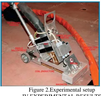
III.EXPERIMENTAL APPARATUS:
INDUCTION STRAIGHTENING SYSTEMS:
Its an parts fig: 2 consists:
Heat generator
Cooler
Heating unit (also known as
inductor unit)
Operator panel
Cables
Optional system for handheld
Figure 2.Experimental setup IV.EXPERIMENTAL RESULTS
One after each distortion measurement stage, a dataset containing the height of each plate of the pre-defined grid points was obtained. To eliminate of the effect any small difference in the height of the 4 mounting points occurring between each stage of experimentation mean height of the plate were subtract from the measurements to produce an array containing the difference in the height at each point from the mean height of plate. This data set was used as the base from which the angular distortion calculated. The distortion of each plate due to the welding obtained by subtracting the dataset obtained before welding from the dataset obtained after, producing an array of containing the vertical movement of the plate, each point due to the welding process. This is an example of the vertical displacement data showing a very distinct V-shape, characteristic of angular distortion, along the entire length of the plate.
Figure 3- Angular welding distortion
Quantify of the distortion that mean movement of the plate at each transverse measurement point was determined and plotted against the transverse location from the center line. The 3 rows of the array containing the data at the center line and point (+/- 10 mm) from the center line was ignore as the measurements were in the location of the stiffener at experimental welds and tack welds. A best fit straight line was the applied to the data point producing a plot of representing the relative angle to each side of the plate as shown below,
Figure 4.Angular Distortion Data V.WELDING DISTORTION
The results for angular distortion due to welding for the 8mm thick and 10 plate samples display an unusual pattern. However it is proposed that the low welding speeds used which was intend to generated high heat input levels and large levels of the distortion may caused this unexpected pattern. While welding the 8 mm samples, the heated zone was clearly visible on the underside of the plate. Hence they are intentionally high heat input level resulted in a significant rise in temperature through the thickness of the plate. This has reduced the temperature difference between the weld and base material, the difference in thermal contraction resulted in the lower levels of the angular distortion.
Figure 5.Plate Welding Distortion of an 8mm
Figure 6.Plate Welding Distortion of 10mm
The angular distortion results for the 10 mm thick was samples exhibited to the expected trend of distortion. Increasing weld travel speed is decreases. Overall the level of the distortion is lower than that found for 8 mm thick samples, with the 10 mm thick plate samples showing distortion in the range of an 10mm plate 0.831° - 1.329°.
VI.INDUCTION HEATING SYSTEM
To compare the results of the induction heating process at the final value of angular distortion has been subtracted from the post welded value producing an angle of representing the distortion rectification of an achieved using the induction heating process. There is an overall trend of increasing the rectification with reducing travel speed although there is an anomalous value at the 25 mm/s within the 3 mm/s weld speed data set.
Figure 7.Distortion Rectification of 8mm
Figure 8-Distortion Rectification of 10mm
The results obtained for the 10 mm thick exhibit similar trends to the 8 mm thick plate with rectification reducing as induction heating speed is increases. This results also reinforce to the trend of the maximum rectification of reducing as a plate thickness increases with a maximum rectification of an 0.458° the lowest of the rectification of results for the 2 plate thicknesses. Again the induction heating process has not been capable of the eliminating welding distortion as the maximum rectification of observed is 0.458° while themaximum distortion is 1.329°.
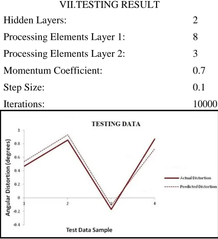
VII.TESTING RESULT
Hidden Layers: 2
Processing Elements Layer 1: 8
Processing Elements Layer 2: 3
Momentum Coefficient: 0.7
Step Size: 0.1
Iterations: 10000
between 0.061° and 0.142° with a mean error of an 0.087°.
Figure10-Final Distortion Sensitivity Study
This sensitivity study for this final model isshows plate thickness to be dominant the factor is affecting the final distortion. This is an expected as this model is predicting the welding distortion within the model and plate thickness is found to be dominant factor of affecting the welding distortion.
VIII.PREDICTION INPUT DATA
To predicted the induction coil travel speeds which minimize the distortion 2 plates were welded the same nominal welding parameters as before but the travel speeds used were 2.25 mm/s and 2.75 mm/s. These welding travel speeds was chosen to the determine whether the models was capable of predicting the respective of distortion values rather than simply memorizing the value for a given set of parameters to process.
Plate
Plate
Thickness
Weld
Travel
Welding
Welding
Measured
Post Weld
no
.
Speed
(mm/s)
Current
(A)
Voltage
(v)
Distortion
(degrees)
1 8 2.25
222
20.6 1.2661
2 10 2.25
218
20.6 1.409
Table .3
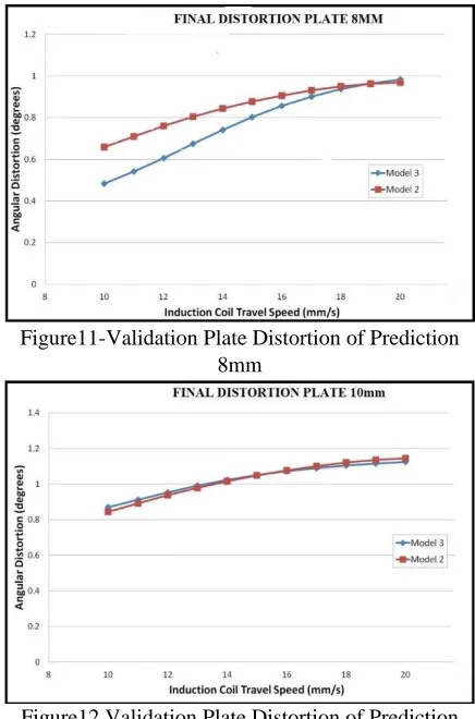
To determine the induction heating system travel speed appropriate parameters were used. Along with theses parameters the induction coil travel speed was varied between 10 mm/s and 20 mm/s in the increments of an 1 mm/s and used an input into each model to the give predicted final distortion over this range of the travels speeds.
Figure11-Validation Plate Distortion of Prediction 8mm
Figure12.Validation Plate Distortion of Prediction 10mm
IX.VALIDATION RESULT
In order to verify the capability of an each model to predict welding distortion and final distortion of 2 plates was welded with the parameters mentioned in the previous section and the predicted result were compared to measured the welding and the final angular distortion values.
Figure 13.Model Validation Results
each case the predicted results have been underestimated to the actual values although not to a significant degree. The maximum and the average errors for the validation results were 0.18° and 0.12° respectively. This leads to conclusion that the post welding distortion can discarded as an input to the predict final distortion as the model does not suffer any loss in the accuracy.
X.BENEFIT ANALYSIS
100 percent safety
Reduce downtime
Smooth and noiseless operation
XI.CONCLUSION
By this innovative method is “design of induction heating system for rectification of angular welding distortion” This experimental trials carried out in this study has demonstrated the technique of using a travelling induction heating to plate rectify weld induced distortion. The results have shown the existence of a critical induction heating travel speed at which maximum rectification bending occurs for 8mm and 10 thick plate and have shown that welding distortion can be completely rectified using this method. The experimental set up used in this trial was able to rectify up to 0.95° of angular 10for the plate signifying that this method may be particularly useful when dealing with steel plate 10 mm thick and below There is no difficulty to handle the equipment.
XII.REFERNCE
[1]Dr.Norman Mc person(2008): Induction heat straightening – A distortion rework reduction tool for thin plate
[2]Roland:Journal on „Advanced Joining Techniques in European Shipbuilding‟.Source: Journal of Ship Production,, Volume 20, Number 3, 1 August 2004, pp. 200-210(11).
[3]J. U. ParkJournal on „Control of Longitudinal Bending Distortion of Built-Up Beams by High-Frequency Induction Heating‟.
[4]McPherson, N.A., Coyle, A., Wells, M: 2008. Induction Heat Straightening - A Distortion Rework Reduction Tool for Thin Plate. Welding and Cutting, 7 (3): pp. 162-166
[5]McPherson,N.A.:2007. Thin Plate Distortion - The Ongoing Problem in Shipbuilding. Journal of Ship Production, Vol. 23 (2). pp. 94–117
[6]Sanderson: Journal of Ship Production, Volume 24, Number 4, November 2008, pp. 177-179(3)
[7]Ramani.S(2014):Effect of process parameters on angular distortion of MIG welded ai6061 plates.
[8]Mahsa Seyyedian Choobi,(2011):Effect of welding sequence and direction on angular distortions in butt-welded plates [9]Y. P. Yang(2014):Material Strength Effect on Weld Shrinkage and Distortion.