Page | 20
Hybrid Algorithmic Approach for Medical Image
Compression Based on Discrete Wavelet
Transform (DWT) and Huffman Techniques for
Cloud Computing
Prof D. Ravichandran
1, Ashwin Dhivakar M R
2, Dr. Vijay Dakha
31Dept of Computer Science and Engineering , Aurora Technological and Research Institute (ATRI), Hyderabad, India 2
Dept of Computer and System Sciences, Jaipur National University, India
3Professor and Head of the Department, Computer Science and Engineering, Jaipur National University, India
Abstract— As medical imaging facilities move towards complete filmless imaging and also generate a large volume of image data through various advance medical modalities, the ability to store, share and transfer images on a cloud-based system is essential for maximizing efficiencies. The major issue that arises in teleradiology is the difficulty of transmitting large volume of medical data with relatively low bandwidth. Image compression techniques have increased the viability by reducing the bandwidth requirement and cost-effective delivery of medical images for primary diagnosis.Wavelet transformation is widely used in the fields of image compression because they allow analysis of images at various levels of resolution and good characteristics. The algorithm what is discussed in this paper employs wavelet toolbox of MATLAB. Multilevel decomposition of the original image is performed by using Haar wavelet transform and then image is quantified and coded based on Huffman technique. The wavelet packet has been applied for reconstruction of the compressed image. The simulation results show that the algorithm has excellent effects in the image reconstruction and better compression ratio and also study shows that valuable in medical image compression on cloud platform.
Keywords—Wavelet Packet, Discrete Wavelet Transform (DWT), Lossless image compression, Medical image, Huffman coding, Cloud computing.
I. INTRODUCTION
In recent years, many studies have been made on wavelets. An excellent overview of what wavelets have brought to the fields as diverse as biomedical applications, wireless communications, computer graphics or turbulence, is given in [1].
Image compression is one of the most visible applications of wavelets [2]. It is well known that medical imaging facilities
move towards complete filmless imaging and that compression plays a vital role for storing, transferring and sharing the patient's images across the computer system for primary diagnostics [3]-[6].
Compression is the process of reducing large data files into smaller files for efficiency of storage and transmission. In general, image compression techniques can be classified into two types, namely, lossy and lossless. In lossless image compression, the reconstructed image from the compressed data is identical to the original image. In lossy compression, the reconstructed image from the compressed data is not the same as that of original image. They are various techniques and methods employed for image compression in both lossy and lossless. Although lossy compression techniques yield high compression ratios, the medical community has been reluctant to adopt these techniques due to legal risks and they prefer to use lossless compression techniques despite low compression rates. The aim and goal of the compression algorithm is to maximize the compression ratio and minimize the mean square error of the image [7]-[9].
ISSN: 2454-1311
Page | 21
IstLevel Decomposition 2ndLevel Decomposition 3rdLevel Decomposition (a) Coding Section
(b) Decoding Section
Fig. 1 The process of Image Compression based on Wavelet Transform
This paper is organized as follows. Section 2 discusses the fundamentals of Discrete Wavelet Transform (DWT). Section 3 talks about the proposed work and research methodology of the hybrid algorithm. Section 4 cites the performance and analysis of the implementation steps of the proposed algorithm. Section 5 gives the conclusion and future work.
II. DISCRETE WAVELETS TRANSFORM
Wavelets are functions defined over a finite interval and have an average value of zero. The basic idea of the wavelet transform is to represent any arbitrary function (t) as a superposition of a set of such wavelets or basis functions. These basis functions or baby wavelets are obtained from a single prototype wavelet called the mother wavelet, by dilations or contractions (scaling) and translations (shifts). The main feature of DWT is multiscale representation of function.
By using the wavelets, given function can be analyzed at various levels of resolution. The DWT is also invertible and can be orthogonal [11]. Wavelet transform has emerged as very powerful tool for data compression [12].
An image is a two Dimensional signal (2D) and that is considered to be matrices with N rows and M columns. In wavelet transform, decomposition of an image consists of two parts, one is lower frequency or approximation of an image (scaling function) and another is higher frequency or detailed part of an image (wavelet function). At every level of decomposition, the four sub-images are obtained, the approximation (LL), the vertical detail (LH), the horizontal detail (HL), and the diagonal detail (HH).
Then all the coefficients are discarded, except the LL coefficients that are transformed into the second level (Fig 2). To achieve the required compression ratio the LL coefficients are passed through a constant scaling factor [13].
DWT is computed with a cascade of filtering followed by a factor 2 sub sampling [14]. In Fig 3, h (n) and g(n) denotes low-pass and high pass filters respectively, ↓2 denotes sub sampling. DWT algorithm for two-dimensional pictures is similar. The DWT is performed firstly for all image rows and then for all columns as shown in the Fig 3.
Fig. 2 Sub band notations in the hierarchical Wavelet Transform
The input signal (image), the high frequency components and low frequency component are denoted by X (n), g (n) and h (n) respectively.
After applying forward discrete wavelet transform, one can employ proper method to process the image coefficients for achieving effective compression [15]. For reconstructing (Fig 4) the coefficients are rescaled followed by padding zeros and then passed through wavelet filter.
Fig. 3 Forward-DWT (Sub band Decomposition of Two Level 2D-DWT)
Fig.4 Inverse-DWT (Sub band Reconstruction of Two Level 2D-DWT)
Original Image
Forward Discrete Wavelet Transform
(FDWT)
Quantization Entropy Coding Bit Stream Output
01010101
Reconstructed Image
Inverse Discrete Wavelet Transform
(IDWT)
ISSN: 2454-1311
Page | 22
III. PROPOSED WORK AND ENVIRONMENT
USED
The research methodology of the proposed work and algorithm steps are summarized as follows:
1. Load Image in MATLAB using Image Acquisition 2. Covert RGB to Gray scale and draw histogram of the
original image.
3. Apply multilevel decomposition using 2D- DWT based on HAAR mother wavelet.
4. Apply histogram probability reduction function on RGB components using Mean intensities.
5. Apply Image quantization
6. Calculate probability index for each unique quantity. 7. Calculate unique binary code of Huffman code for each
unique symbol.
8. Apply Huffman compression using Huffman tree. 9. Calculate CR, MSE and PSNR.
The following figure gives the visual and quantitative results of the method considering the hybrid transformation for block size 32x32. The test medical image (X-ray hand.jpg) is compressed and decompressed using the proposed method. The following figures depict the output of the algorithm in the sequence of execution.
Figure 6 shows the original image and its gray scale converted form (RGB to YCbCr transformation for the block size of 32x32). The histogram of the image is used as reference to evaluate the mean squared error of the image.
Fig. 6 Original Image and its Histogram
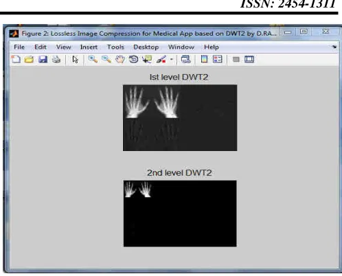
Figure 7 depicts the decomposed image after applying forward Discrete Wavelet Transform in the First level and second level of DWT2.
Fig. 7 Decomposed Image after applying FDWT
Figure 8 shows the reconstructed image after applying dequantization, Huffman decoder and Inverse Discrete Wavelet Transform (IDWT2). The mean squared error of the image between original and the reconstructed image along with the histogram is displayed in order to find out the visual and quantitative performance of the proposed compression algorithm.
Figure 8 Reconstructed image and its Histogram
IV. RESULTS AND DISCUSSIONS
ISSN: 2454-1311
Page | 23 Xray_hand. CT_Brain. MRI_head US_Liver Xray_Chest CT_Brain(png)
results. The proposed method is implemented in MATLAB-2014a. The input images used in the experiments include X-ray hand.jpg, CT brain.gif, MRI head.jpg, US liver.jpg, X-X-ray chest.jpg, and CT brain.png format.
Fig. 9 Bench mark test medical images
Here compression ratio is measured in terms of Bits Per Pixel (bpp) and image quality in terms of PSNR and visual fidelity index [2]. Performance parameters of the images are determined by measuring the compression ratio, peak signal to noise ratio and mean square error of the compressed images. Table-1 summarizes the experimental performance under different image formats of medical images.
TABLE I. EXPERIMENTALPERFORMANCE
UNDERDIFFERENTIMAGE FORMATSOFMEDICAL
IMAGES Types of Image s Image Forma t
MSR PSNR
in db Or igi na l siz e Com pres sed size (kb) CR Space Saving (%) X-ray hand jpg/jpe g 2.743
9E-27 313.75 16 K B
4 4 75
CT
Brain gif
2.801
2E-27 313.66 16 K B
4 4 75
MRI head
jpg/jpe g
3.531
0E-27 312.65 12 K B
4 3 66.7
US-Liver
jpg/jpe g
3.513
0E-27 312.67 12 K B
4 3 66.7
X-ray chest
jpg/jpe g
7.908
3E-27 309.15 12 K B
4 3 66.7
CT
brain png
8.757
1E-27 308.71 20 8K B
4 52 98
The peak signal to noise ratio (PSNR) is the ratio between a signal's maximum power and the power of the signal's noise. PSNR is most easily defined via the mean squared error
(MSE). Given a noise-free m×n monochrome image I and its noisy approximation K, MSE is defined as:
The PSNR (in dB) is defined as:
Here, MAXI is the maximum possible pixel value of the
image. When the pixels are represented using 8 bits per sample, this is 255. Figure 10 shows the comparison of PSNR versus types of medical image formats. Medical images which are stored in the JPEG formats give better PSNR values than those that are stored in the PNG format.
Figure 10 PSNR versus Types of Medical Images Compression ratio and Space savings
---
Fig. 10 Comparison of PSNR versus types of medical image formats.
The compression ratio is the ratio of original image to the compressed image. The space saving of a compression algorithm can be calculated in the following formula.
ISSN: 2454-1311
Page | 24
Fig. 11 Percentage of space savings versus Types of Image Formats
V. CONCLUSIONS AND FUTURE WORK
In this proposed paper, we are using hybrid algorithmic approach for medical image compression based on multilevel decomposition using Haar wavelet transform and Huffman variable entropy coding and the image reconstruction is done with wavelet packet. The experimental results show that the proposed hybrid algorithmic approach provides high compression ratio, least mean square error (MSE) and better Peak Signal to Noise ratio (PSNR) between original and reconstructed image. There are various possible directions for future investigations using evolutionary computation such as Fuzzy Logic, Genetic Algorithms (GA) and Artificial Neural Networks (ANN) in order to optimize compression techniques.
ACKNOWLEDGMENT
The authors would like to express their gratitude to the management of Aurora group of colleges, Hyderabad where this work was performed and thank Dr Suresh Babu, Professor in CSE, for helpful discussions during the course of this work.
REFERENCES
[1] Proc. IEEE (Special Issue on Wavelets), vol. 84, Apr.
1996.
[2] S. Grgic, M. Grgic, and B. Zovko-Cihlar,“Performance Analysis of Image Compression Using Wavelets,” IEEE
Trans. Industrial Electronics, vol. 48, no. 3, pp. 682-695,
June 2001.
[3] G.C. Kagadis, C. Kloukinas, K.Moore, and W.R. Hendee, “Cloud Computing in Medical Imaging,”
American Association of Physicists in Medicine, vol. 40,
no.7, pp 1-11, July 2013
[4] A. Paul, T.Z. Khan, P. Podder, R.Ahmed, and M.M. Rahman,”Iris Image Compression using Wavelets Transform Coding,” IEEE- 2nd Int Conf on Signal
Processing and Integrated Networks (SPIN)-15 ,
pp.544-548, 2015.
[5] Z.Y Songyu, Y.G.Zhou and Y. Mao , “Medical Image Compression Based on Wavelet Transform,” IEEE-
Conf. Proceedings of ICSP '98, pp. 811-814, 1998.
[6] L. Bo, and Y. Zhaorong, “Image Compression Based on Wavelet Transform,” IEEE- Int Conf on
Measurement, Information and Control (MIC),
pp.145-148, May 18-20, 2012.
[7] J. Zukoski,T. Boult, and T.Lyriboz, “A Novel Approach to Medical Image Compression,” Int. J of
Bioinformatics Res and App, vol.2, no.1, pp. 89-103,
2006
[8] C.Doukas and I.Maglogiannis, “Region of Interest Coding Techniques for Medical Image Compression’”
IEEE Engineering In Medicine And Biology Magazine,
pp. 29-35, Sep/Oct. 2007.
[9] M. Antonini, M. Barland, P. Mathieu, and I. Daubechies, “Image coding using the wavelettransform,” IEEE
Trans. Image Processing, vol. 1, pp. 205–220, Apr.
1992.
[10] K. K. Simhadri, S. S. Iyengar, R.J.Holyer, M. Lybanon, and J.M. Zachary, Jr., “Wavelet-Based Feature Extraction from Oceanographic Images ,” IEEE Trans.
Geoscience and Remote Sensing, vol. 36, no. 3, pp.
767-778, May 1998.
[11] W.Yannan, Z. Shudong, and L. Hui, “Study of Image Compression Based on Wavelet Transform,” Proc.
IEEE- Fourth Int Conf on Intelligent Systems Designand Engineering Applications, pp. 575-578, 2013.
[12] S Mallat, “A theory of multiresolution signal decomposition: The wavelet representation,” IEEE
Trans. Pattern Anal. Machine Intell.,vol. 11, pp. 674–
693, July 1989.
[13] S Mallat, “Multifrequency channel decomposition of images and wavelet models,” IEEE Trans. Acoust.,
Speech, Signal Processing, vol.37, pp. 2091–2110, Dec.
1989
[14] B. E. Usevitch, “A Tutorial on Modern Lossy Wavelet Image Compression Foundations of JPEG2000,” IEEE
Signal Processing Magazine, pp. 22-35,Sep. 2001.
M. Smith and S. Eddins, “Analysis/synthesis techniques for subband image coding,” IEEE Trans.Acoust. Speech