IJSRSET511811 | IRCT18 |March-April-2018 [(5)1 : 54-55]
National Conference on 'Innovative Research on Robotics, Circuits and Technology' (IRCT 2018) Organized By : CIrcuit Branches of SCSVMV, (EEE, ECE, EIE & Mechatronics) , Kanchipuram, Tamil Nadu, India
In Assotiation with International Journal of Scientific Research in Science, Engineering and Technology © 2018 IJSRSET | Volume 5 | Issue 1 | | Print ISSN: 2395-1990 | Online ISSN : 2394-4099
54
Micro Controller Based Earth Fault Relay
S. Vasudevan1, A. S. Viswanathan2
1M.E. (Power System) Student Department of Electrical and Electronics Engineering Sri Chandrasekharendra
Saraswathi Viswa Mahavidyalaya University - Enathur, Kanchipuram, Tamil Nadu, India
2Assistant Professor Department of Electrical and Electronics Engineering Sri Chandrasekharendra Saraswathi
Viswa Mahavidyalaya University - Enathur, Kanchipuram, Tamil Nadu, India
ABSTRACT
One of the most common electrical motor used in most applications is inductor motor. This paper presents microcontroller based control system for protector of a Induction motor from earth fault. Due to electrical fault the windings of motor get heated which leads to insulation failure and thus reduce the life time of motor. This protection scheme protects the induction motor from earth fault from initial stage of insulation failure. It also measures the leakage current. Three phase induction motors are industry’s workhorses and widely used as electromechanical energy conversion devices. Although induction machines are considered relatively reliable and robust due to their simple design and well-developed manufactures technologies, failure do occur and may severely disrupt industrial process and even lead to disastrous accidents. To prevent these failure happen, many techniques have been developed for early condition monitoring. The computer based protection methods are costlier then old classical methods and complex. Hence to protect an Induction, motor easily a microcontroller based fault detection and protection is proposed. The proposed system is tested with setting of values presetted values, from the results, it is observed that the results are satisfactory, reliable gives quick response, cost effective and highly resatile.
Keywords: Earth fault, Microcontroller, Induction motor.
I.
INTRODUCTIONA large number of motors are being used for general purpose in our surrounding from house-hold equipment to machine tools in industrial facilities. Among all these motor Induction motors are the most widely used motor they are robust, reliable and durable. Although Induction Motors are reliable, they are subjected to some undesirable stresses, causing faults resulting in failure. Failure of such Induction motor may cause plant shutdown, personal injuries and waste of raw material. However, induction motor faults can be detected in an initial stage in order to
prevent the complete failure of an induction motor and unexpected production costs. The main reason for the motor faults are 1. mechanical and 2.electrical stresses. Mechanical stresses are caused due to overloads and abrupt load variations. The electrical stresses may produce stator winding short circuits and final result in a complete motor failure.
discussed by designing motor current signature analysis [MCSA] with wavelet transformer methods. 2.Artificial intelligent fault monitoring approach 3.Fourier spectral analysis using motor current FFT and 4.MATLAB programming for fault frequency methods and 5.Zig Bee based methods are proposed.
The above said methods are simulation base methods. Recently the PLC based protection systems including all variable parameters of three phase induction motor have been proposed. This method is based on computer and programmable integrated circuit (PIC). This reduces most of the mechanical components. But they are highly complex system and costlier. In order to overcome these problems, the induction motor is monitored by using microcontroller which plays a major role. The presented methods monitor the operating induction motor continuously with the minimum interactive of human. Microcontroller based protection is having advantages. Thease are low cost, simple and higher accuracy. The protection of induction motor by different faults such as over/under voltage, over current, over speed, phase failure, frequency and over temperature,earth fault are possible We consider the earth fault in this proposed work.
Types of Motor Failure and Protective Features
These are various components which cause engine disappointment. The most well-known are:
Overload
Single staging
Voltage unbalance
Voltage too high/low
Bearing disappointment
Rapid obligation cycle
Restricted ventilation
Moisture and vibration
On the off chance that mechanical disappointments are wiped out. Shielding the engine windings from over temperature is the prime function of motor protection.
But even bearing failures can result in motor windings failure if not detected in time. There are a number of ways that motors can be protected with respect to the needs of ways that motors can be protected with respect to the needs of plant management. Table I below classifies these functions. There is no substitute for the proper application of motors or proper maintenance. However, protective devices can help you to use the motor to its optimum limits.
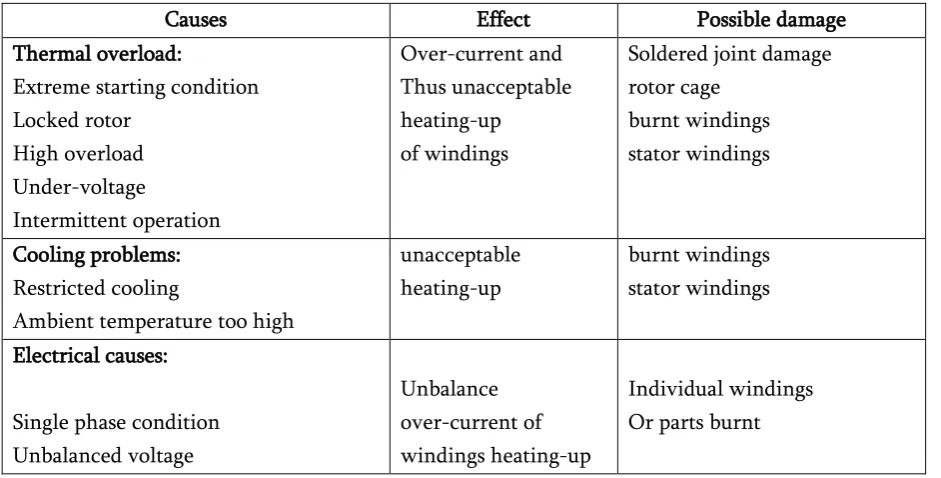
Table 1. Breakdown causes, effects and possible motor damage
Causes Effect Possible damage
Thermal overload:
Extreme starting condition Locked rotor High overload Under-voltage Intermittent operation Over-current and Thus unacceptable heating-up of windings
Soldered joint damage rotor cage
burnt windings stator windings
Cooling problems: Restricted cooling
Ambient temperature too high
unacceptable heating-up
burnt windings stator windings
Electrical causes:
Single phase condition Unbalanced voltage
Unbalance over-current of windings heating-up
Earth fault Shorted turns
Winding short circuit
depending on motor size and bearing damage load Mechanical causes:
Imbalance Mis-alignment
Improperly installed drive(e.g. bearing load of V-belts too high)
uneven wear of bearings
Bearing damage
Necessity for Motor Protection
It could be accepted that legitimately arranged, dimensioned, introduced, worked and kept up drives ought not to separate. In actually, be that as it may, these conditions are barely ever perfect. The recurrence of diverse engine harm varies since it relies on upon distinctive.
Particular working conditions. Measurements demonstrate that yearly down times of 0.5…4% must be normal. Most breakdowns are brought on by an over-burden. Protection shortcomings prompting earth issues, swing to-turn or twisting short – circuits are brought on by overabundance voltage or pollution by sogginess, oil, oil, dust or chemicals.
The Approximate percentages of by these individual faults are :
Overload 30%
Insulation damage 20 %
Phase failure 14 %
Bearing Damage 13 %
Ageing 10 %
Rotor damage 5 %
Other 8 %
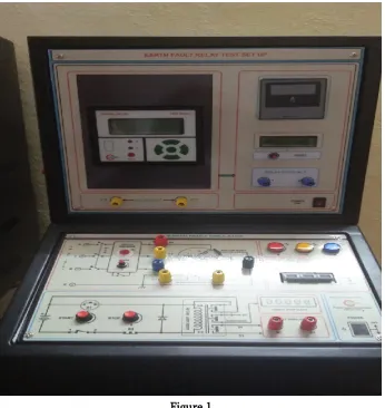
Hardware design and working:
This system of protection of 3 phase Induction motor can be implemented using 8051 Microcontroller, Current transfer, Potential transformer, relay, and LCD display. Circuit gets activates when it gets the supply voltage. Motor will continue running until critical condition occurs. Voltage supply to the MC is
provided through transformer, diode rectifier and 7805 voltage regulator. Current transformer with rating of 5 A provide current equivelent to the supply current to micro controller.
The voltage transformer will provide supply voltage equvue of 12 V Whenever measured value of current exceeds the set value then controller will send signal to relay to turn off motor.
Main Component Used in Circuit 1.Microcontroller 8051 2. Bridge rectifier 3. Induction Motor 4. Relay 12
5. LCD Display (16 x 2) 6. Current Transformer 7. Voltage Transformer.
Description of above component: Microcontroller 8051
Microcontroller receives data from current transformer then convert it from Analog to Digital signal and then compare with the pre programmed valves.
Salient features of 8051 microcontroller are given below.
·Eight bit CPU
·On chip clock oscillator
·4Kbytes of internal program memory (code memory) [ROM]
·64 Kbytes of external program memory address space. ·64 Kbytes of external data memory address space. ·32 bi directional I/O lines (can be used as four 8 bit ports or 32 individually addressable I/O lines) ·Two 16 Bit Timer/Counter :T0, T1
·Full Duplex serial data receiver/transmitter ·Four Register banks with 8 registers in each bank. ·Sixteen bit Program counter (PC) and a data pointer (DPTR)
·8 Bit Program Status Word (PSW) ·8 Bit Stack Pointer
·Five vector interrupt structure (RESET not considered as an interrupt.)
·8051 CPU consists of 8 bit ALU with associated registers like accumulator ‘A’ , B register, PSW, SP, 16 bit program counter, stack pointer. ·ALU can perform arithmetic and logic functions on 8 bit variables.
·8051 has 128 bytes of internal RAM which is divided into Working registers [00 –1F]oBit addressable memory area [20 –2F]o
General purpose memory area (Scratch pad memory) [30-7F]
Bridge Rectifier
We use bridge to get pure DC signal. Bridge rectifier is highly efficient than others. It consists of 4 diodes D1, D2, D3 and D4. When we gives AC supply to the circuit in positive half cycle D1 and D2 become forward biased and it will start conduction at the same time D3 and D4 are reverse biased hence it does
not conduct. In negative half cycle D3 and D4 become forward biased and start conduction and D1, D2 become reverse biased and stop conduction.
Induction Motor
An electrical motor is such an electromechanical device which converts electrical energy into mechanical energy.
Specification: 3 phase squirrel cage induction motor,415v, 0.5HP, 50 HZ,4 pole, speed upto 1500 rpm, Insulation class E
Relay
A relay is an electricity operated switch. Many relays use an electromagnet to mechanically operate a switch , but other operating principles are also used, such as solid – state relays. Relays are used where it is necessary to control a circuit by a separate low-power signal, or where several circuits must be controlled by one signal. In this project we use high precision neumerical relay for protecting the motor from earth fault.
LCD Display
Liquid Crystal Display is used for display the measured reading and if fault it also show on LCD.16x2 LCD is used in circuit. It having 16 character and 2 rows.
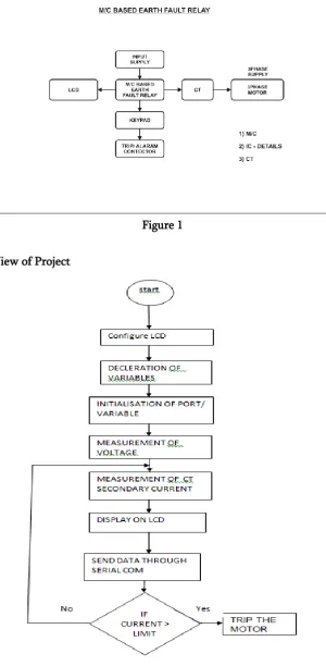
Block Diagram
Figure 1
Figure 1
III.
CONCLUSIONSIn industries due to over-voltage, Under-voltage, Over-current,moisture and over-temperature motor winding may get damage hence this paper has successfully present reliable, fast and efficient system for induction motor protection from earth fault. This system can be implemented in any industries where the protection of motor is essential requirement. The thesis is based on protection of 3 phase induction motor under faulty condition and it is implemented using microcontroller, relay driver circuit and current transformer.
IV.
REFERENCES[1]. Volume: 3 Issue: 11 6287 – 6292
IJRITCC|November 2015,
Availablehttp://www.ijritcc.org Microcontroller Based Protection and Control of Three-Phase
Induction Motor Prof. Ms. Madhuri Balasaheb Zambre(Asst. Prof. Department of Electrical Engineering, Modern College of Engineering,Pune)
[2]. International Journal of Research in Advent Technology (IJRAT) (E-ISSN: 2321-9637) Special Issue National Conference “CONVERGENCE 2016", 06th-07th April 2016 157 A Case Study of Fault Detection and Protection of Three-Phase Induction Motor Yogesh Karhe1, Priyanka Sawant2, Neha Yevale3, Neeta Bhide4, Prof.P.B.Shelke Electrical Engineering (electronics and power), PLITMS Buldana (India)
Amarapur2 1M.tech Student P.D.A college of Engineering Kalaburgi, India 2Professor, Electrical and Electronics Department, P.D.A College of Engineering, Kalaburgi, India
[4]. International Journal of Research in Computer Science and Information Technology (IJRCSIT) 37 PIC Microcontroller Based Speed Control of Three Phase Induction Motor Using Single Phase Supply B. N. Jamadar1, Dr. S. R. Kumbhar2 & D. S. Sutrave3
[5]. International Advanced Research Journal in Science, Engineering and Technology ISO 3297:2007 Certified Vol. 4, Issue 4, April 2017
Copyright to IARJSET