Intrinsic Rotation of a Magnetic Island with Finite Width
Ken UZAWA, Akihiro ISHIZAWA and Noriyoshi NAKAJIMA
National Institute for Fusion Science, 322-6 Oroshi-cho Toki-city, GIFU 509-5292, Japan(Received 19 January 2009/Accepted 14 July 2009)
The rotation direction of a magnetic island in the saturation regime and the underlying physical mechanism are numerically investigated based on a four-field model that includes the effects of both ion and electron diamag-netic drifts as well as parallel ion motion. It is found that diamagdiamag-netic effects vanish inside the island, and that the rotation direction is determined by nonlinearly generated zonal flow. The direction of zonal flow is sensitive to the viscosity and the finite Larmor radius (FLR) effect. The radial mode structure of zonal flow is found to be deformed by that of other modes as the viscosity increases. We have also shown that the FLR effect enhances island rotation toward the ion diamagnetic drift direction through energy transfer to the zonal flow by a nonlinear ion diamagnetic stress tensor.
c
2010 The Japan Society of Plasma Science and Nuclear Fusion Research
Keywords: island rotation, neoclassical tearing mode, two fluid model, zonal flow DOI: 10.1585/pfr.5.S1016
1. Introduction
Tearing modes are resistive magnetohydrodynamic (MHD) instabilities that break the topology of the ideal magnetic field and lead to the formation of helically per-turbed structures called magnetic islands by tearing or re-connecting magnetic field lines around the resonant sur-faces in magnetic confinement devices. Linear theory shows that the classical tearing mode is stable when the stability parameter
Δ= 1
˜
ψ
d ˜ψ dx
x=+0− d ˜ψ dx
x=−0
is negative, which is given by a logarithmic jump of the perturbed magnetic flux around the rational surface [1]. However, in recent low-collisional plasmas, a new type of tearing modes, sustained by helically perturbed bootstrap current, can occur even when classically stable (i.e., the stability parameter is negative). The metastable (linearly stable but nonlinearly unstable) tearing modes are called neoclassical tearing modes (NTMs). NTMs are found to limit the achievable beta in high-performance discharges and deteriorate plasma confinement, leading to plasma dis-ruption. Therefore, much attention has been focused on NTMs both theoretically and experimentally [2–4].
To understand NTM dynamics theoretically, the mod-ified Rutherford equation is often used as the model equa-tion describing temporal evoluequa-tion of magnetic island width,
τs rs
dw dt =rsΔ
+β
p
⎛ ⎜⎜⎜⎜⎝ Δbw
w2+w2 0
−Δp w3
⎞ ⎟⎟⎟⎟⎠ ,
whereτs = μ0r2s/1.22η is the resistive diffusion time at the magnetic surface of radiusrs,ηis the neoclassical
re-author’s e-mail: uzawa.ken@nifs.ac.jp
sistivity,Δis the classical tearing stability parameter dis-cussed above,βp is the poloidal beta atrs, andw0 is the
characteristic island width. The two parameters, Δb and
Δp represent the effects of the bootstrap and polarization currents, respectively. When the sign ofΔpis positive, the polarization term enhances NTM growth. As a typical rep-resentation,Δpis written as
Δp= L2
s kv2 A
Ω(Ω−ω∗i),
whereΩis the island rotation frequency,ω∗iis the ion dia-magnetic drift frequency,Ls is the magnetic shear length, kis the wave number of the mode, andvA=
B2 0/4πnmi
is the Alfv´en velocity [5, 6]. When the island propagates toward the electron (ion) diamagnetic drift, the sign of the polarization term is positive (negative). Therefore, deter-minating the propagation direction of the island is impor-tant for evaluating NTM growth. However, the effects of parallel ion motion and ion diamagnetic drift motion are neglected in these models. Actually, the ion temperature in realistic plasmas is of the order of the electron tempera-ture, so the cold assumption for ions seems to be incorrect. To evaluate the propagation direction of the island more correctly, we have to include these effects in the model equations. For this purpose, we investigate the direction of island rotation in the saturation regime here. The physi-cal mechanism of directional change is also discussed. We found that in some situations, the island can rotate toward the ion diamagnetic drift direction in the nonlinear regime. This behavior originates from the disappearance of dia-magnetic drifts due to pressure flattening inside the island and the generation of zonal flow in the nonlinear regime. We have also shown that the viscosity and finite Larmor radius (FLR) effect are important in determining the island
c
direction.
The remainder of this work is organized as follows. In Sec. 2 we present the model equations used here. Numer-ical simulation results are presented in Sec. 3. In Sec. 4, island rotation in the nonlinear regime and the differences from the linear result are discussed. The mechanism of changes in the island rotation direction is also investigated. We have shown that finally, the island rotates in the non-linearly generated zonal flow. Ion parallel motion is found to contribute to pressure flattening. Finally, the conclusion is given in Sec. 5.
2. Model Equations
Since there is no degree of freedom determining island rotation in conventional MHD models, we have investi-gated the rotation of an island based on a reduced two-fluid model that includes the effects of both ion and electron dia-magnetic drifts. The model equations used here represent a two-dimensional slab version of the four-field model [7], which consists of a set of four equations that describe tem-poral evolution of the magnetic fluxψ, the electrostatic po-tentialφ, the perturbed electron pressurep, and the parallel ion velocityv, i.e.,
∂U
∂t =−[ϕ, U]− ∇J+ν∇
2 ⊥U
−δτ 2
[p,U]+[ϕ, ∇2⊥p]+∇2⊥[p, ϕ],
∂ψ
∂t =−∇ϕ+ηJ+δ∇p,
∂p
∂t =−[ϕ, p]−2βδ∇J−β∇v
+1
2βη(1+τ)∇
2 ⊥p, ∂v
∂t =−[ϕ, v]− 1
2(1+τ)∇p+Dv∇
2 ⊥v,
with vorticity U = ∇2⊥φ, and z-directed current den-sity J = ∇2⊥ψ. The usual Cartesian coordinates (x,y,z) are adopted. The validity of two-dimensional calcula-tion is justified in low-beta plasmas, where the mag-netic field is represented by B = B0ˆz+∇ψ× ˆz, where
B0 is the ambient magnetic field along the z-axis. The
normalization used here is (x, y, t, ψ, φ, n, vi) = (x/a, y/a, vAt/a, ψ/εB0a, cφ/vAB0a, n/n0, δvi/vA).
Here,aandRare the minor and major radii, respectively. cis light speed,ε=a/Ris the inverse aspect ratio,νis the viscosity,ηis the resistivity, and both the equilibrium ion and electron densityn0are constant due to charge
neutral-ity. We suppose that the ion and electron temperatures are constant by introducing their ratioτ = Ti/Te. The
nor-malized parameters δ and βare introduced as two fluid parameters. The former is related to the ion skin depth
δ = (2ωciτA)−1, where ωci = √eB0/cm
i is the ion
cy-clotron frequency, andτA = a/vA is the poloidal Alfv´en transit time. The latter isβ=βe[1+βe(1+τ)/2]−1, where
βe =8πn0Te/B20is the electron plasma beta. One can find
that the ion Larmor radius is related to the cross product of these two parameters, i.e., (ρi/a)2 =2τδ2βe. The operator [, ] denotes the Poisson bracket, [A, B]=∇⊥A× ∇⊥B·ˆz.
3. Linear Calculation
3.1
Numerical settings
In this research, we adopt two-dimensional slab geom-etry as an approximate model for the tokamak geomgeom-etry. Although, we cannot consider an internal kink mode in the slab model, here we focus on the tearing mode that occurs near the magnetic neutral sheet far from plasma bound-aries. Generally, the slab model can capture mainly the most dominant dynamics.
The model equations are solved numerically by us-ing pseudo spectral code. We impose the zero boundary condition for radial directionx, so all components are au-tomatically set to zero at the radial boundary. A finite-differential method is applied in the radial direction, and a periodic boundary condition is imposed for the poloidal directiony. The domain of the numerical simulations is x = [0,1] and y = [0,1]. The number of grids in a simulation box is 400×20. Temporal evolution is cal-culated by using a predictor-corrector method with time stepΔt = 10−3. The pressure and magnetic flux
equilib-rium profiles arepeq(x)=0.25 (1−tanh(x−0.5))/Lp, and ψeq(x)=Lsln[cosh(x−0.5)/Ls]. We have no equilibrium parts for either electrostatic potentialφor ion parallel ve-locityv, i.e.,φ =φ, v˜ = v˜. All calculations described in this article are performed withν=10−6 10−4,η =10−4, andDv=10−4. These numerical values may be large com-pared to the realistic transport coefficients in tokamak plas-mas, and these higher values correspond to hyperviscosity in the numerical calculations. This situation is suitable if these coefficients include the effects of interaction between the island and microscale turbulence. A temperature ratio of unityτ =1 is chosen, and the shear and density scale lengths are set toLs=0.1 andLp =0.15, respectively. The stability parameterΔis positive only for them=1 mode, and the other modes are all linearly stable. From now on, we discuss the rotation frequency of them=1 mode.
3.2
Linear results
First, we examine island rotation by performing linear calculation. All perturbed quantities ˜A(x,y,t) are assumed to vary as
˜
A(x,y,t)= m
Am(x) expi(2πmy−ωmt),
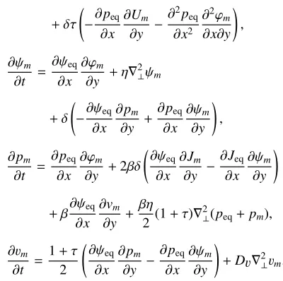
wheremis the poloidal mode number,ωm =iγm+Ωmis the complex frequency,γmis the growth rate, andΩmis the rotation (angular) frequency. Note that the island rotates toward the electron diamagnetic drift frequency whenΩm is positive. The linearized equations are
∂Um
∂t =
∂ψeq ∂x
∂Jm
∂y −
∂ψm
∂y
∂Jeq ∂x +ν∇
+δτ
−∂∂peq x
∂Um
∂y −
∂2p eq ∂x2
∂2ϕ
m
∂x∂y
,
∂ψm
∂t =
∂ψeq ∂x
∂ϕm
∂y +η∇
2 ⊥ψm
+δ
−∂ψeq∂ x
∂pm
∂y +
∂peq ∂x
∂ψm
∂y
,
∂pm
∂t =
∂peq ∂x
∂ϕm
∂y +2βδ
∂ψeq
∂x
∂Jm
∂y −
∂Jeq ∂x
∂ψm
∂y
+β∂ψeq∂
x
∂vm
∂y +
βη
2 (1+τ)∇
2
⊥(peq+pm), ∂vm
∂t = 1+τ
2
∂ψeq
∂x
∂pm
∂y −
∂peq ∂x
∂ψm
∂y
+Dv∇2⊥vm.
We can control the strength of the magnetic fieldB0
in plasmas by changingβ. In Fig. 1, the rotation frequency of them=1 modeΩ(≡Ω1) is illustrated as a function of βfor variousδ. Whenδis large, the rotation frequency be-comes small, indicating that the FLR effect enhances island rotation in the direction of ion diamagnetic drift. Com-pared toδ,βdependence is found to be small. As shown in these results, the island rotates toward electron diamag-netic drift in the linear regime.
4. Nonlinear Calculation
In the previous section, we found that in the linear regime the island rotates toward the electron diamagnetic drift direction. However, in the regime where the island width is quite large as compared to the linear tearing layer width, the linear theory may be invalid. The NTM is in-trinsically a nonlinear instability, therefore it is important to know the direction of island rotation where the nonlin-earity is important. In this section, we discuss the island propagation direction in the nonlinear regime.
Fig. 1 Rotation frequency as a function ofβfor variousδ.
4.1
Propagation direction in the nonlinear
regime
Figure 2 shows the temporal evolution of the rotation frequency (blue line) and width (red line) of the island. The rotation frequency and width are normalized by the lin-ear electron diamagnetic frequency and minor radius, re-spectively. In accordance with the linear results, the island initially propagates toward the electron diamagnetic drift. Since island rotation in the electron diamagnetic direction is weakened by the linear ion diamagnetic drift effect, the rotation frequency is small compared to the linear electron diamagnetic drift frequency. As the island width exceeds the linear tearing layer width and nonlinearity becomes ef-fective, rotation toward the electron diamagnetic drift di-rection gradually weakens. We can observe that at around t =260, the rotation direction changes. Finally, when is-land growth reaches the saturate state, the isis-land rotates toward the ion diamagnetic drift direction.
4.2
Propagation with the zonal flow
In the preceding subsection we found that the island can rotate toward the ion diamagnetic drift direction in the nonlinear regime. Here, we consider the mechanism of the rotation change in detail.
Figure 3 shows the temporal evolution of island poloidal velocity and drift velocities. The red line repre-sents the poloidal velocity of the island, the green one is the electron diamagnetic velocity, the blue one is the zonal flow velocity, and the orange one is the sum of the electron diamagnetic and zonal flow velocities. Note that each ve-locity is averaged over the flux surface. Initially, the island propagates toward the electron diamagnetic direction. We found that as the island width increases, the pressure is flat-tened inside the island. After aboutt=200, the flattening begins to have an effect and the electron diamagnetic drift weakens. Finally, the pressure is totally flattened inside the island. On the other hand, the zonal flow is nonlinearly
Fig. 3 Temporal evolution of island poloidal velocity (red line), electron diamagnetic velocity (green line), zonal flow ve-locity (blue line), and the sum of the electron diamagnetic and zonal flow velocities (orange line).
generated. We find that the poloidal velocity is the sum of the electron diamagnetic drift and zonal flow velocities. Eventually, as mentioned earlier, the pressure gradient is flattened, so the island propagates with the zonal flow.
Snapshots of current density and pressure at two dif-ferent times, (a)t = 267 and (b) t = 500 are shown in Fig. 4. The separatrix (dotted line) is also plotted as a ref-erence. Here,η=10−4,ν=5×10⁻⁶,δ=0.02,β=0.05,
andτ =1.0. The horizontal and vertical axes (x, y) rep-resent the radial and poloidal directions, respectively. The magnetic neutral sheet lies atx=0.5. A uniform magnetic fieldB0lies along thez-axis. Since the pressure gradient
is along the radial direction, the electron (ion) diamagnetic drift moves upward (downward). In case (a), where the island rotation is locked, the pressure is partially flattened in the island. In case (b), the current density is found to show complex structure due to excitation of higher modes. We can observe in the saturation regime that the pressure is totally flattened inside the island, whereas a residual pres-sure profile is observed in traditional models, which do not include the effect of parallel ion motion. We found that parallel ion motion is an important factor in determining the island rotation direction precisely, which is consistent with Ref. [8].
Figure 5 shows the zonal flow velocity in the satura-tion regime as a funcsatura-tion of the viscosity in the saturasatura-tion regime. The island propagates toward the electron dianetic drift in the high-collisional regime where the mag-netic Prandtl number Pr=ν/ηis approximately unity. The
zonal flow velocity monotonically increases with respect to the viscosity. At around ν = 2.0×10⁻⁵, the
propaga-tion direcpropaga-tion changes. The rotapropaga-tion direcpropaga-tion is found to depend strongly on the viscosity.
4.3
Energy transfer to zonal flow
In this subsection, we investigate the underlying mechanism of the viscosity dependence of zonal flow
ve-Fig. 4 Contour plots of current density and pressure at two dif-ferent times, (a)t=267 and (b)t=500.
Fig. 5 Zonal flow velocity in the saturation regime as a function of viscosity.
0 100 200 300 400 500
10-14
10-12
10-10
10-8
10-6
10-4
t
E
km = 0 m = 1 m = 2 m = 3 m = 4 m = 5
(
a
)
Fig. 6 Temporal evolution of the kinetic energy of each poloidal mode for two different viscosity cases, (a)ν=5×10⁻⁶
and (b)ν=3×10⁻⁵.
3×10⁻⁵. In both cases, only them = 1 mode grows in
the linear regime. At aroundt =80, island growth enters the nonlinear phase, and them=0 mode, i.e., zonal flow, is excited through nonlinear mode coupling. The growth rate of zonal flow is twice that of them = 1 mode,
indi-Fig. 7 Radial structures of zonal flow potential inside the island for two viscosity cases, (a) ν = 5×10⁻⁶ and (b) ν =
3×10⁻⁵at different times
t=250 (blue line) andt=550 (red line).
cating that zonal flow is generated mainly from them=1 mode. As seen in Fig. 6 (a), the zonal flow finally becomes the most dominant mode in the saturation regime. In con-trast, we can observe that in case (b) the zonal flow energy decreases due to viscous damping and the zonal flow en-ergy is the same or smaller than the enen-ergy of other modes. In this situation, the mode structure of zonal flow can be affected by that of other modes.
Figure 7 shows the radial structures of zonal flow po-tential inside the island for two viscosity cases, (a)ν = 5×10⁻⁶ and (b)ν = 3×10⁻⁵. Two different temporal snapshots,t =250 (blue line) andt =550 (red line), are plotted for each case. The dotted lines indicate the separa-trix at a given time. In case (a), the radial mode structure is found to maintain a monotonically decreasing function through the temporal evolution. On the other hand, in case (b), the mode structure reverses its functional form in the saturation regime. This is attributed to deformation of the mode structure of zonal flow by other modes, as expected from Fig. 6 (b).
4.4
The FLR e
ff
ect on the rotation direction
Here, we investigate the effect ofδon the rotation fre-quency in the nonlinear regime. Figure 8 shows the ro-tation frequency as a function of island width for variousδ. The viscosity andβareν = 3×10⁻⁵ andβ = 0.05,
Fig. 8 Rotation frequency as a function of island width for vari-ousδ.
Fig. 9 Temporal evolution of energy transfer to zonal flow by the Reynolds stress (blue line), Maxwell stress (green line), nonlinear ion diamagnetic stress (red line), and vis-cous stress (cyan line) for (a)δ=0.01, (b)δ=0.015, and (c)δ=0.02.
stresses for three different FLR parameters: (a)δ=0.01, (b)δ = 0.015, and (c)δ = 0.02. We can observe that as
δincreases, the energy transfer to the zonal flow from the nonlinear ion diamagnetic stress increases. We found that zonal flow generation strengthens due to increase of the nonlinear ion diamagnetic stress.
5. Conclusion
In conclusion, we have shown that the pressure is to-tally flattened inside an island, and the island is carried by nonlinearly generated zonal flow in the saturation regime. This suggests that the rotation direction depends on ion parallel motion, which is not taken into account correctly in conventional models. We found that the rotation direc-tion in the saturadirec-tion regime is sensitive to the viscosity and the FLR effect. As the viscosity becomes large, island ro-tation toward the ion diamagnetic drift direction weakens. This is found to originate from deformation of the radial mode structure of the zonal flow by other modes. We have also shown that the FLR effect enhances zonal flow gener-ation, leading to island rotation toward the ion diamagnetic drift direction.
More analyses including neoclassical effects, e.g., the effect of bootstrap current, are necessary. They will be dis-cussed in future work.
Acknowledgments
One of the authors (K. U.) thanks Dr. M. Sato and Dr. S. Nishimura in NIFS for valuable discussions.
[1] H. P. Furth, J. Killeen and M. N. Rosenbluth, Phys. Fluids6, 459 (1963).
[2] R. J. La Haye, Phys. Plasmas13, 055501 (2006).
[3] A. Isayama, Y. Kamada, T. Ozeki and N. Isei, Plasma. Phys. Control. Fusion41, 35 (1999).
[4] R. Fitzpatrick, Phys. Plasmas2, 825 (1995).
[5] J. W. Connor, F. L. Waelbroeck and H. R. Wilson, Phys. Plas-mas8, 2835 (2001).
[6] R. Fitzpatrick and F. L. Waelbroeck, Phys. Plasmas 12, 022307 (2005).
[7] R. D. Hazeltine, M. Kotschenreuther and P. J. Morrison, Phys. Fluids28, 2466 (1985).