*Corresponding author: L. Muruganandam, Email: [email protected] page 114 of 129
Hydrodynamics in a Liquid Solid Circulating Fluidized
Bed–A Review
Receive Date: 28 December 2018, Revise Date: 12 March 2019, Accept Date: 12 March 2019 Abstract: In this study, the liquid-solid circulating fluidised bed and its performance at various operating conditions were critically reviewed. Hydrodynamic includes pressure drop across the bed, phase hold up distribution, flow regime, flow structure of each phase and solid circulation rate. Detailed analysis of the axial and radial solid distributions, average solid holdup, solid circulation rate, critical transitional velocity for solid at different densities and fluids at various viscosities was discussed. The effect of increasing the liquid viscosity during the heat and mass transfer phenomena in LSCFB has to be studied extensively as the industrial processing fluids are highly viscous.
Key words: LSCFB; hydrodynamics; Solid holdup; Solid circulation rate; Viscosity effect.
DOI: 10.33945/SAMI/JCR.2019.1.114129 Graphical Abstract:
G. S. Nirmala
, L. Muruganandam
*
Department of Chemical Engineering, SCALE, VIT University, Vellore, India, 632014.
Biography:
G. S.Nirmala: Nirmala Gnanasundaram Associate Professor of chemical Engineering, Vellore Institute of Technology Vellore India. Expertise in Liquid Solid Circulating Fluidized bed. Specialized in studies relating to hydrodynamics in a packed and circulating fluidized bed. Designed and fabricated column for two phases and three phase systems. Focusing on the application of LSCFB for biosorption of heavy metals, Phenol recovery, Industrial effluent bio degradation etc.
L. Muruganandam, a chemical engineer working in the area of shock wave applications in Bio and Chemical engineering process. Specialized in membrane development, design and fabrication of Circulating Fluidized bed for environmental treatment like bio-sorption, physical separation of heavy metals, oil impurities from produced water. The research on biodegradation of perchlorate leads to isolation of several species had 9 GEN Publications.
1. Introduction
Solid particles are often of great interest in the chemical process industry, mineral processing, pharmaceutical production, and energy-related processes. Some configurations are available for carrying out such reactions and contacting operations, including fixed bed, packed beds, fluidized beds, and dilute phase transport systems. Among these techniques, the circulating fluidized bed-CFB has come to prominence in the past two decades in terms of significant applications. A typical required configuration is a tall vessel, a means of introducing particles (often solids) usually near the bottom, a sufficient upwards flow of fluid to cause substantial entrainment of particles from the top of the vessel, and a means of capturing a majority of these particles and returning them continuously to the bottom. The term circulating signifies that the particle separation and return systems are integral and essential components of the overall reactor configuration.
In the fluidized bed denotes, the fact that the particles are supported by the fluid, the CFB can be operated in the co-current upward flow mode or fast fluidization mode where there is no distinct or recognizable upper bed surface depending on the gas velocity and solid circulation rate. Although fluidization can be achieved by utilizing either a gas or a liquid as the fluidizing medium, gas beds in the past have received greater attention from the scientific community, because of its industrial applications. The gas fluidized beds are vastly more numerous than those of liquid beds, recently new processes are being studied involving the utilization of liquid fluidized units in the field of hydro-metallurgy, food technology, biochemical
processing, and water treatment. In liquid beds, homogeneous behaviour facilitates the understanding of the basics of fluidization whereas the phenomena in gas beds are dominated in a chaotic manner by the presence of bubbles. LSCFB is a specific type of contacting device having potential applications in the field of food processing, biochemical processing, environmental engineering, petrochemical and metallurgical processing. compared with conventional fluidized beds, circulating fluidized beds had many advantages including better interfacial contacting and reduced back mixing.
consists of riser, downcomer, liquid-solid separator and returns pipe and other auxiliary components. The riser is a fast column operating in a circulating regime and the down comer is a slow column operated either in a fixed or fluidized bed regime.
The critical review [2] on Liquid-solid circulating fluidized bed and Gas-solid circulating fluidized bed had focused the attention of researchers and industrial practitioners for the promising multiphase contactors. Hydrodynamics in a fluidized bed includes pressure drop across the bed, phase hold up distribution, flow regime, flow structure of each phase and solid circulation rate etc. The hydrodynamics depends upon the phase velocities, their orientation, particle characterization, fluid properties and geometry of the fluidized bed. This review study is based on the characteristics studies including, axial and radial solid distributions, average solid holdup, solid circulation rate, critical transitional velocity, flow regimes and characteristics, viscosity effects, and the overall applications of LSCFB.
2. Application of LSCFB
Liquid-solid circulating reactor forms the heart of emerging alkylation processes for the production of motor fuel additives and also for the manufacture of linear alkylbenzene (LAB). Conventionally, the manufacture of LAB and other alkylated olefins and aromatics have been effected through the use of strong liquid acids, such as hydrofluoric acid and sulfuric acid. In LSCFB the hydrocarbon reactants are in the liquid phase which is at high pressure and temperature and it flows concurrently upward with the solid catalyst inside the riser. On reaction, the solids get deactivated and the deactivated solid catalyst is sent to the downcomer continuously where they are regenerated by washing with liquid stream [3].
Continuous recovery of protein from whey solutions containing a downcomer for protein adsorption and a riser for protein desorption, with ion exchange particles circulating continuously between the riser and downcomer was reported [4]. The downcomer could be divided into three zones according to the solid hold up dense phase, dilute phase, and the freeboard. For protein adsorption, the dense phase is the most crucial zone and for preventing the loss of ion exchange particles freeboard zone can be used. Continuous adsorption, desorption, and regeneration of the ion exchange particles were studied based on influence of the operating conditions. Overall recovery of protein was 78.4% by a routine method and increased up to 90% under other conditions with low protein concentrations in the effluent [5].
Separation of the caesium from radioactive liquid waste was studied [6], where the riser is operated in the circulating regime and the downcomer as
slow-moving packed bed ion exchange system for the removal and recovery of 137Cs. It was reported that the relative velocity between the liquid feed flow and the ion exchanger has an influence on the liquid phase mass transfer coefficient to remove the 137Cs from the radioactive liquid waste. Carbonaceous and biological nutrient removal (BNR) from the municipal wastewater by LSCFB is gaining importance. Simultaneous elimination of organic carbon and nitrogen using a circulating fluidized bed biological reactor (CFBBR) has been developed [7, 8]. The system has two fluidized beds, running as anoxic and aerobic processes to accomplish simultaneous nitrification and denitrification with continuous circulation of liquids through the anoxic and aerobic bed. The combination of circulating fluidization and conventional fluidization provides higher liquid-solid contact, mass transfer efficiency, and higher throughput than the conventional fluidization. CFBBR appears to be not only an excellent alternative to conventional activated sludge type BNR technologies but also capable of processing much higher loadings that are suitable for industrial applications.
An alternative approach with potential benefits in the LSCFB system is for the simultaneous reaction and regeneration of the biocatalyst particles without mixing and independent in the two inter-connected FBRs. The LSCFB system offers a great advantage over the conventional packed and fluidized bed reactors for the enzyme-catalyzed reactions. Phenols are found to be highly toxic and carcinogenic in nature present in wastewater. Enzyme-catalyzed reactions provide a number of advantageous over the other techniques like ozone treatment, activated adsorption and chemical oxidation [9, 10]. The experimental result showed that an enzymatic reaction and regeneration of the biocatalyst could be carried out simultaneously and independently in the LSCFB. The biocatalyst particles were soybean peroxidase (SBP) enzyme extracted from soybean seed hulls and entrapped within a mixture of a sol-gel and calcium alginate. Phenol conversion to the extent of 54% was achieved within a very short time period in the 4m high riser of the liquid-solid. This study opens the possibilities for many bioprocesses to substantiate the deactivation of the biocatalyst in the regeneration section.
production of lactic acid. This method eliminates the costly and complex chemical control approach used in conventional techniques. Biosorption of chromium, nickel, copper, and cadmium by alginate beads in circulating fluidized bed [12] using the mixed consortium of Yeast, Pseudomonas aeruginosa, Bacillus subtilis and Escherichia coli. The bio-sorption of heavy metals in an LSFB is not only a cost effective but also a highly efficient alternative to chemical and physical treatments employed for the removal of heavy metal pollutants from contaminated water.
3. Hydrodynamics studies-solid holdup and solid circulation rate
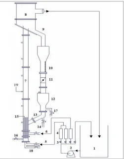
LSCFB usually consist of a riser column with the diameter to height ratio as 1:30 a liquid-solid separator and down comer. The schematic diagram is shown in Fig 1. The riser had pressure tapings at regular intervals connected to a multi-limb or digital manometer to measure the pressure drop in each section of the riser. The base of the riser has two distributors one for primary liquid flow and the other for auxiliary liquid flow into the riser. To get better distribution the primary liquid distributor should occupy 15 to 25 % of the total bed area. The auxiliary distribution has a porous plate which occupies 7 to 10 % of the flow cross-sectional area and has a provision to insert the primary distributor tubes. The liquid and the solid flow rates were controlled independently by adjusting the main and auxiliary liquid flow rates. The auxiliary liquid stream controls the number of particles recirculating from the storage vessel in the riser. Additional liquid from the auxiliary distributor added to riser bottom causes more particles to enter into the riser and each flow rate was measured by a separate rotameter.
Particles from the riser bottom were carried to the top of the riser by the total liquid flow, sum of primary and auxiliary liquid flow. Entrained particles were separated by a liquid-solid separator at the riser top and returned to the storage vessel after being passed through the solid flow rate measuring device. The Liquid leaves the liquid solid separator at the liquid outlet placed at the separator to the reservoir. In the solid circulation measuring section, the column was graduated along the length of the ball valve. During the operation when the ball valve was closed, it enabled the solid collected in the calibrated tube for a known height and the corresponding time was noted. The solid feeding pipe was connected to the riser well above the auxiliary liquid distributor at a particular angle and the other end was coupled to the bottom of the conical section of the storage vessel.
Two long vertical tubes connected together to form a closed loop; fluid and particles, introduced at the top,
are circulated in a clockwise direction by means of a propeller situated near the top of the down-flow tube, a drain valve at the bottom enables the contents to bed discharged. Using this simple construction they developed a one-dimensional momentum balance for estimating the solid circulation rate.
Experiments in a liquid solid transport bed, 1.21 m height, 20 cm width and a thickness of 1.2 cm were done to study the mechanism of particle cluster and disintegration [13]. The nylon spheres of 2.5 mm diameter were fluidized in water with the varying amount of glycerine. The liquid superficial velocity was operated in the range of 2-8 times the particle terminal velocity. The authors concluded that the particle cluster continuously forms and disintegrate in the liquid solid transport bed. Particles organize and gather in a vertical direction when a cluster forms with the doublets being most common. The degree of clustering is found to increase as the solid holdup increases. No information was mentioned about the lifespan of clusters as the duration is very small.
Figure 1. Schematic diagram of the experimental setup. (1) Liquid reservoir; (2) Pump; (3) Valve; (4) Flow meter; (5) Primary Liquid Inlet; (6) Auxiliary Liquid Inlet; (7) Riser; (8) Liquid-Solid Separator; (9) Solid Return Pipe; (10) Graduated Scale (mm); (11) Butterfly Valve; (12) Downcomer; (13) Return leg; (14)Solid Discharge; (15) Stand Pipe Distributors; (16) Air Inlet Provision; (17) Tertiary Liquid Inlet Provision; (18) Drain; (19) Pressure Tappings.
mm i.d and 3.0 m long liquid solid riser. The performance of a riser as a reactor was compared with stirred tank and proved high conversion in LCSFB riser. This study gave a clear foundation for further studies on LSCFB hydrodynamics. The experimental results showed that LSCFB could be classified into conventional particulate fluidization, circulating fluidization, circulating fluidization and transport regimes. Flow regime map was proposed defining dimensionless superficial liquid velocity and dimensionless particle diameter as
3 1
1 2 1
*
g
U
U
l(1)
3 1
2 1
1 *
g
d
d
p p(2)
This regime map gives four different regimes for liquid solid systems. The bed is initially fixed bed when U1* is low on increasing the velocity beyond the minimum fluidization velocity it transforms to fluidization regime by further increasing the velocity it enters into circulating fluidization regime and then enter into transport regime with a further increase in U1*.
The observed radial nonuniform flow structure in the circulating fluidization regime was different from the conventional fluidization regime and the transport regime. The results showed that the cross-sectional average bed voidage at different bed level was found to be same indicating uniform flow structure along the axial direction and the radial uniformity of the liquid velocity increases with the increase in superficial liquid velocity and with the increase in particle circulation rate. The calculated bed voidage, slip velocity, and relative drag coefficient from the experiment was compared with the empirical correlations based on homogeneous fluidization. The core-annular flow model based on the earlier studies of flow characteristics [16] describes the radial nonuniform flow structure in an LSCFB. The model stated higher liquid velocity, higher particle velocity, and higher bed voidage in the core region and low values in the annular region. A radial uniformity indexed [17], has been proposed to characterize the radial flow structure; this uniformity index has the value less than 1 signifying more non-uniform radial structure. The similarities and differences between L-S and G-L-S were also discussed.
The macroscopic flow structure of the LSCFB over a range of liquid velocities and circulating mass fluxes was reported by [18] to be 49 mm diameter and 4 m high circulating fluidized bed with glass particles of diameter 93-182µm. From systematic measurements
of the static pressure, it is found that the axial distribution of the solid holdup is always uniform throughout the riser. The existing flow model obtained in batch liquid solid fluidized beds becomes inapplicable to describe the relationship between the liquid solid slip velocity and the bed voidage. The image analysis of the luminous intensity of the photographs taken through the riser for different operating states were analysed using the fractal and power spectral density distribution. The results indicated that the formation of the large scale aggregates takes place at a velocity higher than the particle terminal velocity which leads to a slight decrease of complexity in the microscopic spatial distribution of bed voidage.
8 . 0 8 . 025
.
0
1
l sU
G
(3) where
1/3 l l s sg
G
G
(4)
3 1 1 21
g
U
U
l (5)Significant contribution to hydrodynamics in LSCFB is mainly due to works carried by [21], [22] [23], [24], [25], [26] and gas-liquid-solid circulating fluidized bed by [27], [28], [29] had sprouted the attention of researchers and industrial practitioners towards this areas.
The radial nonuniformity index (RNI) to quantify the non-uniformity in radial variations of flow parameters in fluidized beds and other multiphase flow systems was proposed [30]. Using RNI radial distribution of local solid concentrations and solid velocities from GSCFB and LSCFB were examined. The results showed that the gas-solid riser has significantly more flow segregation in the radial direction with higher RNI values than the liquid solid riser.
The radial flow structure using a fibre optical probe in an LSCFB riser was obtained at four different heights [24] for glass beads and plastic beads. In the radial direction of the riser, non-uniformity exists in the solid holdup distribution, with high solid holdup near the wall. The non-uniformity increases with the increase of solid flow rate and decrease of the liquid velocity. This observation was similar to the results reported in [16]. The authors reported under the same cross-sectional average solid holdup, the radial profiles of solid holdup are the same for each type of particle system under different operating conditions, but the lighter particles show flatter radial profile than the relatively heavier particles.
To further quantify the radial nonuniformity, the concept of RNI was explained in [30]. The experimental results by [31] depict the radial distribution of liquid velocity using a dual conductivity probe predicted the similar result of earlier works on radial flow. The result also showed that RNI value seems to be much higher in the liquid solid circulating fluidized bed regime compared with the conventional fluidization and transport regime indicating nonuniformities in the LSCFB regime.
The transport velocity and average solid holdup in a 76.2 mm diameter and 3 m high LSCFB by using various solids was studied [32]. The critical transport velocity for circulating fluidization was found to be
the function of solid properties and independent of auxiliary liquid velocity. They reported uniform axial solid holdup and also observed that the average solid holdup increases with an increase in solid circulation rate, decreases with the increase in liquid velocity and particle diameter. A correlation was developed [33] to estimate the average solid holdup and transport velocity in terms of dimensionless particle diameter, solid circulation rate and superficial liquid velocity as
0.53 0.37
17 . 0 ) 505 . 0 ( p l s d U Gs
(6)
_ 0.76045
.
0
p p crd
gd
U
(7)Where
G
sand
U
l
are represented by the equations 4 and 5
3 / 1 2
Fluidized Bed based on three parameters: the superficial liquid velocity (Ul), the normalized superficial liquid velocity (Ul/Ut) and the excess superficial liquid velocity (Ul-Ut). The results showed that the excess superficial liquid velocity (Ul- Ut) among those three parameters is a more appropriate parameter to evaluate the effects of the particle properties on the solids holdup (εs), facilitating general and direct comparisons for different types of particles. A discussion on the force balance of the particles revealed that the excess superficial liquid velocity (Ul-Ut) is approximately equivalent to the average particle velocity when the solids holdup (εs) is less than 0.1.
The effect of axial solid holdup for different viscous solutions at four different locations along the length of the riser for glass bead-glycerol system at 1.36 cP [38]. It is observed that there exist a similar flow structure in the axial distribution of solid hold up at the lower section (H=0.6 m), the middle section (0.9 m and 1.2 m), and the upper section (H=1.5 m) of the riser for the given primary velocity. It can also be observed that at every axial position solid hold up is
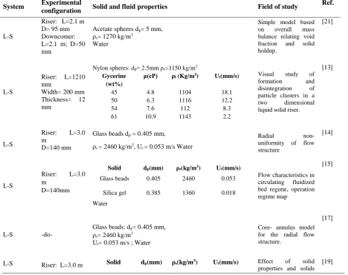
found to increase with an increase in auxiliary velocity as the movement of solids in the return pipe increases with increase in auxiliary velocity for the given fluid with viscosity 1.36 cP. Further, it is observed that there is a considerable height of dense phase at the bottom of the test section for all operating conditions maintained in the test section. For heavy solid particles, the gravitational force is more predominant and particles have to accelerate initially so as to reach the fully developed regime since the contribution of drag is balanced by the gravitational component on the particles. The average solid holdup in the axial direction with liquids of different viscosities was reported in [39, 40]. Experiments were conducted using water and glycerol at different concentration having viscosities in the range 1 to1.36 cp. The results indicated that the solid holdup in the riser was axially uniform for viscous liquids and increases with an increase in auxiliary velocity. The average solid holdup decreases with increase in total velocity and increases with an increase in viscosity. The experimental detail on LSCFB studied by different authors is summarized in Table 1.
Table 1.Experimental detail on LSCFB studied by different authors.
System Experimental
configuration Solid and fluid properties Field of study
Ref.
L-S
Riser: L=2.1 m D= 95 mm Downcomer: L=2.1 m; D=50 mm
Acetate spheres dp= 5 mm,
ρs= 1270 kg/m3
Water
Simple model based on overall mass balance relating void fraction and solid holdup.
[21]
L-S
Riser: L=1210 mm
Width= 200 mm Thickness= 12 mm
Nylon spheres: dp= 2.5mm ρs=1150 kg/m3
Gycerine (wt%)
μ(cP) ρl (Kg/m3) Ut(mm/s)
45 4.8 1104 18.1
50 6.3 1116 12.2
54 7.6 112 8.3
61 10.9 1143 2.2
Visual study of formation and disintegration of particle clusters in a two dimensional liquid solid riser.
[13]
L-S
Riser: L=3.0 m
D=140 mm
Glass beads dp = 0.405 mm,
ρs = 2460 kg/m3, Ut = 0.053 m/s Water
Radial non- uniformity of flow structure
[14]
L-S
Riser: L=3.0 m
D=140mm
Solid dp(mm) ρs(kg/m3) Ut(mm/s)
Glass beads 0.405 2460 0.053
Silica gel 0.385 1360 0.018
Water
Flow characteristics in circulating fluidized bed regime, operation regime map
[15]
L-S -do-
Glass beads: dp= 0.405 mm,
ρs= 2460 kg/m3
Ut= 0.053 m/s ; Water
Core- annulus model for the radial flow structure.
[17]
L-S Riser: L=3.0 m Solid dp(mm) ρs(kg/m3) Ut(mm/s) Effect of solid properties and solids
D=76 mm Downcomer: D=203 mm
Plastic beads 0.526 1100 10
Steel shots 0.580 7000 216
Glass beads 0.508 2490 59
Water
inventory on the hydrodynamics.
L-S -do-
Glass beads: dp= 0.508mm ρs= 2490kg/m3, Ut= 0.059m/s Water
Overall pressure balance model development and validation.
[20]
L-S -do-
Solids dp(mm) ρs(kg/m3) Ut(mm/s)
Plastic beads
0.526 1100 10
Steel shots 0.580 7000 216
Glass beads 0.508, 1.0
2490 2541
59, 144
Determination of onset velocity for circulating fluidization
regime by bed emptying method.
Intermittency index defined for radial solid
holdup profile.
Radial solids flow structure
[23]
[25]
[24]
L-S &
G-L-S -do-
Solid dp(mm) ρs (kg/m3) Ut(mm/s)
Plastic beads
0.526 1100 10
Steel shots
0.580 7000 216
Silica Gel 0.385 1360 0.018
Glass beads
0.508 2490 59
potential applications of LSCFB to bioreactor engineering
[2]
L-S -do- Glass beads: dp = 0.508mm, ρs=2490kg/m3, Ut = 0.059 m/s
Radial distribution of liquid velocity measurement
[31]
L-S &
G-L-S
GSCFB: Riser: D=100
mm Downer: D=100
mm LSCFB Riser: D=76mm
GSCFB:
FCC particles: dp=0.67 mm, ρs=1500 kg/m3
LSCFB:
Glass beads: dp= 0.508 mm, ρs=2490 kg/m3
Radial non uniformity index to quantify radial variations of flow parameters
[30]
L-S
Riser: L=4m, D=49
mm Slurry reservoir:
D=0.285m
Solid dp (mm)
ρs
(kg/m3)
Ut(mm/s)
Glass beads-1
0.093 2484 6.5
Glass-beads-2
0.182 2480 19.9
Macroscopic flow structure from pressure fluctuations
measurement
[18]
L-S
Riser: L=2.1 m, D=6
mm Downcomer L=1.55 m, D=5
mm
Solid dp
(mm)
ρs (kg/m3) Ut(mm/s)
Resin 0.425 1535 26
Glass beads
0.415 2475 52
Effect of geometrical parameters on Hydrodynamics
[6]
L-S
Riser: L=2 m D=76 mm
Downer: D=100 mm
Glass beads: dp=0.5 mm, ρs=2500 kg/m3
Glycerine (wt%)
μ (cP) ρl (kg/m3) Ut (mm/s)
Radial particle profiles and statistical analysis of solids fluctuations
Tap water 1 1000 73.4
Sol 1 2.5 1050 46.1
Sol 2 4.8 1090 29.7
L-S
Riser: L=2.1 m, D=150 mm
Stand pipe:D=50 mm
Glass beads: dp=2.5 mm, ρs=2500 kg/m3
Water
Computed
tomography and computer-automated radioactive particle tracking techniques to measure solid volume fraction, mean and fluctuating solid velocity field
[52]
[44]
[45]
LS
Riser L=3 m D=76 mm
Solid dp
(mm)
ρs (kg/m3) Ut(mm/s)
Glass beads 6 2500 463
Ceramic beads
2.3 1850 239
Plastic beads 5 1080 114
Granite beads 3.1 2560 377
Axial and average solid holdup
[33]
LS L=2.4 m
D=94 mm
Solid dp
(mm)
ρs (kg/m3) Ut(mm/s)
Blue stone 337 2850 55
sand 550
463 300
2700 89
70 45
Silica gel 550 1650 46
Cation resin 655 550 463
1325 1325 1325
34 27 22
Solid circulation rate ,solid velocity, slip velocity and application of drift flux model
[41]
LS
Riser L=2.2 D=80 mm
Solid dp
(mm)
ρs (kg/m3) Ut(mm/s)
Glass beads 1.36 2468
water 1.36 2468 200.8
Different methods of operation. Solid inventory was
studied
[34]
LS
Riser L=2.2 D=80 mm
Solid dp
(mm)
ρs (kg/m3) Ut(mm/s)
Glass beads 1.36 2468 190
10 vol% glycerol
1.36 2468 190
20 vol% glycerol
1.36 2468 172
40 vol% glycerol
1.36 2468 131
Viscous effect and solid inventory
[36]
LS
Riser L=2.2 D=80 mm
Solid dp
(mm)
ρs (kg/m3) Ut(mm/s)
Glass beads 1.36 2468 190
Numerical simulations of the hydrodynamics
in a LSCFB
[47]
LS
Riser L=2.4 D=80 mm
Solid dp
(mm)
ρs (kg/m3) Ut(mm/s)
Glass beads 2 2490
Resin 0.5 1400
Sand 0.5 2400
Viscosity effects on solid circulation rate
4. Critical transitional velocity
Zheng and Zhu [23] experimentally determined the critical transitional velocity which demarcates the liquid solid conventional and circulating fluidization regimes. The authors claimed that Ucr varies with the
total solid inventory and the solid feeding system hence an onset velocity for circulating fluidization regime, Ucf, is proposed to give the lowest Ucr value
which should be convenient and is independent of system geometry. Onset velocity was obtained by measuring the time required to empty all particles in a batch operated fluidized bed under different liquid velocities. This method can be used for a wide range of particles and involves less influence of the operating conditions like solid inventory and the solid feeding system. The onset velocity was more an intrinsic parameter and depends only on the liquid and solid particles. The authors related the onset velocity to the terminal velocity of the particles as (Ut) as
Ucf = 1.1 Ut (9)
Natarajan [41][42] experimentally studied the effects of particle size; density and variation of liquid velocity on the flow characteristics, regime transition, and stable operating range of LSCFB. Based on their study the zone 1 varies from particle terminal velocity, Ut to 1.3Ut and zone 2 which varies from
1.3Ut to 2.1Ut. They verified that all particles in the in
the operating range of LSCFB is not affected by auxiliary velocity but it is affected by particle size and density. The onset velocity is demarcating the conventional and circulating fluidization regimes of three phase’s fluidized bed by bed emptying method [23]. Experiments were performed in a gas liquid solid circulating fluidized bed of 2.7 m in height using glass beads of 0.508 mm in diameter as solid phase and air and tap water as the fluidizing gas and liquid. The result showed that gas velocity is a strong factor on the onset liquid velocity. Higher gas velocity yields a lower onset liquid velocity and it has the same value as the particle terminal velocity in a gas-liquid mixture. The transition from conventional fluidization to circulating fluidization occurs at high liquid velocity [39] and it is more gradual for heavier particles. The velocity at which change in the initial zone to circulating zone took place is approximately at a total liquid velocity around 1.33 times the terminal velocity of the particle. On the basis of normalized liquid velocity, the critical transitional velocity for all the particle is approximated.
5. Advanced measurement techniques
Electrical conductivity, fibre optics probe was used for the measurement of radial distribution of bed
voidage, solid holdup and liquid velocity from the fluctuations in conductivity time series, intensity of the reflected light [14] [17], [30], [31], [24], [30] and [43]. The methods described above are intrusive which involve the introduction of one or more devices into the flow leads to a systematic error in the measurement and possibility of damage of the intrusive probes in the case of large and high-density particles [44] [45]. Hence they claim that non-invasive flow monitoring experimental techniques based on radioactive isotopes provide the accurate and better understanding of phase holdups and flow distribution in multi phase system. The authors investigated the liquid solid-fluid dynamics in a 0.15 m cold flow circulating fluidized bed riser. Gamma ray computed topography was used to measure the time-averaged cross-sectional solids volume fraction distributions at several elevations. The time-averaged mean and fluctuating solid velocity fields were quantified using the computer automated radioactive particle tracking technique. The solid holdup profile is found to be relatively uniform across the cross-section of the riser, with marginal segregation near the walls. The mean cross-sectional holdup increases with increasing solid flow rate at a fixed liquid flow rate and decreases with increasing liquid flow rate at fixed solids to liquid flow ratio. The time-averaged solids velocity profiles are found to have a negative component at the walls, indicating significant solids back mixing. Detailed characterization of the solids velocity fields in terms of RMS velocities, kinetic energies, residence time distributions, trajectory length distributions, dispersion coefficient was presented. Liquid residence time distribution was done by conductivity measurements to assess the overall liquid back mixing. The obtained data base was used for validation of the simulation of two fluid Euler Lagrange model. A three-dimensional simulation, using the same fundamental model, was performed for assessment of the transient flow behaviour.
CFD simulations, assuming spherical particles of the single diameters. Attention is focused on the capability of the similitude method in establishing similarity of hydrodynamics (1) in different size LSCFBs and (2) in the same size LSCFBs but with different particle systems. The hydrodynamic behaviour in these constructed LSCFBs are simulated by a validated CFD model. The results demonstrated that matching the full set of five dimensionless groups can ensure the hydrodynamics similarity in the fully developed region, except for the turbulent kinetic energy of the liquid phase. Reducing the number of dimensionless groups leads to less desirable matching. Similitude method provides a powerful approach to scaling flow systems but suffers from limitations on experimental validation in the practical application. The hydrodynamic features of a LSCFB was simulated [47] simulated using computational fluid dynamics through Eulerian-Eulerian approach to deal with the two phase flow aspects to deal with the solid-fluid interaction. They proved that only a 3-dimensional calculation would be able to resolve the flow phenomena required to establish circulation such as the entrainment and carryover of the solids and the liquid solid separation at the top are non axis symmetric.
Liquid phase residence time distribution (RTD) in conventional solid–liquid fluidized bed (SLFB) and solid-liquid circulating multistage fluidized bed (SLCMFB) was studied by Kalaga [48]. The riser column was made up of 50 mm i.d. and 2 m long glass pipe while the multistage down comer column (glass) consisted of seven stages of 100 mm i.d. and 100 mm long sections each having a perforated plate as a distributor (having 480 holes of 2 mm diameter). The mixing characteristics of the liquid phase have been investigated by using the pulse response technique. The CFD modelling and the dispersed plug flow model were successfully used to describe the liquid phase mixing. The experimental findings showed that the liquid phase axial dispersion coefficient increases with an increase in the liquid velocity, particle diameter and particle density for the multistage column. In contrast, for the riser column, the liquid phase axial dispersion coefficient was found to decrease with an increase in the particle diameter and the particle density. Empirical correlations have been proposed for the liquid phase axial dispersion coefficient in the riser and multistage column of the SLCMFB and also for the conventional SLFB. In all the cases, an excellent agreement has been observed between the experimental values of the dispersion coefficient and those predicted by CFD simulations. The models predicted showed good agreement with the experimental data [19].
6. Effect of viscosity on hydrodynamics Shin [49] investigated the effect of viscosity on the solid hold up and the heat transfer coefficient in the riser of liquid solid circulating fluidized beds whose diameter is 0.102m and 3.5 m in height. Glass beads (dp=1.0, 1.7, 2.1, 3.0mm) whose density 2500 kg/m3 and aqueous solutions of carboxymethyl cellulose of viscosity (µ = 0.96 to 38 cP) was used as the solid and liquid phases. The solid hold up decreases with increasing liquid velocity or viscosity, but it increases with increasing solid particle size or solid circulation rate. The heat transfer coefficient decreases with increasing liquid viscosity but it increases with increasing particle size or solid circulation rate. The heat transfer resistance in the riser of the LSCFB has been well analyzed by adapting the two resistances in a series model. The thickness of liquid thin film around the heater surface does not significantly change with increasing liquid velocity but decreases with increasing solid circulation rate, while gradually increasing with increasing liquid viscosity. The heat-transfer resistance in the region adjacent to the heater surface has been dominant for the determination of the overall heat transfer coefficient in LSCFB bed [26] of 0.102m in diameter and 3.5m in height. Pressure fluctuations in the riser were measured and analyzed to examine the behaviour of fluidized particles. The pressure fluctuations were analysed by means of power spectral density function. The liquid radial dispersion coefficient decreases with increasing liquid velocity or viscosity, but it increases as the solid circulation rate or particle size increases.
0.51 0.19 0 31 . 0 12 99 . 0 1102
.
0
ls
U
U
L
(10)
0.51 0.055 31 . 0 12 99 . 0 11 22 . 0 w l o t t s L U U U U
(11)applicable for the terminal settling velocities in the range 0.13 m/s to 0.207 m/s.
Experiments were conducted using water and glycerol at different concentration having viscosities in the range 1–1.36 cp. The average solid holdup in the axial direction with liquids of different viscosities was reported in [50]. The results indicated that the solid holdup in the riser was axially uniform for viscous liquids and increases with an increase in auxiliary velocity. The average solid holdup decreases with increase in total velocity and increases with an increase in viscosity.
The results indicate that the solid holdup in the riser was axially uniform for viscous liquids, which increased with an increase in auxiliary velocity. The average solid holdup decreased with an increase in total velocity, and it increased with an increase in liquid viscosity as the critical transitional velocity decreased with an increase in viscosity. The solid circulation rate increases with an increase in auxiliary velocity and viscosity. An empirical correlation was proposed to estimate average solid holdup in terms of input operating variables, a dimensionless number which includes particle characteristics and flowing liquid viscosity.
(12)
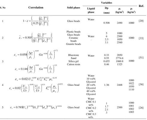
Estimation of the solid holdup in LSCFB under different systems and operating conditions proposed by several authors are reported in Table 2.
Table 2.Estimation of solid holdup in LSCFB for different systems proposed by several authors.
S. No Correlation Solid phase
Variables Ref. Liquid phase Dp (mm) ρs
(kg/m3)
ρl
(kg/m3)
1
0.8
8 . 0 25 . 0 1 l s U G
Glass beads Water
0.508 2490 1000 [20]
2
0.53 0.37
17 . 0 505 . 0 p l s s d U G Plastic beads Glass beads Ceramic beads Granite beads Water . 5 6 2.3 3.1 1080 2500 1850 2560
1000 [33]
3 72 . 0 06 . 0 05 . 0 058 .
0
f a l s j j Ga 25 . 1 06 . 0 05 . 0 146 . 0 l a l s j j Ga Bluestone Sand Silica gel Cation resin
Water 0.33 0.55 0.655 0.46 2850 2774.6 1060.8 1325 1000 [51] 4 19 . 0 1 51 . 0 31 . 0 12 99 . 0 11 s 0.02
U U Lo
055 . 0 1 51 . 0 31 . 0 12 99 . 0 11
s 0.02
w o L Ut U Ut U
Glass bead
Water 10 vol% Glycerol 20 vol% Glycerol 40 vol% Glycerol
1.36 2468
1000 1022 1050 1110
[36]
5 s 0.783
UL 0.100
Gs 0.164
dp 0.302
L 0.036 Glass beadFigure 2. The effect of viscosity on average solid holdup for resin-glycerol system [50].
7. Effect of density
The effect of the particle density on the solid circulation rate for the water system was studied by Natarajan [41], observed the flow behavior is similar for all particles of different density and same size and observed the critical transitional velocity for low-density particles is lower and solid circulation rate is higher for low-density particles and the maximum liquid velocity decreases for low-density particles. The decrease in density decreases the solid holdup with an increase in liquid velocity more rapidly. These results are consistent with the previous observation [51] for water system using silica gel and resin. For the given fluid with viscosity 1.36 cP for resin and sand of 0.5 mm, there is a considerable height of dense phase at the bottom of the test section for all operating conditions maintained in the test section. In the case of low dense particle resin, no dense phase was observed at the bottom of the test section. For heavy solid particles, the gravitational force is more predominant and the particles have to accelerate initially so as to reach the fully developed regime, since the contribution of drag is balanced by the gravitational component on the particles. As the density ratio is greater than 1 (ρs - ρl)/ρl >1, there exists a accelerating or dense regime at the bottom of the test section [33].
The information on the variation of solid velocity with change in different density for viscous solutions is limited in the literature. [38] noted that flow behavior is similar in increasing trends for both the solids (resin and sand) and the solid circulation rate for lower density particle (resin) is more than the higher density (sand) due to critical transition velocity which is less for low density particle than the higher density particle as lighter particle has lower terminal velocity resulting in early circulation of solids and the maximum liquid velocity decreases for lower density
particle. The maximum liquid velocity corresponding to maximum solid velocity is lower for low dense material and decreases with an increase in viscosity of the liquid. For the given auxiliary velocity solid input to the riser increases and the liquid velocity at which circulation starts is lower for lighter material and viscous system.
8. Conclusion
A brief review of the hydrodynamics studies in a liquid-solid circulating fluidized bed, its application and performance with regard to the effect of various operating parameters presented. Overall we observed that due to its homogeneous behaviour and independent solid handling in riser and downcomer the LSCFB would have wide industrial importance. A large number of publications has appeared on topics covering hydrodynamics and its modelling for different solid feeding system and for solids of different size and density using water as a fluid. But still limited work has been reported on hydrodynamics in a LSCFB using viscous fluids as well using a fluid of low viscosity. The effect of an increase in thw liquid viscosity in heat and mass transfer coefficient should be studied extensively in a LSCFB as the industrial processing fluids are highly viscous.
References
[1] Richardson, J. F., & Zaki, W. N. (1954). The sedimentation of a suspension of uniform spheres under conditions of viscous flow. Chemical Engineering Science, 3(2), 65-73.
[2] Zhu, J. X., Karamanev, D. G., Bassi, A. S., & Zheng, Y. (2000). (Gas‐) liquid‐solid circulating fluidized beds and their potential applications to bioreactor engineering. The Canadian Journal of
Chemical Engineering, 78(1), 82-94.
[3] Liang, W., Yu, Z., Jin, Y., Wang, Z., Wang, Y., He, M., & Min, E. (1995). Synthesis of linear alkylbenzene in a liquid–solid circulating fluidized bed reactor. Journal of Chemical Technology & Biotechnology:
International Research in Process,
Environmental AND Clean
Technology, 62(1), 98-102.
[4] Lan, Q., Bassi, A., Zhu, J. X., & Margaritis, A. (2002). Continuous protein recovery from whey using liquid‐solid circulating fluidized bed ion‐exchange extraction. Biotechnology and
bioengineering, 78(2), 157-163.
fluidized‐bed ion exchanger. AIChE
journal, 48(2), 252-261.
[6] Feng, X., Jing, S., Wu, Q., Chen, J., & Song, C. (2003). The hydrodynamic behavior of the liquid–solid circulating fluidized bed ion exchange system for cesium removal. Powder
technology, 134(3), 235-242.
[7] Cui, Y., Nakhla, G., Zhu, J., & Patel, A. (2004). Simultaneous carbon and nitrogen removal in anoxic-aerobic circulating fluidized bed biological reactor (CFBBR). Environmental
technology, 25(6), 699-712.
[8] Patel, A., Zhu, J., & Nakhla, G. (2006). Simultaneous carbon, nitrogen and phosphorous removal from municipal wastewater in a circulating fluidized bed bioreactor. Chemosphere, 65(7), 1103-1112.
[9] Trivedi, U.J., A. S. Bassi and J. Zhu. Liquid-Solid Circulating Fluidized Beds: An Attractive Immobilized Bioreactor System to Treat Phenolic Pollutants, . in 8th international Conference on Circulating Fluidized Beds. 2005. International Academic Publishers and World Publishing Corporation, China.
[10] Trivedi, U., Bassi, A., & Zhu, J. X. J. (2006). Continuous enzymatic polymerization of phenol in a liquid–solid circulating fluidized bed. Powder
technology, 169(2), 61-70.
[11] Patel, M., Bassi, A. S., Zhu, J. J. X., & Gomaa, H. (2008). Investigation of a dual‐
particle liquid–solid circulating fluidized bed bioreactor for extractive fermentation of lactic acid. Biotechnology
progress, 24(4), 821-831.
[12] Ilamathi, R., Nirmala, G. S., & Muruganandam, L. (2014). Heavy metals biosorption in liquid solid fluidized bed by immobilized consortia in alginate beads. International Journal of ChemTech Research, 6, 652-662.
[13] Chen, Y. M., Jang, C. S., Cai, P., & Fan, L. S. (1991). On the formation and disintegration of particle clusters in a liquid-solid transport bed. Chemical
engineering science, 46(9), 2253-2268.
[14] Liang, W. G., Zhu, J. X., Jin, Y., Yu, Z. Q., Wang, Z. W., & Zhou, J. (1996). Radial nonuniformity of flow structure in a liquid-solid circulating fluidized bed. Chemical
Engineering Science, 51(10), 2001-2010.
[15] Liang, W. G., & Zhu, J. X. (1997). A core-annulus model for the radial flow structure in a liquid-solid circulating fluidized bed (LSCFB). Chemical Engineering Journal, 68(1), 51-62.
[16] Liang, W., Zhang, S., Zhu, J. X., Jin, Y., Yu, Z., & Wang, Z. (1997). Flow characteristics of the liquid–solid circulating fluidized bed. Powder Technology, 90(2), 95-102.
[17] Liang, W. G., & Zhu, J. X. (1997). Effect of Radial Flow Nonuniformity on the Alkylation Reaction in a Liquid− Solid Circulating Fluidized Bed (LSCFB) Reactor. Industrial & engineering
chemistry research, 36(11), 4651-4658.
[18] Kuramoto, K., Tanaka, K., Tsutsumi, A., Yoshida, K., & Chiba, T. (1998). Macroscopic flow structure of solid particles in circulating liquid-solid fluidized bed riser. Journal of chemical
engineering of Japan, 31(2), 258-265.
[19] Zheng, Y., Zhu, J. X., Wen, J., Martin, S. A., Bassi, A. S., & Margaritis, A. (1999). The axial hydrodynamic behavior in a liquid‐solid circulating fluidized bed. The
Canadian Journal of Chemical
Engineering, 77(2), 284-290.
[20] Zheng, Y., & Zhu, J. X. J. (2000). Overall pressure balance and system stability in a liquid–solid circulating fluidized bed. Chemical Engineering Journal, 79(2), 145-153.
[21] Gibilaro, L. G., Di Felice, R., & Foscolo, P. U. (1988). A circulating liquid fluidised bed. Chemical engineering science, 43(10), 2901-2903.
[22] Liang, W., Yu, Z., Jin, Y., Wang, Z., & Wu, Q. (1995). The phase holdups in a gas-liquid-solid circulating fluidized bed. The Chemical Engineering Journal and The
Biochemical Engineering Journal, 58(3),
259-264.
[23] Zheng, Y., & Zhu, J. X. J. (2001). The onset velocity of a liquid–solid circulating fluidized bed. Powder technology, 114 (1-3), 244-251.
[24] Zheng, Y., Zhu, J. X., Marwaha, N. S., & Bassi, A. S. (2002). Radial solids flow structure in a liquid–solids circulating fluidized bed. Chemical Engineering
Journal, 88(1-3), 141-150.
fluidized bed. The Canadian Journal of
Chemical Engineering, 78(1), 75-81.
[26] Cho, Y. J., Song, P. S., Lee, C. G., Kang, Y., Kim, S. D., & Fan, L. T. (2005). Liquid radial dispersion in liquid-solid circulating fluidized beds with viscous liquid medium. Chem. Eng. Comm., 192(3), 257-271.
[27] Liang, W., Wu, Q., Yu, Z., Jin, Y., & Wang, Z. (1995). Hydrodynamics of a gas‐
liquid‐solid three phase circulating fluidized bed. The Canadian Journal of
Chemical Engineering, 73(5), 656-661.
[28] Yang, W., Wang, J., Zhou, L., & Jin, Y. (1999). Gas–liquid mass transfer behavior in three-phase CFB reactors. Chemical
engineering science, 54(22), 5523-5528.
[29] Yang, W. G., Wang, J. F., Chen, W., & Jin, Y. (1999). Liquid-phase flow structure and backmixing characteristics of gas–liquid– solid three-phase circulating fluidized bed. Chemical engineering science, 54(21), 5293-5298.
[30] Zhu, J. X., & Manyele, S. V. (2001). Radial nonuniformity index (RNI) in fluidized beds and other multiphase flow systems. The Canadian Journal of
Chemical Engineering, 79(2), 203-213.
[31] Zheng, Y., & Zhu, J. (2003). Radial distribution of liquid velocity in a liquid-solids circulating fluidized bed. International Journal of Chemical
Reactor Engineering, 1(1).
[32] Rao, V. B., Sailu, C., & Sandilya, D. K. (2007). An experimental study of liquid-particle flow in circulating fluidized bed. Chemical Engineering
Communications, 194(3), 353-367.
[33] Rao, V. B., Santhosha, W. S & Bala Narsaiah
T (2007), Modelling of Flow Structure Near the Wall in Circulating Fluidised Bed, Indian
Chemical Engineer, 49(1), 38-44.
[34] Vidyasagar, S., Krishnaiah, K., & Sai, P. S. T. (2008). Hydrodynamics of a liquid–solid circulating fluidized bed: Effect of dynamic leak. Chemical Engineering
Journal, 138(1-3), 425-435.
[35] Shilapuram, V., Krishnaiah, K., & Sai, P. S. T. (2009). Comparison of macroscopic flow properties obtained by three methods of operation in a liquid–solid circulating fluidized bed. Chemical Engineering and
Processing: Process Intensification, 48(1),
259-267.
[36] Vidyasagar, S., Krishnaiah, K., & Sai, P. S. T. (2011). Macroscopic properties of
liquid–solid circulating fluidized bed with viscous liquid medium. Chemical
Engineering and Processing: Process
Intensification, 50(1), 42-52.
[37] Sang, L., & Zhu, J. (2012). Experimental investigation of the effects of particle properties on solids holdup in an LSCFB riser. Chemical engineering journal, 197, 322-329.
[38] Nirmala, G., Muruganandam, L., & Kumar, P. (2014). Viscosity Effects on Solid Circulation Rate in a Liquid Solid Circulating Fluidized Bed. Journal of
Applied Sciences, 14(10), 1037-1042.
[39] Nirmala, G. S., & Muruganandam, L. (2013). Hydrodynamics Studies in a Liquid Solid Circulating Fluidized Bed of Varying Liquid Viscosity. Journal of The Institution of Engineers (India): Series E, 94(2), 73-78.
[40] Nirmala, G., Muruganandam, L., & Kumar, P. (2014). Solid holdup in liquid solid circulating fluidized bed with viscous liquid medium. Alexandria Engineering
Journal, 53(4), 959-968.Engineering
Journal, 2014. 53(4): p. 959-968.
[41] Natarajan, P., Velraj, R., & Seeniraj, R. V. (2008). Effect of various parameters on the solid circulation rate in a liquid–solid circulating fluidized bed. Asia‐Pacific
Journal of Chemical Engineering, 3(4),
459-470.
[42] Palani, N., Ramalingam, V., Ramadoss, G., & Seeniraj, R. V. (2011). Study of slip velocity and application of drift-flux model to slip velocity in a liquid–solid circulating fluidized bed. Advanced Powder
Technology, 22(1), 77-85.
[43] Zheng, Y. I. N. G. (2004). Radial Particle Profiles in a Liquid‐Solid CFB with Varying Viscosity. Chemical Engineering
& Technology: Industrial Chemistry‐Plant
Equipment‐Process Engineering‐
Biotechnology, 27(7), 769-776.
[44] Roy, S., & Dudukovic, M. P. (2001). Flow mapping and modeling of liquid− solid risers. Industrial & engineering chemistry
research, 40(23), 5440-5454.
[45] Roy, S., Chen, J., Kumar, S. B., Al-Dahhan, M. H., & Duduković, M. P. (1997). Tomographic and Particle Tracking Studies in a Liquid− Solid Riser. Industrial & engineering chemistry research, 36(11), 4666-4669.
Hydrodynamics in Liquid‐Solid Circulating Fluidized Beds. The Canadian Journal of
Chemical Engineering, 83(2), 177-185.
[47] Roy, S., Sai, P. S. T., & Jayanti, S. (2014). Numerical simulation of the hydrodynamics of a liquid solid circulating fluidized bed. Powder technology, 251, 61-70.
[48] Kalaga, D. V., Reddy, R. K., Joshi, J. B., Dalvi, S. V., & Nandkumar, K. (2012). Liquid phase axial mixing in solid–liquid circulating multistage fluidized bed: CFD
modeling and RTD
measurements. Chemical Engineering
Journal, 191, 475-490.
[49] Shin, K. S., Song, P. S., Lee, C. G., Kang, S. H., Kang, Y., Kim, S. D., & Kim, S. J. (2005). Heat‐transfer coefficient in viscous liquid–solid circulating fluidized beds. AIChE journal, 51(2), 671-677.
[50] Nirmala, G., Muruganandam, L., & Kumar, P. (2015). Solid holdup and circulation rate in a liquid-solid circulating fluidized bed with viscous liquid medium. Brazilian
Journal of Chemical Engineering, 32(4),
849-856.
[51] Palani, N., Ramalingam, V., & Seeniraj, R. V. (2008). Effect of various parameters on the solids holdup in a liquid-solid circulating fluidized bed. International
Journal of Chemical Reactor
Engineering, 6(1).
[52] Roy, S., Kemoun, A., Al‐Dahhan, M. H., & Dudukovic, M. P. (2005). Experimental investigation of the hydrodynamics in a liquid–solid riser. AIChE journal, 51(3), 802-835.
![Figure 2. The effect of viscosity on average solid holdup for resin-glycerol system [50]](https://thumb-us.123doks.com/thumbv2/123dok_us/8459456.1707918/13.595.44.294.69.263/figure-effect-viscosity-average-solid-holdup-resin-glycerol.webp)
