*Corresponding author’s e-mail: nmasri@upm.edu.my
Stress Intensity Factor for a Thermally Insulated
Crack in Bonded Dissimilar Materials
K.B. Hamzah1,4, N.M.A. Nik Long 1,2*, N. Senu1,2 and Z.K. Eshkuvatov3
1Laboratory of Computational Sciences and Mathematical Physics, Institute for Mathematical Research, Universiti Putra Malaysia, 43400 Serdang, Selangor, Malaysia
2Mathematics Department, Faculty of Science, Universiti Putra Malaysia, 43400 Serdang, Selangor, Malaysia 3Faculty of Science and Technology, Universiti Sains Islam Malaysia, 71800 Negeri Sembilan, Malaysia 4Fakulti Teknologi Kejuruteraan Mekanikal dan Pembuatan, Universiti Teknikal Malaysia Melaka, Hang Tuah Jaya,
76100 Durian Tunggal, Melaka, Malaysia
The modified complex variable function method with the continuity conditions of the resultant force, displacement and heat conduction functions are used to formulate the hypersingular integral equation (HSIE) for a thermally insulated circular arc crack or a thermally insulated inclined crack in the upper part of bonded dissimilar materials subjected to remote stress. The HSIE is solved numerically for the unknown crack opening displacement function and the known traction along the crack as the right hand term using the appropriate quadrature formulas. Numerical results showed the behavior of the nondimensional stress intensity factor (SIF) at all crack tips. The nondimensional SIF depends on the crack geometries, the distance between crack and the boundary, the elastic constants ratio, the heat conductivity ratio and the thermal expansion coefficients ratio.
Keywords: stress intensity factor; thermally insulated crack; bonded dissimilar materials; modified complex variable; hypersingular integral equation
I. INTRODUCTION
The strength and life cycles of the engineering structure can be effected by emergence of the crack and this situation makes more worsen when the structures are exposed to the thermal. This phenomenon has interested many researchers to investigate the behaviour of stress intensity factors (SIF), which control the stability behaviour of bodies or materials containing cracks or flaws, for the thermoelastic crack problems in an infinite plane (Chen & Hasebe, 2003; Zhong
et al., 2018), half plane (Jin & Noda, 1993; Li et al., 2015) and bonded dissimilar materials (Chao & Shen, 1995; Shevchuk, 2017; Mishra & Das, 2018; Zhou & Kim, 2016; Choi, 2016; Ding & Li, 2015) subjected to remote stress.
The singular integral equations was derived and solved numerically by using the appropriate interpolation formulas for two dimensional thermoelastic crack problems in bonded dissimilar materials (Chao & Shen, 1995). The nondimensional SIF for an undercoat crack perpendicular to
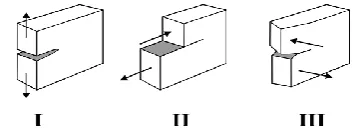
99 Figure 1. Three types of modes in fracture mechanics
There are three types of modes in fracture mechanics such as tensile opening (Mode I), in plane shear (Mode II) and out of plane tearing (Mode III) as shows in Figure 1 (Shields et al., 1992). The Mode I corresponds to normal separation of the crack faces under the action of tensile stresses. The Mode II is the shear stress acting parallel to the crack faces and perpendicular to the crack front. Whereas the Mode III is a shear stress acting parallel to the crack faces and parallel to the crack front.
The aim of this paper is to investigate the behavior of nondimensional SIF for a thermally insulated circular arc crack or a thermally insulated inclined crack in the upper part of bonded dissimilar materials subjected to the remote shear stress
1 2
x x p
= = .
II. MATHEMATICAL FORMULATION
The complex potentials for heat conduction problem introduced by Muskhelishvili (1953) is expressed as
( )
z T x y( )
, iQ x y( )
, = + (1)
where T x y
( )
, =Re( )
z is temperature distribution,( )
, Im( )
Q x y = −k z is resultant heat flux function and k stands for the heat conductivity. Generally the stress components
(
x, y, xy)
, the resultant force function (X, Y), and the displacements (u, v) for thermally insulated crack in an infinite plane are expressed in terms of three complex potential functions ( )
z , ( )
z and ( )
z as follows( )
( )
2 2 " '
y x i xy z z z
− + = + (2)
( )
'( )
( )
f = − +Y iX= z =z z + z (3)
(
)
( )
( )
( ) (
)
( )
2G u+iv = z −z' z − z + +1 G
z dz (4) where z= +x iy denotes complex variable, G is shear modulus of elasticity, = −3 4v and =(
(
1+v)
)
(
2 1(
−v)
)
for plane strain, = −(
3 v) (
1+v)
and = +(
1 v)
2 forplane stress, v is Poisson's ratio and is the thermal expansion coefficient. A derivative in a specified direction of Eqn. (3)with respect to z, yields the normal (N) and tangential (T) components of traction along the segment
,
z z+dz, which is defined as follows
'( )
'( )
"( )
'( )
.d d z
f z z z z z N iT
dz dz
= + + + = +
(5)
According to Nik Long and Eshkuvatov (2009) and Chen et al. (2003), complex potentials for the crack L in an infinite thermoelastic modeled by the distribution of crack opening displacement (COD) function, g t
( )
, and the temperature jump along the crack faces, ( )
t , can be expressed as( )
( )
1
1 2
p
L
g t dt z
t z
=
−
(6)( )
( )
(
)
1 2
1 1
2 2
p L L
g t dt dt tdt
g t
t z t z t z
= + −
− − −
(7)( )
( )
1 1
p L
t dt z
i t z
=
−
(8)where g t
( )
is defined by( ) ( ) ( ) ( )
2(
)
(
( )
( )
)
, 1
G
g t u t iv t u t iv t t L
i
+ −
= + − +
+ (9)
( )
( )
(
u t +iv t)
+ and(
u t( )
+iv t( )
)
− denote the displacements at point t of the upper and lower crack faces, respectively. Substituting Eqns. (4), (6), (7) and (8) into dislocation distribution g t'( )
, yields( )
( )
( )
' 2
g t =g t − i t . (10) The single-valuedness condition for the displacement
( )
' 0
Lg t dt=
. (11)Apply Eqn. (11) into (10), yields
( )
( )
2
L L
i
t dt g t dt
− =
. (12)Substituting Eqn. (12) into (8) to represent the complex potential of the temperature jump in terms of COD as
( )
( )
1
1 2
p
L
g t dt z
t z
= −
−
. (13)The condition for the stress components in the upper,
1
x
, and lower parts,
2
x
100 1 2 1 2 1 2 1 1 x x x x E E = = (14)
where E1=2G1
(
1+v1)
and E2=2G2(
1+v2)
are Young's modulus of elasticity for upper and lower parts of bonded dissimilar materials, respectively.The modified complex potentials (MCP) for the crack in the upper part of bonded dissimilar materials involve the principal parts
(
1p( )
z ,1p( )
z ,1p( )
z)
and the complementary parts(
1c( ) ( )
z ,1c z ,1c( )
z)
of the complex potentials defined as( )
( )
( )
1 z 1p z 1c z
= + (15)
( )
( )
( )
1 z 1p z 1c z
= + (16)
( )
( )
( )
1 z 1p z 1c z .
= + (17)
Whereas, for a crack in the lower part, the complex potentials are represented by 2
( )
z , 2( )
z and 2( )
z . The principal parts of complex potentials are referred to the complex potentials for the thermally insulated cracks in an infinite plane.Since the temperature and resultant heat flux are continuous across the boundary, the heat conduction problem (1), yields
( )
( )
( )
( )
1 t 1 t 2 t 2 t ,t L
+ −
+ = +
(18)
( )
( )
( )
( )
1 1 1 2 2 2 ,
k t t k t t t L
+ −
+ = +
(19)
Applying Eqn. (15) into Eqns. (18) and (19), the following expressions are obtained
( )
( )
( )
( )
1 2
1 1 1
1 2
1
2 1 2
1 2
, ,
2
, ,
c p b
p b
k k
z z z S L
k k
k
z z z S L
k k − = + + = + + (20)
where 1p
( )
z =1p( )
z , Lb is boundary of bonded dissimilarmaterials, S1 and S2 are upper and lower parts of bonded
dissimilar materials, respectively. Whereas the continuity conditions for resultant force (3) and displacement (4) are defined as
( )
( )
( )
( )
( )
( )
1 t t 1' t 1 t 2 t t 2' t 2 t ,
+ −
+ + = + +
(21)
( )
( )
( ) (
)
( )
( )
( )
( ) (
)
( )
2 1 1 1 1 1 1 1 1
1 2 2 2 2 2 2 2 2
' 1
' 1
G t t t t G t dt
G t t t t G t dt
+ + − − + + = − − + +
(22)where tL. Applying Eqns. (15), (16), (17) and (20) into Eqns. (21) and (22), the following expressions are obtained
( )
( )
( )
(
)
2( )
1
2 1
1 1 1
1 1
1 1 2 1 2 1
1 1
1 1 2 1 2
'
1
,
c p p
p b
L
G G
z z z z
G G
G G k k
z dz z S L
G G k k
− = + + + − + + + +
(23)( )
( )
( )
(
)
( )
(
)
( )
1 21 2 2 1
1 1 1
2 2 1
1 2
1 1 1
2 2 1
2 1 2
1 1 1 2 ' 1 2 1 ,
c p c
p L
p b
L
G G
z z z z
G G
G G
z dz
G G
k
z dz z S L
k k − = − + + + + + − + +
(24)( ) (
)
( )
(
)
( )
(
)
( )
1 2 1 2 2 12 2 1
1 2
1 1 1
2 2 1
2 1 2
1 2 1 2 1 1 2 1 , p p L p b L G z z G G G G z dz G G k
z dz z S L
k k + = + + + + + − + +
(25)( ) (
)
( )
( )
( )
(
)
( )
1 1 22 1 1 2
1 1 2
1 1 2 1 2 1
1 2
1 1 2 1 2
1 ' ' 1 , . p p p b L G
z z z z z z
G G
G G k k
z dz z S L
G G k k
+ = + − + + − + + + +
(26)The principal part of the traction for a thermally insulated crack in the upper part of bonded dissimilar materials can be obtained by substituting Eqns. (6) and (7) into (5) and letting point z approaches t0 on the crack.
Changing d z dz into dt0 dt0, yields
( )
( )
( )
(
)
( ) ( )
( ) ( )
0 0 1 2 1 0
0 2 0 1 1 , 2 1 , 2
p L L
L
g t dt
N t iT t A t t g t dt
t t
A t t g t dt
+ = + − +
(27) where( )
(
)
( )
( )
( )
( )
(
)
01 0 2 2
0
0 0
0 0 0
2 0 3 3
0 0 0 0 1 1 , , 2 1 ,
d t d t A t t
dt dt
t t t t
t t
d t d t d t d t
A t t
dt dt dt dt
t t t t
= − + − − − = + − − −
101
( )
( )
( ) ( )
( ) ( )
0 0 1 1 0
2 0 1 , 2 1 , 2 c L L
N t iT t D t t g t dt
D t t g t dt
+ = +
(28)( )
( )
( )
( )
( ) ( )
(
)
( )
( )(
( )
)
( )
( )
(
)
( )
0 2 11 0 2 3 2 2
1 1 2 0 0 0
0
0 0 0
0 0
0
3 3 2 2
0 0 0 0 0
0 0 1 2 2 1 0
3
2 2 1 0
0
2
1 1 1
,
2 2 3 6 1 1
2 1
t t
G G d t
D t t
G G t t t t t t t t dt
t t t t t t t
d t d t
dt t t t t t t dt t t
t t G G d t
G G dt
t t − − = + + + + − − − − − + − − + − − − − − − − − − + + + −
( )
(
)
( )
(
)
(
)
2 0 0 01 1 2 1 2 1 0
2
0 0
1 1 1 2 1 2 0 0
0 1 1 2 1 2
1 2
0 0
2 2 1 0 1 2
1
1 1 1
1 2 1 1
t t
G G k k d t t t
G G k k t t dt t t t t
k G G d t
G G dt t t k k t t
− + − − − + + − − − + − + + + − + − + −
( )
( ) ( ) ( )
( )
(
)
( )
( )
(
)
(
)
( )
0 2 12 0 2 2 2 3
1 1 2 0
0 0 0
0 0
0 1 1 2 1 2 1
2 2
0 0 0 1 1 2 1 2 1 0
2
1 1 1
,
2 1
1 1 1
t t
G G d t
D t t
G G t t t t t t t t dt
t t G G
d t k k d t
dt t t t t G G k k t t dt
− − = + + + + − − − − − + − − − + + + − − −
Summing Eqns. (27) and (28) yields the following HSIEs for a thermally insulated crack in the upper part of bonded dissimilar materials
( )
( )
( )
( )
( )
( )
( )
(
)
( )
( )
( )
( )
0 0 1 0 0 1 0 0 1
1 0 2 0
2 0
1 1 1
, ,
2 2
p c
L L L
N t iT t N t iT t N t iT t
g t dt
E t t g t dt E t t g t dt t t
+ = + + +
= + +
−
(29)where
( )
( )
( )
( )
( )
( )
1 ,0 1 ,0 1 ,0 , 2 ,0 2 ,0 2 ,0 .
E t t =A t t +D t t E t t =A t t +D t t
Note that the first integral in Eqn. (29) with the equal sign represent the hypersingular integral and must be defined as a finite part integral (Nik Long & Eshkuvatov, 2009). If k2=0
and G2=0 the Eqn. (29) reduce to the equation for a crack in half plane elasticity (Chen et al., 2009). If k1=k2, 1=2
and G1=G2 the Eqn. (29) reduce to the equation for a crack in an infinite plane (Rafar et al., 2017).
For solving the HSIEs (29), the function g t
( )
is mapped on a real axis s with an interval 2a as follows( )
( ) 2 2( )
,t t s
g t = = a −s H s (30)
where H s
( )
=H s1( )
+iH2( )
s . Then we apply the quadrature formulas introduced by Mayrhofer and Fischer (1992).III. NUMERICAL RESULTS
Stress intensity factor (SIF) at the crack tips Aj is defined
as
(
1 2)
2 lim '( )
j j j j
A j
A A A A
t t
K K iK t t g t a F
→
= − = − = (31)
where j=1, 2 and 1 2
j j j
A A A
F =F +iF is the
nondimensional SIF at cracks tips Aj. Note that in the
sequel we denote G G2 1 the elastic constants ratio, k2 k1 heat conductivity ratio and 2 1 thermal expansion coefficients ratio. Whereas for comparison purposes, we use k2 k1=5.0 and =2 1 1.0 for crack with thermal,
1 2 0.0
k =k = and 1=2=0.0 for crack without thermal,
and elastic constant ratio is G G2 1=2.0.
(a)
(b)
102 Consider a thermally insulated circular arc crack facing to the left (Figure 2(a)) and a thermally insulated inclined crack (Figure 2(b)) in the upper part of bonded dissimilar materials subjected to remote stress
1 2
x x p = = .
Table 1 displays the nondimensional SIF for the problem defined in Figure 2(a) when h=2R, G G2 1=1.0, k2 k1=1.0,
2 1 1.0
= and
varies. It is observed that F1 at cracktip A1 is equal to F1 at crack tip A2, whereas F2 at crack tip
A1 is equal to the negative of F2 at crack tip A2. Our results
are good agreement with those of Chen and Hasebe (2003).
Table 1. SIF for a thermally insulated circular arc crack when h=2R, G G2 1=1.0, k2 k1=1.0, =2 1 1.0 and
variesSIF
100 200 300 400 500 600 700 800 900
F1A1* 0.9735 0.8970 0.7783 0.6278 0.4583 0.2823 0.1115 -0.0441 -0.1764
F1A1** 0.9736 0.8970 0.7779 0.6272 0.4575 0.2815 0.1107 -0.0447 -0.1768
F2A1* 01727 0.3317 0.4672 0.5704 0.6362 0.6630 0.6516 0.6057 0.5306
F2A1** 01723 0.3318 0.4673 0.5703 0.6359 0.6625 0.6511 0.6053 0.5303
* Current study
** (Chen & Hasebe, 2003)
(a)
(b)
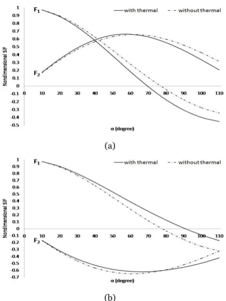
Figure 3. Comparison of the nondimensional SIF with and without thermal when h=2R and varies (Figure 2(a))
Figure 3 shows the comparison between the nondimensional SIF at crack tips A1 and A2 with and
without thermal when h=2R and varies for the problem defined in Figure 2(a). It is found that at crack tip A1, F1 and
F2 for the crack without thermal is higher than F1 and F2 for
the crack with thermal. While at crack tip A2, F1 for the
crack without thermal is lower than F1 for the crack with
thermal, however F2 for the crack without thermal is higher
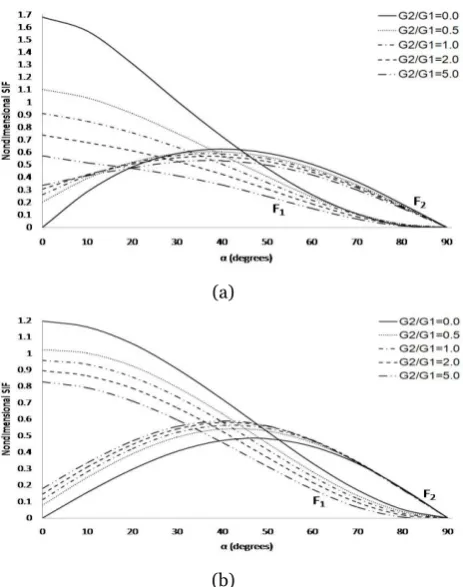
than F2 for the crack with thermal for 80o. For different values of G G2 1 when =2 1 0.5, k2 k1=2.0, h=2R and
varies the nondimensional SIF at crack tips A1 and A2 are
presented in Figure 4. It is found that at crack tip A1, as
increases F1 decreases and F2 decreases for 60o, and as
2 1
G G increases F1 and F2 decrease. Whereas at crack tip
A2, as increases F1 decreases and F2 decreases for
60o
, and as G G2 1 increases F1 increases and F2
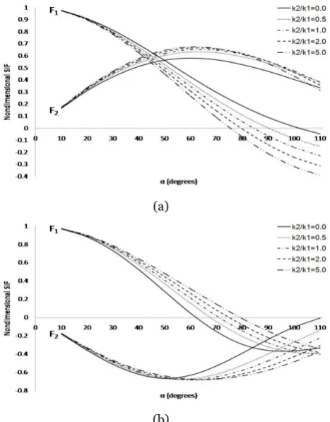
increases for 90o. For different values of k2 k1 when
2 1 0.5
G G = , =2 1 2.0 , h=2R and varies the nondimensional SIF at crack tips A1 and A2 are presented in
Figure 5. It is observed that at crack tip A1, as increases
F1 decreases and F2 decreases for 60o, and as k2 k1 increases F1 decreases and F2 increases. Whereas at crack
tip A2, as increases F1 decreases and F2 decreases for
50o
, and as k2 k1 increases F1 increases and F2
decreases for 50o. For different values of 2 1 when
2 1 0.5
k k = , G G2 1=2.0 , h=2R and varies the nondimensional SIF at crack tips A1 and A2 are presented in
Figure 6. It is found that at crack tip A1, as increases F1
103
2 1 5.0
= and for other values of 2 1 F2 increases
when 60o, and as 2 1 increases F1 increases and F2
decreases. Whereas at crack tip A2, for =2 1 5.0 F1
increases when 60o and F2 increases when 30o, for other values of 2 1 F1 decreases as increases and F2
decreases for 50o, and as 2 1 increases F1 decreases
and F2 increases.
Figure 7 presents the comparison between the nondimensional SIF at all crack tips in bonded dissimilar materials with and without thermal when R h=0.9 and
varies for the problem defined in Figure 2(b). It is observed that F1 for the crack without thermal is higher than F1 for
the crack with thermal at all crack tips, while F2 for the
crack without thermal is lower than F2 for the crack with
thermal.
(a)
(b)
Figure 4. Nondimensional SIF for different values of
2 1
G G when =2 1 0.5, k2 k1=2.0, h=2R and varies (Figure 2(a))
(a)
(b)
Figure 5. Nondimensional SIF for different values of
2 1
k k when G G2 1=0.5, =2 1 2.0, h=2R and varies (Figure 2(a))
(a)
(b)
Figure 6. Nondimensional SIF for different values of
2 1
104 (a)
(b)
Figure 7. Comparison of the nondimensional SIF with and without thermal versus when R h=0.9 (Figure 2(b))
(a)
(b)
Figure 8. Nondimensional SIF for different values of
2 1
G G when =2 1 0.5, k2 k1=2.0, R h=0.9 and
varies (Figure 2(b))
(a)
(b)
Figure 9. Nondimensional SIF for different values of 2 1
k k when G G2 1=0.5, =2 1 2.0, R h=0.9 and
varies (Figure 2(b))
Figure 8 presents the nondimensional SIF for different values of G G2 1 when =2 1 0.5, k2 k1=2.0, R h=0.9 and varies (Figure 2(b)). It is found that at crack tip A1,
as increases F1 decreases and F2 decreases for 45o, and as G G2 1 increases F1 decreases and F2 decreases for
25o
. Whereas at crack tip A2, F1 behaves as F1 at crack
tip A1, while F2 increases for 45o and as G G2 1 increases. Figure 9 presents the nondimensional SIF for different values of k2 k1 when G G2 1=0.5, =2 1 2.0,
0.9
R h= and varies (Figure 2(b)). It is found that F1
decreases for 20o and F2 increases for 50o at all crack tips. Whereas F1 and F2 increase at all crack tips as
2 1
G G increases.
IV. CONCLUSION
105 The HSIE reduces to a crack problem in a half plane when
2 0
k = and G2=0, and for k1=k2, 1=2 and G1=G2 the HSIE reduce to a crack problem in an infinite plane. The Mode I and Mode II nondimensional SIF at the crack tips depends on the elastic constant ratio G G2 1 , heat conductivity ratio k2 k1 , thermal expansion coefficients ratio 2 1 and cracks geometries. The nondimensional SIF at crack tips for a crack without thermal is higher than nondimensional SIF for a crack with thermal, however the position and crack geometries play an important role to the
behaviour of nondimensional SIF.
V. ACKNOWLEDGEMENT
The first author would like to thank to the Ministry of Education Malaysia, Universiti Putra Malaysia and Universiti Teknikal Malaysia Melaka for the financial support. The second author would like to thank the Universiti Putra Malaysia for Putra Grant, project no: 9567900 and Fundamental Research Grant Scheme (FRGS) project no: 01-01-16-18685R5524975.
VI. REFEREENCES
Chao, CK & Shen, MH 1995, ‘Solutions of thermoelastic crack problems in bonded dissimilar media or half-plane medium’, International Journal of Solids Structures, vol. 32, no. 24, pp. 3537-3554.
Chen, YZ & Hasebe, N 2003, ‘Solution for a Curvilinear Crack in a Thermoelastic Medium’, Journal of Thermal Stresses, vol. 26, no. 3, pp. 245-259.
Chen, YZ, Hasebe, N & Lee, KY 2003, Multiple crack problems in elasticity, WIT Press, Southampton.
Chen, YZ, Lin, XY & Wang, XZ 2009, ‘Numerical solution for curved crack problem in elastic half-plane using hypersingular integral equation’, Philosophical Magazine, vol. 89, no. 26, pp. 2239-2253.
Choi, HJ 2016, ‘Analysis of Stress Intensity Factors for Edge Interfacial Cracks in Bonded Dissimilar Media with a Functionally Graded Interlayer under Antiplane Deformation’, Theoretical and Applied Fracture Mechanics, vol. 82, pp. 88-95.
Ding, SH & Li, X 2015, ‘Thermoelastic analysis of nonhomogeneous structural materials with an interface crack under uniform heat flow’, Applied Mathematics and Computation, vol. 271, pp. 22-33.
Jin, ZH & Noda, N 1993, ‘An internal crack parallel to the boundary of a nonhomogeneous half plane under thermal loading’, International Journal of Engineering Science, vol. 31, no. 5, pp. 793-806.
Li, W, Li, J, Abdelmoula, R, Song, F & Jiang, CP 2015, ‘Inertia effect analysis of a half-plane with an induced crack under thermal loading using hyperbolic heat conduction’, Journal of Applied Mathematics and Mechanics, pp. 1-17.
Mayrhofer, K & Fischer, FD 1992, ‘Derivation of a new analytical solution for a general two-dimensional finite-part integral applicable in fracture mechanics’, International Journal of Numerical Method in Engineering, vol. 33, no. 5, pp. 1027-1047.
Mishra, PK & Das, S 2018, ‘Two interfacial collinear griffith cracks in thermo-elastic composite media’, Thermal Science, vol. 22, no. 1B, pp. 423-433.
Muskhelishvili, NI 1953, Some basic problems of the mathematical theory of elasticity, Noordhoff International Publishing, Leyden.
Nik Long, NMA & Eshkuvatov ZK 2009, ‘Hypersingular integral equation for multiple curved cracks problem in plane elasticity’, International Journal of Solids and Structures, vol. 46, pp. 2611-2617.
Rafar, RA, Nik Long, NMA, Senu, N & Noda, NA 2017, ‘Stress intensity factor for multiple inclined or curved cracks problem in circular positions in plane elasticity’, Journal of Applied Mathematics and Mechanics, vol. 97, pp. 1482-1495.
Shevchuk, VA 2017, ‘Thermoelasticity problem for a multilayer coating/half-space assembly with undercoat crack subjected to convective thermal loading’, Journal of Thermal Stresses, vol. 40, no. 10, pp. 1215-1230.
Shields, EB, Srivatsan, TS & Padovan J 1992, ‘Analytical methods for evaluation of stress intensity factors and fatigue crack growth’, Engineering Fracture Mechanics, vol. 42, no. 1, pp. 1-26.
106 Zhou, YT & Kim, TW 2016, ‘Thermal resistance inside an