493 | P a g e
THE DESIGN OF POWER DC BUS SYSTEM TO INCREASE
THE SOLAR EFFICIENCY BY USING DC-DC CONVERTER
1
Miss. Bhagyashree N. Pikalmunde,
2Mr. Vinod Bhongade
1
Dept. of Electrical Engineering, Gondwana University,R.C.E.R.T, Chandrapur, Maharashtra, (India)
2
Associate Professor, Department of Electrical Engineering,R.C.E.R.T, Chandrapur,Maharashtra,(India)
ABSTRACT
Non conventional energy based on photovoltaic system with storage energy battery is necessary to load requirement
for supply to electric grid. Due to use of dc-ac convertor, the efficiency does not improve. The power conditioning is
done by a dc–dc converter and a dc–ac inverter stages to produce the desired ac source. This is also done even
when the load is of dc type, such as typical portable electronic devices that require ac adaptors to be powered from
the ac mains. The aim of this project is to propose a hybrid PV-battery-powered dc bus system, that eliminates the
dc–ac conversion stage, resulting in lower cost and improved overall energy conversion efficiency. A high-gain
hybrid boost fly back converter is introduced with higher voltage conversion ratio than conventional boost
convertor topology.
Keywords:
DC Bus System, Dc–Dc Converter, Hybrid Fly Back Boost Converter, Solar Cell, PV Power
System.
I. INTRODUCTION
494 | P a g e
and since it is dc in nature. For that PV panel is required. The PV panel varying wattages available from a few watts to several hundred watts per panel. A DC load center for hooking up the batteries, and charge controller, and PV panels. Note that AC is not handled by your DC load center.1.1. Buck Converters (DC-DC) structure
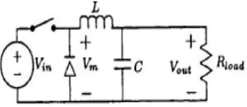
A buck converter (dc-dc) is shown in Fig. Only a switch is shown, for which a device as described earlier belonging to transistor family is used. Also a diode (termed as freewheeling) is used to allow the load current to flow through it, when the switch (i.e., a device) is turned off. The load is inductive (R-L) one. In some cases, a battery (or back emf) is connected in series with the load (inductive). Due to the load inductance, the load current must allowed path, which provided by diode. Otherwise, in absence of above diode, the high induced emf of the inductance, as load current tends to decrease, it may cause damage to switching device. If switching device used is thyristor, this circuit is called as a step-down chopper, as output voltage is normally lower than the input voltage. Similarly, this dc-dc converter is termed as buck one, due to reason given later one, due to reason given later.
Fig .1: Buck Converters (DC-DC)
II. AN OVERVIEW OF
PROPOSED WORK
A new approach to power generation using solar structure and DC-DC converter is presented. And which has higher efficiency and lower cost in compare to other methods of AC power generation. Initially, we investigate the effect of voltage on the efficiency of the system. And also calculate to the overall efficiency of the system.
In this project, both hardware and software setups are used. The hardware setup consists of PV panel, DC-DC converter, comparator, DC Bus, microcontroller, relay. With the help of hardware setup observe the output voltage and also observation of efficiency.
In the software setup, MATLAB software is used to understand the graphical nature of temperature by simulation. For that Embedded C programming is prefer to use.
The following steps to make a module:
495 | P a g e
4. Observe efficiency of the system.III. HARDWARE REQUIREMENT
DC-DC Converter
Microcontroller IC 89c51
Comparator
PV panel with Battery
Relay
Digital Multi-meter
3.1. DC-DC Converter
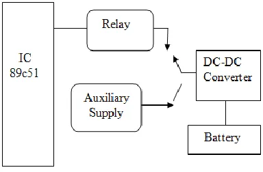
DC-DC Convertor is an electronic circuit which converts a source of direct current (DC) from one voltage level to another. DC to DC converters are important in portable electronic devices such as cellular phones, laptops computers, which are the supplied with power from batteries primarily. Such electronic devices often contain the several sub-circuits, each with its own voltage level requirement different from that supplied by the battery or an external supply (sometimes higher or lower than the supply voltage). Additionally, the battery voltage declines as its stored power is drained. Switched DC-DC converters offer a method to increase voltage from a partially lowered battery voltage thereby saving space instead of using multiple batteries to accomplish the same thing. Most DC-DC converters also regulate the output voltage. Some exceptions include high-efficiency LED power sources. In that paper the DC-DC Converter supply electricity to the battery with is connected to the relay as well as Auxiliary supply. As shown in the fig.
Fig. 2: Basic Structure of the System
3.2. Microcontroller IC 89C51
496 | P a g e
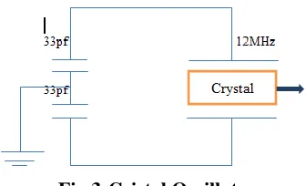
signal to the microcontroller IC 89c51. The IC also used to control the relay device for switching purpose. It consists of crystal oscillator device this device to generate the trigger signals of 12MHz.Fig.3:Cristal Oscillater
3.3. Comparator
In this paper, two comparator amplifier IC LM324 is used .The comparator amplifier IC LM324 which finally goes to battery and the second amplifier IC LM324 gives signal from auxiliary supply to the battery .This two comparator compares’ the signals from solar and auxiliary supply and gives the output.
Fig. 4: LM 324
3.4. PV panel with Battery
The Solar energy is the most readily available and free source of energy, since prehistorically times. Solar energy stored in the form of dc. This dc energy is converted into ac as per our load requirement. The solar panel receiving the sun rays and which generate 6volts dc which signals to provide amplifier. These amplifiers IC LM324 send the signal to the microcontroller.
497 | P a g e
The solar energy is used to generate the electrical signal and this electrical energy stored in the battery”.3.5. Relay
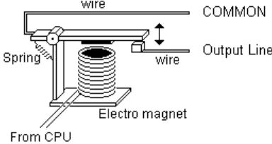
The Relay is used to reverse the supply to change the mode i.e. to switch form DC supply to the auxiliary supply. It is used for Domestic Appliances, Office Machines, Audio Equipment, Coffee-Pots, Control units, etc. Hear the relay is used to the purpose of activation of the switch. In this project the relay is used to control of the DC signals.
Fig. 6: Relay Circuit Diagram
3.6. Digital Multimeter
The digital millimeter reads the output from the battery .here the use of millimeter for to read the value of two signals one is from solar system and another is from auxiliary supply and compares both values with the help of tow comparator amplifiers IC LM324 and display the beneficial value of the system.
IV. WORKING OF THE MODEL
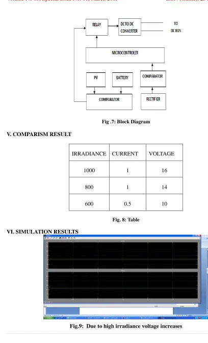
From block diagram it consists of different types of blocks like solar panel, comparators, microcontroller IC 89c51, relay, rectifier, DC-DC converter, battery. Firstly the solar panel receives sunlight to convert into electricity and these energy fed to the first comparator amplifier LM324.the comparator fed the signal to microcontroller IC 89c51.the IC69c51 take signal from comparator amplifier and fed to the relay device in the form of 1 signal at a constant voltage 6v.During the operation relay connected to the DC-DC converter with battery & the load gives the constant energy from battery device.
498 | P a g e
Fig .7: Block Diagram
V. COMPARISM RESULT
IRRADIANCE
CURRENT
VOLTAGE
1000
1
16
800
1
14
600
0.5
10
Fig. 8: Table
VI. SIMULATION RESULTS
499 | P a g e
(Irradiance = 1000,
Voltage = 16v, Current =1amp)
Fig.10: Due to high irradiance voltage decreases
(Irradiance = 800,
Voltage = 14v, Current =1amp)
Fig.11: Due to high irradiance voltage decreases
500 | P a g e
VII. RESULT
From hardware result and mat lab simulation result we observed that the due to used of DC-DC converter and a hybrid PV-battery-powered dc bus system, that eliminates the dc–ac conversion stage, resulting in lower cost and improved overall energy conversion efficiency.
VIII. CONCLUSION
We conclude that, when the load is of dc type, such as typical portable electronic devices that require ac adaptors to be powered from the ac mains. The aim of project is to propose a hybrid PV-battery-powered dc bus system that eliminates the dc–ac conversion stage, resulting in lower cost, improved overall energy conversion efficiency. A high-gain hybrid boost–fly back converter is, also introduced with several times higher voltage in higher dc bus levels and lower cable conduction losses.
REFERENCES
[1]. S.Y. Tsen, J. S .Kuo, S. W. Wang, and C .T .Hsieh, “Buck–boost combined with active clamp fly back converter for PV power system,” in Proc. IEEE Power Electron. Spec. Conf., 2007, pp. 138–144. [2]. Dylan Dah-Chuan Lu, Member, IEEE, and Vassilios G. Agelidis, Senior Member, IEEE.
“Photovoltaic-Battery-Powered DC Bus System for Common Portable Electronic Devices”.
[3]. L. Huber and M. M. Jovanovic, “A design approach for server power supplies for networking,” in Proc. IEEE-APEC’00 Conf., 2000, pp.1163–1169.
[4]. Battery Council International. Battery recycling [Online].
Available:http://www.batterycouncil.org/LeadAcidBatteries/BatteryRecycling/tabid/71/Default.aspx [5]. F. Blaabjerg, Z. Chen, and S. B. Kjaer, “Power electronics as efficient interface in dispersed power
generation systems,” IEEE Trans. Power Electron., vol. 19, no. 5, pp. 1184–1194, Sep. 2004. [6]. S. B. Kjaer, J. K. Pedersen, and F. Blaabjerg, “A review of single-phase grid-connected inverters for
photovoltaic modules,” IEEE Trans. Ind. Appl., vol. 41, no. 5, pp. 1292–1306, Sep./Oct. 2005.
[7]. F. Blaabjerg, R. Teodorescu, M. Liserre, and A. V. Timbus, “Overview of control and grid synchronization for distributed power generation systems,”IEEE Trans. Ind. Electron., vol. 53, no. 5, pp. 1398–1409,
Oct.2006.
[8]. J. Knight, S. Shirsavar, and W. Holderbaum, “An improved reliability Cuk based solar inverter with sliding mode control,” IEEE Trans. Power Electron., vol. 21, no. 4, pp. 1107–1115, Jul. 2006.
501 | P a g e
[10]. R. J. Wai, W. H. Wang, and C. Y. Lin, “High-performance stand-alone photovoltaic generationsystem,” IEEE Trans. Ind. Electron., vol. 5, no. 1, pp. 240–250, Jan. 2008.
[11]. S.Y.Tseng, J. S.Kuo, S.W.Wang, andC.T.Hsieh, “Buck–boost combined with active clamp flyback converter for PV power system,” in Proc. IEEE Power Electron. Spec. Conf., 2007, pp. 138–144.
[12]. Y. M. Chen and Y. C. Liu, “Development of multi-port converters for hybrid wind-photovoltaic power system,” in Proc. IEEE Region 10 Int. Conf. (TENCON), 2001, pp. 804–808.
[13]. Y.M. Chen, Y. C. Liu, F. Y.Wu, and Y. E.Wu, “Multi-input converter with power factor correction and maximum power point tracking features,” inProc. IEEE Appl. Power Electron. Conf., 2002, pp. 490– 496.
[14]. K. Kobayashi, H. Matsuo, and Y. Sekine, “An excellent operating point tracker of the solar-cell power supply system,” IEEE Trans. Ind. Electron., vol. 53, no. 2, pp. 495–499, Apr. 2006.
[15]. K. P. Yalamanchili and M. Ferdowsi, “Review of multiple input dc–dc converters for electric and hybrid vehicles,” in Proc. IEEE Veh. Power Propulsion Conf., 2005, pp. 552–559.
[16]. Y. M. Chen, Y. C. Liu, S. C. Hung, and C. S. Cheng, “Multi-input inverter for grid-connected hybrid PV/wind power system,” IEEE Trans. Power Electron., vol. 22, no. 3, pp. 1070–1077, May 2007.
[17]. T. F. Wu, C. H. Chang, and Y. J. Wu, “Single-stage converters for PV lighting systems with MPPT and energy backup,” IEEE Trans. Aerosp. Electron. Syst., vol. 35, no. 4, pp. 1306–1317, Oct. 1999. [18]. Q. Zhao and F. C. Lee, “High-efficiency, high step-up dc–dc converters,” IEEE Trans. Power Electron.
vol. 18, no. 1, pp. 65–73, Jan. 2003.
[19]. K. C. Tseng and T. J. Liang, “Novel high-efficiency step-up converter,” Proc. Inst. Electr. Eng. (IEE) Electr. Power Appl., vol. 151, pp. 182–190, 2004.