84 |
P a g e
ALGEBRAIC CODING THEORY IN THE QUEST FOR
EFFICIENT DIGITAL INDIA
Ajeet Singh
1, Shefali Kapoor
2 1,2Department of Mathematics, Lingaya’s University , Faridabad (India)
ABSTRACT
The objective of this paper is to demonstrate the application of Algebraic Coding towards achievement of
“Efficiency” of this huge Central Government Initiative.Digital India is a Government of India initiative with
the vision to transform economy of India using digital technologies and to make India ready for a
knowledge-based future. One of the key factors that influencing the success of this programme shall be its “Efficiency”.
Keywords: Efficiency , Digital India ,Source Coding, Huffman Code, Prefix Coding, Lemep-Ziv
Coding
I INTRODUCTION
The focus of the Rs1.13 lakh crore Central GovernmentDigital India Programme is to achieve the following:
1. “Digital Governance” to improve ease of doing business in India.
2. Using Digital Technology for citizens, bridging the gap between the “digital haves” and “digital
have-nots”.
3. Seamless integration across departments/jurisdictions.
4. Ensuring availability of services in real time from online and mobile platforms.
5. Encouraging people to opt for cashless financial transactions.
6. Creating a digital infrastructure as a utility to every Indian citizen.
7. Providing high-speed internet & mobile banking, enabling participation in digital & financial space.
8. Creating a safe and secure cyber space.
Through this paper, we demonstrate the application of Algebraic Coding in addressing to one of the most
important factor of the efficient representation of data generated in the digital communication system
of the Digital India Programme.
85 |
P a g e
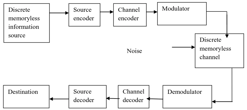
Figure 1: Model of Digital Communication System
1.1 Application of Algebraic Coding:
Source Coding:
Efficient communication from a source to a user destination is attained through source coding.The process by
which this representation is accomplished is called source encoding. The device that performs the
representation is called a source encoder. For the source encoder to be efficient, we require knowledge
of the statistics of the source. In particular, if some source symbols are known to be more probable
than others, then we may exploit this feature in the generation of a source code by assigning short
code words co frequent source symbols, and long code words to take source symbols. We refer to
such a source code as a variable-length code.
The Morse code is an example of a variable- length code. In the Morse code, the letters of the
alphabet and numerals are encoded into streams of marks and spaces, denoted as dots "." and dashes
"-", respectively. In the English language, the letter E occurs more frequently than the letter Q, for
example, so the Morse code encodes E into a single dot".", the shortest code word in the code, and it
encodes Q into"---. -", the longest code word in the code.
Our primary interest is in the development of an efficient source encoder that satisfies two functional
requirements:
1. The code words produced by the encoder are in binary form.
2. The source code is uniquely decodable, so that the original source sequence can be
reconstructed perfectly from the encoded binary sequence.
Mode
Noise
Discrete
memoryless
information
source
Source
encoder
Channel
encoder
Modulator
Discrete
memoryless
channel
Destination
Source
decoder
Channel
decoder
86 |
P a g e
S k b kBinary
Sequence
Figure 2: Source Encoding
We now consider the scheme shown in Figure 2. It depicts a discrete memory less source whose
output sk is converted by the source encoder into a block of O’s and 1’s, denoted by bk.
We assume that the source has an alphabet with K different symbols, and that the kth symbol, sk
occurs with probability pk, k = 0, 1, ….. , K - 1.
Let the binary code word assigned to symbol sk, by the encoder have length Ik, measured in bits. We
define the average code-word length,
L
of the source encoder as:L
= 1 0K k k k
p l
In physical terms, the parameter
L
represents the average number of bits. per source symbol used in the source encoding process.Let Lmin denote the minimum possible value of
L
.We then define the coding efficiency of the sourceencoder as:
min
L
L
With
L
Lmin, we clearly have
1
. The source encoder is said to be efficient when
approachesunity.
But how is the minimum value Lmin determined?
The answer to this fundamental question is embodied in “Shannon's first theorem: the source-coding
theorem”, which may be stated as follows:
Given a discrete memory less source of entropy H(
), the average code-word lengthL
for any distortion less source encoding scheme is bounded as :L H(
)1.2 Source Coding Theorem
The source coding theorem, Shannon’s first theorem, provides the mathematical tool for
assessing data compaction, that is, lossless compression of data generated by a discrete memoryless
source. The theorem tells us that we can make the average number of binary elements(bits) per source
symbol as small as, but no smaller than the entropy of the source measured in bits.
Discrete
memory less
source
87 |
P a g e
The entropy is a function of the probabilities of the source symbols that constitute the alphabet of the
source. Since entropy is a measure of uncertainty, the entropy is maximum when the associated
probability distribution generates maximum uncertainty.
According to the source-coding theorem, the entropy H(
) represents a fundamental limit on theaverage number of bits per source symbol necessary to represent a discrete memory less source in
that it can be made as small as, but no smaller than, the entropy H(
). Thus withLmin= H(
), we may rewrite the efficiency of a source encoder in terms of the entropy H(
) as :( )
H
L
1.3 Data Compaction
A common characteristic of signals generated by physical sources is that, in their natural form, they contain a
significant amount of information that is redundant, the transmission of which is there fore wasteful of primary
communication resources. For efficient signal transmission, the redundant information should be removed from
the signal prior to trans-mission.
This operation, with no loss of information, is ordinarily-performed on a signal in digital form, in which case we
refer to it as data compaction or loss less data compression.
The code resulting from such an operation provides are presentation of the source output that is not only efficient in
terms of the average number of bits per symbol but also exact in the sense that the original data can be
reconstructed wit h no loss of information.
The entropy of the source establishes the fundamental limit on the removal of redundancy from the data.
Basically, data compaction is achieved by assigning short descriptions to the most frequent
outcomesofthesourceoutputandlongerdescriptionstothelessfrequentones.
II Source Coding Schemes for Data Compaction:
We begin by describing a type of source code known as a prefix code, which is not only decodable but
also offers the possibility of realizing an average code-word length that can be made arbitrarily close
to the source entropy.
Prefix Coding:
Consider a discrete m emory less source of alphabet {s
0, s
1,…., s
K-1}and statistics { p
0, p
1, ……, p
K-1}
·
88 |
P a g e
1
corresponding to any other source sequence. We are specifically interested in a special class
of codes satisfying a restriction known as the prefix condition. To define the prefix
condition, let the code word assigned to source symbol s
kbe denoted by (m
k1, m
k2, ... ,
m
kn), where the individual elements m
k1, m
k2, ... , m
knare O’s and ’s, and n is the
code-word length.
The initial part of the code word is represented by the elements mk1,…mki, for some i
n.Any sequence made up of the initial part of the code word is called a prefix of the code word.
A “prefix code” is defined as a code in which no code word is the prefix of any other code word.
A prefix code has the important property that it is always uniquely decodable. But the converse is not
necessarily true.
Moreover, if a prefix code has been constructed for a discrete memory less source with source
alphabet {so, s1, ... , sK-1} and source statistics {p0, p1... , PK-1} and the code word for symbol sk has
length
lk, k = 0, 1, ... , K - 1, then the code-word lengths of the code always satisfy a certain inequality
known as the Kraft-McMillan Inequality, given by:
1
0
1
2
Kk l
k
Where the factor 2 refers to the radix (number of symbols) in the binary alphabet. It is important to
note, however, that the Kraft-McMillan inequality does not tell us that a source code is a prefix code.
Rather, it is merely a condition on the code-word lengths of the code and not on the code words
themselves.
Huffman Coding:
We next describe an important class of prefix codes known as Huffman codes. The basic idea behind
“Huffman coding" is to assign to each symbol of an alphabet a sequence of bits roughly equal in
length to the amount of information conveyed by the symbol in question. The end result is a source
code whose average code-word length approaches the fundamental limit set by the entropy of a
discrete memory less source, namely, H(
).The essence of the algorithm used to synthesize theHuffman code is to replace the prescribed set of source statistics of a discrete memory less source
with a simpler one. This reduction process is continued in a step-by-step manner until we are left
with a final set of only two source statistics (symbols), for which (0, 1) is an optimal code. Starting
from this trivial code, we then work backward and thereby construct the Huffman code for the given
89 |
P a g e
Specifically, the Huffman encoding algorithm proceeds as follows:
1. The source symbols are listed in order of decreasing probability. The two source symbols of lowest
probability are assigned a 0 and a 1. This part of the step is referred to as a splitting stage.
2. These two source symbols are regarded as being combined into a new source symbol with
probability equal to the sum of the two original probabilities. (The list of source symbols, and
therefore source statistics, is thereby reduced in size by one.) The probability of the new symbol is
placed in the list in accordance with its value.
3.The procedure is repeated until we are left with a final list of source statistics (symbols) of only two
for which a 0 and a 1 are assigned.
The code for each (original) source symbol is found by working backward and tracing the sequence of
Os and 1s assigned to that symbol as well as its successors.
Lempel-Ziv Coding:
Basically, encoding in the Lempel-Ziv algorithm is accomplished by parsing the source data stream
into segments that are the shortest Sub sequences not encountered previously. To illustrate this simple
yet elegant idea, consider the example of an input binary sequence specified as follows:
000101110010100101…
It is assumed that the binary symbols 0 and 1 are already stored in that order in the code book.
We thus write:
Subsequences stored: 0, 1
Data to be parsed: 000101110010100101…
The encoding process begins at the left. With symbols 0 and 1 are already stored, the shortest
subsequence of the data stream encountered for the first time and not seen before is 00;
So we write:
Subsequences stored: 0, 1, 00
Data to be parsed: 0101110010100101...
90 |
P a g e
Subsequences stored: 0, 1, 00, 01
Data to be parsed: 01110010100101...
The next shortest subsequence not encountered previously is 011; hence, we write:
Subsequences stored: 0, 1, 00, 01, 011
Data to be parsed: 10010100101…
We continue in the manner described here until the given data stream has been completely passed.
Thus, for the example at hand, we get the code book of binary subsequences shown in the second row
of Figure 3 below, illustrating the encoding process performed by the Lempel Ziv - algorithm on the
binary
Sequence 000101110010100101....
Figure 3:
Numerical positions: 1 2 3 4 5 6 7 8 9
Subsequences: 0 1 00 01 011 10 010 100 101
Numerical representation: 11 12 42 21 41 61 62
Binary encoded blocks: 0010 0011 1001 0100 1000 1100 1101
The first row shown in this figure merely indicates the numerical positions of the individual
subsequences in the code book. We now recognize that the first subsequence of the data stream, 00, is
made up of the concatenation of the first code book entry, 0, with itself; it is therefore represented by
the number 11.
The second subsequence of the data stream, 01, consists of the first code book entry, 0, concatenated
with the second code book entry, 1; it is therefore represented by the number 12. The remaining
subsequences are treated in a similar fashion. The complete set of numerical representations for the
various subsequences in the code book is shown in the third row of Figure 3.
As a further example illustrating the composition of this row, we note that the subsequence 010
consists of the concatenation of the subsequence 01 in position 4 and symbol 0 in position 1; hence,
the numerical representation41. The last row shown in Figure 3 is the binary encoded representation
of the different subsequences of the data stream.
The last symbol of each subsequence in the code book (i.e., the second row of Figure 3) is an
Innovation symbol, which is so called in recognition of the fact that its appendage to a particular
91 |
P a g e
Correspondingly, the last bit of each uniform block of bits in the binary encoded representation of the
data stream (i.e., the fourth row in Figure 3) represents the innovation symbol for the particular
subsequence under consideration. The remaining bits provide the equivalent binary representation of
the "pointer” to the root subsequence that matches the one in question except for the innovation
symbol.
The decoder is just as simple as the encoder. Specifically, it uses the pointer to identify the root
subsequence and then appends the innovation symbol. Consider, for example, the binary encoded
block 1101 in position 9. The last bit, 1, is the innovation symbol. The remaining bits, 110, point to
the root subsequence 10 in position 6. Hence, the block 1101 is decoded into 101, which is correct.
III CONCLUSION
We therefore conclude that by making the order of an extended prefix source encoder large enough,
we can make the code faithfully represent the discrete memoryless source
as closely as desired.In another words, the average code-word length of an extended prefix code can be made as small as the entropy
of the source provided the extended code has a high enough order, in accordance with the source-coding
theorem.
Thus, we have demonstrated that the source coding theorem (shannon’s first theorem) provides the
algebraic coding tools of using source coding schemes for assessing data compaction, that is, lossless
compression of data generated by a discrete memory less source to attain efficiency in digital
communication systems of Digital India Programme which is critical for it’s success.
REFERENCES
[1] Digital India ebook published by the Government of India, 12 December 2015.
[2] J.Adamek, Foundations of Coding (New York: Wiley, 1991).
[3] N. Abramson, Information Theory and Coding ( New York: McGraw-Hill, 1963).
[4] J.P.Costas, “Poisson, Shannon and the radio amateur,” Proceedings of the IRE, vol.47,
pp. 10 - 21, 1949.
[5] C.E.Shannon,” Communications in the presence of noise,” Proceedings of the IRE, vol.37,
pp. 2058-2068, 1956.
[6] J.B.Anderson and S.Mohan, Source and Channel Coding: An Algorithm Approach( Boston,
Mass: Kluwer Academic,1991).
[7] J.B. Anderson, Digital Transmission Engineering (Piscataway, N.J.: IEEE Press,1999).
[8] R.B.Ash, Information Theory (New York: Wiley, 1965).
[9] E.R. Berlekamp, Algebraic Coding Theory (New York: McGraw-Hill, 1968).
[10] R.E.Blahut, Digital Transmissions of Information (Reading, Mass.: Addison- Wesley,1990).
[11] Y.Akaiwa, Introduction to Digital Mobile Communication.
[12] G.D.Forney, M.V.Eyuboglu, “Combined equalization and coding using precoding,” IEEE
92 |
P a g e
[13] J.P.Costas, “Poisson, Shannon and the radio amateur,” Proceedings of the IRE, Vol.47,
pp.2058-2068, 1959.
[14] R.C. Bose, D.K.Ray-Chaudhuri, “On a class of error correcting binary group codes,”
Information and Control, Vol.3, no.1, pp. 68 -79 , 1960.
[16] V.K. Bharagava, “Forward error correction schemes for digital communications,” IEEE Communications