Computational storage: an efficient
and scalable platform for big data and HPC
applications
Mahdi Torabzadehkashi
1,2*, Siavash Rezaei
1,2, Ali HeydariGorji
1,2, Hosein Bobarshad
2, Vladimir Alves
2and Nader Bagherzadeh
1Abstract
In the era of big data applications, the demand for more sophisticated data centers and high-performance data processing mechanisms is increasing drastically. Data are origi-nally stored in storage systems. To process data, application servers need to fetch them from storage devices, which imposes the cost of moving data to the system. This cost has a direct relation with the distance of processing engines from the data. This is the key motivation for the emergence of distributed processing platforms such as Hadoop, which move process closer to data. Computational storage devices (CSDs) push the “move process to data” paradigm to its ultimate boundaries by deploying embedded processing engines inside storage devices to process data. In this paper, we intro-duce Catalina, an efficient and flexible computational storage platform, that provides a seamless environment to process data in-place. Catalina is the first CSD equipped with a dedicated application processor running a full-fledged operating system that provides filesystem-level data access for the applications. Thus, a vast spectrum of applications can be ported for running on Catalina CSDs. Due to these unique features, to the best of our knowledge, Catalina CSD is the only in-storage processing platform that can be seamlessly deployed in clusters to run distributed applications such as Hadoop MapReduce and HPC applications in-place without any modifications on the underlying distributed processing framework. For the proof of concept, we build a fully functional Catalina prototype and a CSD-equipped platform using 16 Catalina CSDs to run Intel HiBench Hadoop and HPC benchmarks to investigate the benefits of deploying Catalina CSDs in the distributed processing environments. The experimental results show up to 2.2× improvement in performance and 4.3× reduction in energy consumption, respectively, for running Hadoop MapReduce benchmarks. Addition-ally, thanks to the Neon SIMD engines, the performance and energy efficiency of DFT algorithms are improved up to 5.4× and 8.9×, respectively.
Keywords: Computational storage, In-storage processing, Near-data processing, SSD, Big data, Hadoop, HPC, DFT, System-on-chip
Open Access
© The Author(s) 2019. This article is distributed under the terms of the Creative Commons Attribution 4.0 International License (http://creat iveco mmons .org/licen ses/by/4.0/), which permits unrestricted use, distribution, and reproduction in any medium, provided you give appropriate credit to the original author(s) and the source, provide a link to the Creative Commons license, and indicate if changes were made.
RESEARCH
*Correspondence: [email protected]
1 University of California,
Introduction
The modern human’s life has been technologized, and nowadays, people rely on big data applications to receive services such as healthcare, entertainment, government services, and transportation in their day-to-day lives. As the usage of these services becomes uni-versal, people generate more unprocessed data, which increases the demand for more sophisticated data centers and big data applications. At current pace, 2.5 quintillion
bytes of data is created each day [1]. Due to the huge volume of data created every
sec-ond, new concepts such as the age of information (AoI) has been established to access
the latest version of data [2]. According to the well-known 4V’s characteristics of big
data, the big data applications need to deal with a very large Volumes of data, which are
in Various types, and their Velocity is more than conventional data, while the data Verac-ity is not confirmed [3].
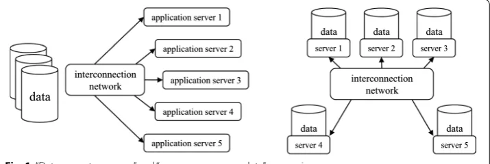
To process data with the aforementioned characteristics, data should frequently move between storage systems and memory units of the application servers. This high-cost data movement imposes energy consumption and degrades the performance of big data applications. To overcome this issue, data processing has moved toward a new
para-digm: “move process to data” rather than moving high volumes of data. Figure 1
com-pares the traditional “data move to process” concept versus the “move process near data”
paradigm.
In the modern clusters, nodes are connected through a low-latency and power-hungry
interconnect network such as InfiniBand [4] or Myrinet [5]. In such systems, moving
data can be more expensive than processing data [6], and moving the data through an
interconnect network is much more costly. In fact, accessing and transferring stored data from storage systems is a huge barrier toward reaching compelling performance
and energy efficiency. To deal with this issue, some frameworks such as Hadoop [7]
pro-vide mechanisms to process data near where they reside. In other words, these frame-works push process closer to data to avoid massive data movements between storage systems and application servers.
In-storage processing (ISP) is the concept of pushing the process closer to data in its ultimate boundaries. This technology proposes utilizing embedded processing engines inside the storage devices to make them capable of running user applications in-place, so data do not need to leave the device to be processed. This technology has been around for a few years. However, the modern solid-state drives (SSDs) architecture, as well as
data
application server 1
application server 2
application server 3
application server 4
application server 5
interconnection network
data
server 1
data
server 2
data
server 3
data
server 4
data
server 5
interconnection network
the availability of powerful embedded processors, make it more appealing to run user applications in-place. SSDs deliver higher data throughput in comparison to hard disk drives (HDDs). Additionally, in contrast to the HDDs, the SSDs can handle multiple I/O commands at the same time. These differences have motivated researchers to modify applications based on the modern SSD architectures to improve the performance of the
applications significantly [8].
The SSDs contain a considerable amount of processing horsepower for managing flash memory array and providing a high-speed interface to host machines. These processing capabilities can provide an environment to run user applications in-place. Based on the reasons mentioned above, this paper focuses on the modern SSD architecture, and in the rest of the paper, computational storage device (CSD) refers to an SSD capable of run-ning user applications in-place.
In an efficient CSD architecture, the embedded ISP engine has access to the data stored in flash memory array through a low-power and high-speed link. Thus, the deployment of such CSDs in clusters can increase the overall performance and efficiency of big data and high-performance computing (HPC) applications. The CSDs and the Hadoop
plat-form both emerged based on the concept of “move process closer to data,” and they both
can be deployed simultaneously in a cluster. This combination can minimize the data movement and increase efficiency for running big data applications in a Hadoop cluster. However, HPC clusters that are not developed based on the Hadoop platform can still utilize CSDs to improve performance and energy consumption.
Processing user applications inside storage units without sending data to the host pro-cessor seems appealing; however, proposing a flexible and efficient CSD architecture has the following challenges.
1. ISP engine: SSDs come with multiple processing cores to run the conventional SSD controller routines. These cores can be utilized for running user applications as well. However, there are two major problems in utilizing the existing SSD cores for in-storage processing. First, these cores are usually busy doing normal SSD operations and using them for running user applications can negatively affect the I/O perfor-mance of the drive. Second, these processing engines are usually real-time cores such as ARM Cortex-R series, which limits the category of the applications that can efficiently run on these cores; also, user applications need major modifications to be able to run on these cores.
2. Host-CSD communication: In a CSD architecture, there should be a mechanism for the communication between host and CSD to submit ISP commands from the host to CSD and receive the results. The conventional SSDs have one physical link con-nected to the host, which is designed for transferring data. There are many protocols
for sending data through this link such as SATA [9], SAS [10], and NVMe over PCIe
[11]. None of these protocols are designed for sending ISP commands and results.
Thus, this is the responsibility of the CSD designer to provide an ISP communication protocol between host and CSD.
data, and any application running in-place should not expect to be able to access the filesystem-level data. This limits the type of programming models available for devel-oping ISP-enabled applications, and also the reuse of other applications. Hence, the CSD designer should provide a mechanism to access the filesystem metadata inside the ISP engine so that applications that are running in-place can open files, process data, and finally create output files to write back the results.
4. Host-CSD data synchronization: In a CSD-equipped host, both host and ISP engine have access to the same flash memory array. In such a system, without a synchroni-zation mechanism, these two machines may not be able to see each other’s modifica-tions and could result in data corruption.
5. CSD as an augmentable resource: Adding CSDs to a host machine should not limit the host from accessing the data and processing it. The processing horsepower of the CSDs should be an augmentable resource so that the host and CSDs could process data simultaneously. If processing an application in CSD interferes with the host’s access to the data, this would dramatically decrease the utilization of the host and the efficiency of the whole system. A well-designed CSD architecture allows the host to access data stored in the flash memory at any time.
6. Adaptability: CSDs should provide a flexible environment for running different types of applications in-place. If the ISP engine of a CSD supports very limited program-ming languages or needs users to rewrite the application based on a specific pro-gramming model, this can affect the adoptability of the CSD significantly.
7. Distributed in-storage processing: A single CSD with limited processing horsepower may not be able to enhance an application’s performance significantly, so in many cases, there should be multiple CSDs orchestrating together to deliver compelling performance improvement. For doing such distributed processing, CSD designers need to provide the required tools for implementing a distributed processing envi-ronment among multiple CSDs.
8. ISP for high-performance computing: Highly demanding applications such as HPC algorithms can potentially run inside CSDs. However, to serve this class of applica-tions properly, CSDs should be able to boost their performance for some specific applications. In other words, the CSD architecture should be customizable to run some applications in an accelerated mode. Hence, CSD designers are required to provide ASIC- or FPGA-based accelerators to run highly demanding applications satisfactorily.
In this paper, we propose an efficient CSD platform, named Catalina, which addresses all the challenges mentioned above and is flexible enough to run HPC applications in-place
or playing the role of an efficient DataNode in a Hadoop cluster. Catalina is equipped
with a full-fledged Linux operating system (OS) running on a quad-core ARM 64-bit application processor which is dedicated to run user applications in-place. Catalina
uti-lizes a Xilinx Zynq Ultrascale+ MPSoC [12] as the main processing engine and contains
CSDs [13]. This property makes it easier to adopt this technology in Hadoop clusters. For the proof of concept, we developed a fully functional Catalina CSD prototype and built a platform equipped with 16 Catalina CSDs.
The contributions of this paper can be summarized as follows:
• Proposing the deployment of computational storage devices in clusters, and end-to-end integration of CSDs in clusters for running Hadoop MapReduce and HPC appli-cations.
• Describing the hardware and software architecture of Catalina as the first computa-tional storage device which is seamlessly adoptable in Hadoop and MPI-based clus-ters without any modification in the cluster’s software or hardware architecture. • Prototyping Catalina CSD and developing a platform equipped with 16 Catalina
CSDs to practically evaluate the benefits of deployment of computational storage devices in the clusters.
• Exploring the performance and energy consumption of CSD-equipped clusters using Intel HiBench Hadoop benchmark suite as well as 1D-, 2D-, and 3D-DFT operations on large datasets as the HPC benchmarks.
The rest of this paper is organized as follows: “Background” section reviews subjects
covered in this paper, such as the modern SSD architecture, ISP technology, and Hadoop
platform architecture. In “Method” section, we present the hardware and software
archi-tecture of Catalina CSD and describe the unique features that make it capable of seam-lessly running a wide spectrum of applications in-place. This section also illustrates the developed Catalina prototype and how it can be deployed in clusters to run Hadoop
MapReduce and HPC applications. “Results and discussion” section investigates the
benefits of deploying the proposed solution for running Hadoop MapReduce and HPC applications on clusters. This section demonstrates how increasing the number of
Cat-alina CSDs improves energy consumption and performance of the applications. “Related
works” section reviews the related works in the field of in-storage processing, and “ Con-clusion” section concludes the paper with some final remarks.
Background
The storage system, where data originally reside, plays a crucial role in the performance of applications. In a cluster, the data should be read from the storage system to mem-ory units of the application servers to be processed. As the size of data increases, the role of the storage system becomes more important since the nodes need to talk to the storage units more frequently to fetch data and write back the results. Recently, cluster architects have considered solid-state drives (SSDs) over hard disk drives (HDDs) as the major storage units in modern clusters due to better power efficiency and higher data transition rate [14].
to communicate with the host, such as NVMe over PCIe [11]. Implementing such inter-faces require embedding more processing horsepower inside SSDs. A modern SSD con-troller is composed of two main parts: 1—front-end (FE) processing engine providing high-speed host interface protocol such as NVMe/PCIe, and 2—back-end (BE) process-ing engine which deals with flash management routines. These two engines talk to each other to accomplish host’s I/O commands.
A NAND flash memory chip is a package containing multiple dies. A die is the small-est unit of flash memory that can independently execute I/O commands and report status. Each die is composed of a few planes, and each plane contains multiple blocks. Erasing is performed at the block-level, so a flash block is the smallest unit that can be erased. Inside each block, there are several pages which are the smallest units that can be programmed and written. The key point in this hierarchical architecture is the pro-grammable unit versus the erase unit. The NAND flash memory can be programmed in page-level, which is usually 4 to 16 kB, while the erase operation cannot be done on a smaller segment than a block which is few megabytes of memory. Also, each flash block can be erased for a finite number of times, and flash blocks wear as erase operations take place, so it is important to balance the number of erase operations among all the flash blocks of an SSD. The process of leveling the number of erase operations is called wear leveling. In addition, the logical address exposed to the host is different from physical block addresses, so there are multiple tables for logical and physical address translation. The flash translation layer (FTL) is composed of all the routines needed to manage flash memory arrays such as logical block mapping, wear leveling, and garbage collection. Overall, the BE processing subsystem of a modern SSD architecture handles FTL, while the FE subsystem provides protocols to communicate with the host. The details of FTL processes and NVMe protocol are out of the scope of this paper. The high-level
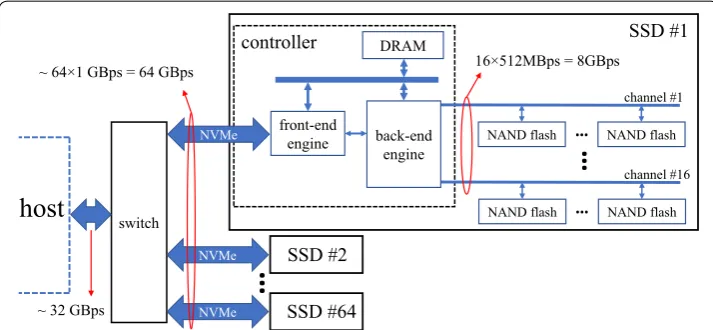
architec-ture of a modern SSD is demonstrated in Fig. 2.
The Webscale data center designers have been trying to develop storage architectures that favor high-capacity hosts, and this fact is highlighted at OpenCompute (OCP) by
Microsoft Azure and Facebook that call for up to 64 SSDs attached to each host [15].
front-end
engine NAND flash … NAND flash
channel #1
NAND flash … NAND flash channel #16
…
host
16×512MBps = 8GBps
back-end engine DRAM
controller
switch
NVMe NVMe
NVMe
…
SSD #1
~ 32 GBps
SSD #2
SSD #64
~ 64×1 GBps = 64 GBps
In Fig. 2, such a storage system is shown where 64 SSDs are attached to a host. For the sake of simplicity, only the details of one SSD are demonstrated. Modern SSDs usu-ally contain 16 or more flash memory channels which can be utilized concurrently for flash array I/O operations. Considering 512 MBps bandwidth per channel, the internal bandwidth of an SSD with 16 flash memory channels is 8 GBps. This huge bandwidth decreases to about 1 GBps due to the complexity of the host interface software and hard-ware architecture. In other words, the accumulated bandwidth of all internal channels of the 64 SSDs reaches the multiplication of the number of SSDs, number of channels per SSD, and 512 MBps (bandwidth of each channel) which is equal to 512 GBps. While the accumulated bandwidth of the SSDs’ external interfaces is equal to 64 multiply by 1 GBps (the host interface bandwidth of each SSD) which is 64 GBps. However, In order to talk to the host, all SSDs required to be connected to a PCIe switch. Hence, the avail-able bandwidth of the host is limited to 32 GBps.
Overall, there is a 16× gap between the accumulated internal bandwidth of all SSDs
and the bandwidth available to the host. In other words, for reading 32 TB of data, the host needs 16 min while internal components of the SSDs can read the same amount of data in about 1 min. Additionally, in such storage systems, data need to continuously move through the complex hardware and software stack between hosts and storage units, which imposes a considerable amount of energy consumption and dramatically decreases the energy efficiency of large data centers. Hence, storage architects need to develop techniques to decrease data movement, and ISP technology has been intro-duced to overcome the aforementioned challenges by moving process to data.
In a traditional CPU-centric scheme, data always move from storage devices to CPU
to be processed, and this mechanism, which is inherently limited by the von Neumann
bottleneck, is the root cause of the challenges above, especially when many SSDs are
con-nected to a host. ISP technology proposes a contrary approach to push the “move process
to data” to its ultimate boundaries where a processing engine inside storage unit takes advantage of high-bandwidth and low-power internal data links and processes data
in-place. In fact, “move process to data” is the concept that leads to the emergence of both
ISP and distributed processing platforms such as Hadoop. Later in this section, it will be described how the Hadoop platform and ISP technology can simultaneously work together in a cluster.
The ISP technology minimizes the data movements in a cluster and also increases the processing horsepower of the cluster by augmenting power-efficient processing engines to the whole system. This technology can potentially be applied to both HDDs and SSDs; however, modern SSD architecture provides better tools for developing such technolo-gies. The SSDs which can run user application in-place are called computational storage devices (CSDs). These storage units are augmentable processing resources, which means they are not designed to replace the high-end processors of modern servers. Instead, they can collaborate with the host’s CPU and augment their efficient processing horse-power to the system.
It is noteworthy that CSDs are fundamentally different than object-based storage
sys-tems such as Seagate Kinetic HDDs [16], which transfer data at the object-level instead
ID. Consequently, the host does not require to maintain metadata of block addresses of the object. On the other hand, CSDs can run user applications in-place without sending data to a host. There is a vast literature in this field that proposed different CSD architec-tures and investigated the benefits and challenges of deploying CSDs for running
appli-cations in-place. In “Related works” section, we will review the important works in this
field.
A while ago, when the cost of data movement was insignificant in comparison with the computational cost, there could be a centralized storage system, and other hosts could send requests to it to fetch data blocks. With this mechanism and today’s volume of data, a data-intensive application requires large amounts of data to be fetched from the stor-age system, and such huge data movements drastically increase energy consumption. With the emergence of big data, the storage system can no longer be centralized, and the traditional approaches come short of satisfying super-scale applications’ demands, which call for scalable processing platforms. To answer these demands, distributed pro-cessing platforms such as Hadoop are proposed to process data near where they reside [17].
Hadoop has emerged as the leading computing platform for big data analytics and
is the backbone of hyperscale data centers [18], where hundreds to thousands of
com-modity servers are connected to provide service to clients. The Hadoop distributed processing platform consists of two main parts, namely Hadoop filesystem (HDFS) and MapReduce engine. HDFS is the underlying filesystem of the Hadoop platform, and it is responsible for partitioning the data to blocks and distribute the data blocks among nodes. HDFS also generates a certain number of replicas of each block to make the
sys-tem resilient against storage or node failures. It consists of a NameNode host which takes
care of filesystem metadata such as the location of the data block and status of the other
nodes, and multiple DataNodes hosts that store the data blocks.
On top of HDFS, MapReduce platform takes advantage of the partitioned data and runs map and reduce functions and orchestrates the cluster nodes to run distributed applications while data movements are minimalized. The Apache MapReduce 2 (YARN)
is one of the well-known MapReduce platforms [19]. YARN agents manage the
proce-dure of running map tasks, performing shuffle and sort, and running the reduce func-tions to generate the output of the MapReduce application. The most important agents
in the YARN framework are global resource manager (RM), one node manager (NM) per
processing node, and an application master (AM) per MapReduce application.
The RM has a list of all the resources available in the cluster and manages the
high-level resource allocations to MapReduce applications. On the other hand, NMs that run
on the processing nodes manage the local hosts’ resources. The RM regularly talks to the
NMs to manage all the resources and poll the status of the nodes. For each MapReduce
application, there is an AM to observe and manage the progress of the application.
Regu-larly, RM runs in the same node that HDFS NameNode runs (head node), and NMs run
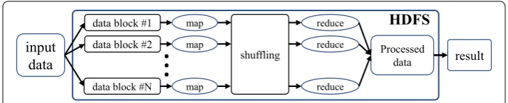
together with the HDFS DataNodes. Figure 3 shows a high-level overview of a
MapRe-duce application on a Hadoop platform.
In the Hadoop environment, data should initially be imported to the HDFS. This process includes partitioning the input data to data blocks and storing them in the
fashion. Since map functions preferably process the local data blocks, the MapReduce framework is known for moving process closer to data in order to improve the power efficiency and performance of the applications.
A MapReduce application targets a set of input data blocks as well as the user-defined map and reduce functions. The procedure starts by running the map function on the
tar-geted data blocks. Map function instances run concurrently on the DataNodes, consume
data blocks, and produce a set of key/value pairs to be used as the input of the reduce
function. These intermediate key/value pairs are stored locally on the DataNodes that
execute the map function and should be shuffled, sorted, and transferred to the nodes which run the reduce tasks. The Hadoop framework stores the output of the reduce function in HDFS, and subsequently, it can be imported to a host’s local filesystem.
The Hadoop MapReduce platform provides an efficient environment for processing large datasets in a distributed fashion. However, there are research papers in the liter-ature that optimize Hadoop MapReduce platform for different workloads. Generally, HDFS partitions data to fixed-size 64 or 128 megabytes data blocks. The data-inten-sive MapReduce applications send numerous I/O requests to the Hadoop I/O sched-uler, and this leads to a long queue of I/O requests in the schedsched-uler, and consequently, a substantial increase in the data latency. Bulk I/O dispatch (BID) is proposed as a Hadoop I/O scheduler that is optimized for data-intensive MapReduce applications
and can improve the access time of such applications significantly [20].
In some big data applications, the data that are generated in a processing node will be consumed by the same node in the near future. The lineage-aware data management (LDM) is proposed for Hadoop-based platforms to exploit this data locality to decrease
the network footprint [21]. LDM develops a data block graph which is used to
character-ize the future data usage pattern. Using this information, it defines tier-aware storage policies for the Hadoop nodes to mitigate the impact of data dependency.
The Hadoop strategy of “processing data close to where they reside” is completely
aligned with the ISP paradigm [22]. So, they can fortify each other’s benefits when
both are deployed concurrently in a cluster. In other words, Hadoop-enabled CSDs
can play both roles of fast storage units for conventional Hadoop DataNodes and
ISP-enabled DataNodes simultaneously, resulting in augmentation of processing
horse-power of the CSDs to the Hadoop cluster.
Although CSDs can improve the overall performance of a MapReduce applica-tion by augmenting their processing engine to the Hadoop framework, this is not the primary advantage of deploying CSDs in the clusters. Potentially, increasing the total horsepower of a cluster can be achieved by adding more commodity nodes to a
input data
data block #1
Processed data data block #2
data block #N
...
result
HDFS
map map
map
reduce reduce
reduce
shuffling
cluster. What makes CSDs distinguishable is, in fact, utilizing the high-performance and power-efficient internal data links of the modern SSD architecture for running Hadoop MapReduce applications.
On the other hand, well-designed CSDs can be deployed to run HPC applications in-place. However, CSDs need to deliver a compelling performance when running HPC applications; otherwise, it is hard to justify the complexity of deploying CSDs in the clus-ters while their performance improvement is not satisfactory. In this paper, we argue that CSDs can considerably improve the performance of HPC applications when they utilize ASIC-based accelerators such as Neon advanced SIMD engines.
Methods: Catalina CSD for MapReduce and HPC applications
We mentioned the challenges for proposing a well-designed CSD architecture in “
Intro-duction” section. Based on these challenges, we set eight design goals to propose an effi-cient and flexible CSD architecture. The design goals are as follows: 1—A desired CSD architecture should avoid using real-time processors that are originally intended to run conventional flash management routines for running user applications in-place. Instead, it should contain an ISP-dedicated application processor. 2—There should be a TCP/IP link between the host and the ISP engine, allowing the applications running on the host and CSD to communicate with each other. 3—The ISP engine should have access to the filesystem metadata. 4—Since both host and ISP engine have access to the flash mem-ory concurrently, there should be a synchronization mechanism. 5—Both host and ISP engine should be able to interact with the flash storage simultaneously. 6—There should be an OS running inside the CSD. This OS provides a flexible environment to run a vast spectrum of applications in-place. 7—The desired CSD should support the distributed processing platforms such as Hadoop and message passing interface (MPI). 8—The CSD should have potentials to implement ASIC- and FPGA-based accelerator engines to run CPU-intensive applications in-place with a compelling performance.
In this section, we describe the hardware and software architecture of Catalina, which is designed to satisfy all the design goals mentioned above. This section is composed of four subsections. In the first subsection, different hardware components of Catalina are described, and we discuss how they work together. The second subsection defines Catalina software layers that make it possible to send ISP commands, processing data in-place, and writing the results back. The third subsection demonstrates the fully func-tional Catalina prototype used to investigate the benefits of deploying CSDs in the clus-ters. The last subsection demonstrates how multiple Catalina CSDs can be deployed to run Hadoop MapReduce and HPC applications.
Hardware architecture
Catalina CSD is developed based on Xilinx Zynq Ultrascale+ MPSoC [12]. This device
controller such as the host and flash memory array interfaces. These two subsystems are packaged in one chip with multiple data links connecting them for high-performance and power-efficient intra-chip data transfers. These two subsystems together provide a proper platform for implementing conventional SSD routines as well as running user applications in-place.
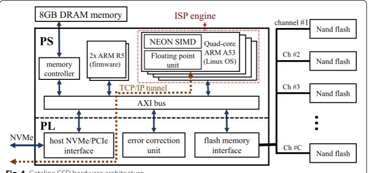
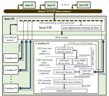
Figure 4 shows the Catalina architecture, implemented using Xilinx Zynq Ultrascale+
MPSoC. On the PL subsystem, there are three conventional components of the control-ler which are host NVMe/PCIe interface, error correction unit, and the flash memory interface. The host interface is responsible for sending and receiving the NVMe/PCIe packets from the host and check the integrity of the payloads. Soft errors can potentially happen in different parts of a device, and SSDs are no exceptions. These errors can hap-pen in the SSD controller and the flash memory packages. There are research works that investigate the effect of the soft errors on the SSD controller and the availability and
reliability of the storage systems [23]. On the other hand, for addressing the soft errors
on the flash memory packages, the error correction unit is utilized to correct the data errors.
The flash memory interface controls the flash memory channels. In Fig. 4, each flash
channel is connected to a set of flash memory packages. Design and implementation of these three components require a considerable amount of engineering resources; how-ever, they are common among all conventional SSDs. We skip the detailed architectures of these components since they are out of the scope of this paper.
On the PS subsystem, there are two ARM Cortex-R5 real-time processors that are used for controlling the components implemented in the PL subsystem as well as run-ning the flash translation layer (FTL) routines. In fact, the conventional firmware rou-tines run on these two real-time processors. One of the real-time processors runs the FE firmware, which controls the host interface module and interprets the host’s I/O com-mands. The other ARM Cortex-R5 processor runs the BE firmware, which is responsible for controlling the error correction and flash interface units. The BE firmware also runs other essential FTL routines such as garbage collection and wear-leveling. The FE and
error correction
unit flash memory interface
…
memory controller
host NVMe/PCIe interface
PL
PS
AXI bus
2x ARM R5 (firmware)
8GB DRAM memory
NVMe
Nand flash
Nand flash
Nand flash
Nand flash
TCP/IP tunnel
channel#1
Ch #2
Ch #3
Ch #C Quad-core
ARM A53 (Linux OS)
NEON SIMD
Floating point unit
ISP engine
BE firmwares work together to receive the host’s I/O commands, interpret them, and execute flash read/write operations.
All of the components mentioned above are common among conventional SSDs; how-ever, Catalina is equipped with a unique ISP subsystem. This subsystem is dedicated to running user applications in-place. It contains a quad-core ARM Cortex-A53 processor which is equipped with Neon SIMD engines and floating-point units (FPUs). The quad-core processor is capable of running a vast spectrum of applications, while Neon SIMD engines can increase the performance of HPC applications. Overall, the quad-core Cor-tex-A53 processor is the main ISP engine of Catalina, and Neon SIMD engines and the FPUs can accelerate user applications that run in-place.
As Fig. 4 demonstrates, both the ISP engine and the two Cortex-R5 real-time
proces-sors which run the conventional flash management routines are connected via an inter-nal Xilinx advanced extensible interface (AXI) bus. The shared AXI bus makes it possible to transfer data between the BE firmware and the ISP engine efficiently. In other words, the ISP engine can bypass the whole NVMe hardware and software stack and access the data stored in the flash memory array directly by communicating to the BE firmware. There is also an 8 GB DRAM memory connected to the AXI bus, which is shared among all the processing units.
Software stack
The Catalina software stack is designed to achieve the goals we set earlier in this sec-tion. The most important part of the software components is an OS running inside the ISP engine. Therefore, we have ported a full-fledged Linux OS running on the quad-core ARM Cortex-A53 processor. Each core of the quad-core processor has a level-one 32 kB instruction cache and a 32 kB data cache. The ARM processor also contains a 1 MB level-two cache, which is used by all the cores. These caches together with the memory unit and the non-volatile flash memory compose a memory hierarchy. The Catalina OS governs the memory hierarchy for data coherency and integrity. Overall, the OS is a flex-ible environment for running user applications in-place as well as implementing other layers of the software stack.
Running an OS inside the CSD comes with complexity and processing overhead. The first challenge to port an OS inside the CSD is to boot the OS together with the conven-tional flash management firmware. At the boot time, the OS and the firmware should boot up concurrently and complete a handshake phase. This procedure adds a consider-able amount of complexity to the design and manufacturing of the CSD. We have suc-cessfully implemented this dual-boot procedure, and the users do not have any concerns regarding this challenge.
On the other hand, the ISP subsystem consumes a portion of the processing budget for running the OS routines. Since the processing budget of the ISP engine is limited, the OS should not consume a big portion of the resources. We have measured the OS rou-tines overhead in different states of the ISP subsystem, and our results showed that the processing overhead of running the OS is at most 2% of the total processing budget of
the Catalina CSD. Figure 5 demonstrates the architecture of the software layers and how
Our first design, named Compstor [24], had a custom-developed software stack, and it was unable to be utilized in the distributed processing environments. This problem is addressed in Catalina design by adopting standard software stacks such as MPI and
Hadoop MapReduce [25]. In Fig. 5 there is a cluster of M hosts connected to a TCP/IP
interconnect, and the host 1 is attached to N Catalina CSDs via a PCIe switch. In this
figure, the lowest layer of the software stack is the BE firmware, which implements the FTL procedures. The BE firmware serves both FE firmware which talks to the host via NVMe protocol and a block device driver implemented in the kernel space of the ISP engine’s OS. The block device driver issues flash I/O commands directly to the BE firmware, so the data link through the block device driver bypasses the NVMe/PCIe software and hardware stack. The block device driver also makes it possible to mount the flash storage inside the Catalina OS. It allows a user application running in-place to have filesystem-level access to the data stored in the flash memory array via a high-performance and low-power internal data link.
On the other hand, the ISP engine should also provide a link between applications that run in-place and applications running on the host, so in addition to the block device driver, we have implemented a TCP/IP tunnel through NVMe protocol to transfer TCP/IP packets between the applications running on the host and the appli-cations running inside Catalina. We have utilized NVMe vendor-specific commands to packetize TCP/IP payloads inside the NVMe packets (TCP/IP tunnels through
user application running in-place
Flash memory array interface CSD block
device driver CSD Linux kernel
space (ARM A53)
Nand flash array CSD controller
PL subsystem CSD Linux user
space (ARM A53)
back-end firmware CSD firmware
(ARM R5)
CSD Linux OS
AXI bus intra-chip
inter-chip
NVMe
front-end firmware
inter-process Catalina #2
Catalina #3
Catalina #N
Catalina #1
AXI bus intra-chip TCP/IP over NVMe tunnel PCIe switch
cluster TCP/IP interconnect
user application running on host
host DRAM memory
host OS
host #1
intra-operating system network
host #3
NVM
e
host #M
Neon SIMD API set
…
…
host #2
NVMe are demonstrated in Fig. 5 by dashed lines). A software layer implemented on both host OS and the Catalina OS provides the tunneling functionality. Since
distrib-uted platforms such as Hadoop MapReduce [17] and MPI [26] are based on TCP/
IP connection, this link plays a crucial role in running distributed applications. As
shown in Fig. 5, all the N Catalina CSDs that are attached to the host 1 can
concur-rently communicate with applications running on the host.
It is worth mentioning that by using Linux TCP/IP packet routing tools, we can cre-ate an internal network in the host OS, and reroute the packets sent or received by the
Catalina CSDs to the other hosts attached to the TCP/IP interconnect (see Fig. 5).
Alter-natively stated, considering several hosts that are connected via a TCP/IP interconnect, and each of them is equipped with multiple Catalina CSDs, the hosts, as well as all the CSDs attached to them, can communicate to each other via a TCP/IP network. Such CSD-equipped cluster architecture benefits from the efficient ISP capabilities of Catalina CSDs to run distributed applications. In fact, the proposed CSD architecture is an aug-mentable processing resource that is adoptable in the cluster without any modifications in the underlying Hadoop or HPC platforms.
Also, the user applications that run in-place have access to Neon SIMD engines via a set of application programming interfaces (APIs) provided by the Catalina OS. Using these APIs, user applications can potentially be accelerated by the Neon SIMD engine. Overall, the user applications have access to three unique tools, including 1—a high-speed and low-power internal link to the data stored in the flash memory, 2—a TCP/ IP link to the applications running on the host, 3—a set of APIs to utilize Neon SIMD engines.
The last layer of the software stack is the synchronization layer between the host and Catalina OSs. These two OSs can access the data stored in the flash memory array at the filesystem-level and concurrently mount the same storage media, which is a problematic behavior without a synchronization mechanism. Since Catalina contains a full-fledged Linux OS and there is a TCP/IP connection to the host, to address the synchronization
issue, we have utilized the Oracle cluster filesystem 2nd version (OCFS2) [27] between
the host and the CSD. Using OCFS2, both the host and Catalina CSD can issue flash I/O commands and mount the shared flash memory natively. This is the main differ-ence between OCFS2 and network filesystem (NFS). In NFS, only one node mounts the shared storage natively, and other nodes use a network connection to access the shared
storage, so NFS limits the data throughput and also suffers from the single point of
fail-ure problem. On the other hand, using OCFS2, all nodes can mount the storage natively.
Catalina prototype
To prove the feasibility of the proposed computational storage solution and also investi-gate the benefits of deploying Catalina CSDs in clusters, we have designed and manufac-tured a fully functional prototype of Catalina which completely aligns with the hardware
and software architecture that has been described in the previous subsections. Figure 6
shows the Catalina CSD prototype. The CSD controller implemented on a Xilinx Zynq
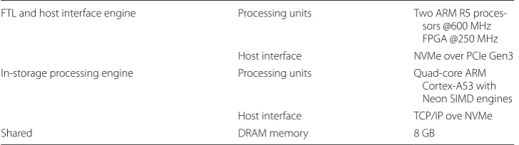
The CSD controller is composed of the PS and PL subsystems that implement the two processing engines of the Catalina CSD, namely the conventional FTL and host interface engine and the ISP engine. The hardware specifications of the Catalina prototype
sepa-rated for these two engines come in Table 1.
The prototype of Catalina is able to execute the host’s I/O commands and also provides a straightforward mechanism for offloading user applications to the CSD via a TCP/IP tunnel through NVMe/PCIe. Considering multiple Catalina CSD prototypes attached to a host, an administrative application on the host can initiate user applications on CSDs while the host and the CSDs’ OSs are being synchronized by the OCFS2 filesystem. The user applications can be developed in any language supported by Linux OS, and they can interact with the flash memory at the filesystem-level, similar to when they run on a conventional host machine.
Despite all of the projected benefits of deploying the CSDs, they should be cost-effec-tive to be adoptable in the clusters. After prototyping Catalina, a sensible cost analysis of manufacturing CSDs can be presented. Compared with a regular SSD based on a con-ventional controller, a CSD should be equipped with more processors to run applica-tions in-place efficiently. Interestingly, according to our observaapplica-tions and also the SSD
bill of material analysis [28, 29], the major difference between an SSD and a CSD
manu-facturing costs would be insignificant, since the SSD manumanu-facturing cost is largely domi-nated by the NAND flash memory. The cost of flash memory chips is about 75% of the
SSD price.1 With other miscellaneous costs (such as DRAM, miscellaneous components,
and manufacturing costs) that would account for 20–25% of the SSD price, the control-ler would account for at most 5% of the SSD price.
flash memory
modules
CSD controller
Fig. 6 Catalina CSD prototype
Table 1 Catalina prototype hardware specifications
FTL and host interface engine Processing units Two ARM R5 proces-sors @600 MHz FPGA @250 MHz Host interface NVMe over PCIe Gen3 In-storage processing engine Processing units Quad-core ARM
Cortex-A53 with Neon SIMD engines Host interface TCP/IP ove NVMe
Shared DRAM memory 8 GB
Deploying Catalina in clusters
Catalina is developed concerning a straightforward deployment in clusters. Since it has all the required features to play the role of a regular processing node, the cluster archi-tects do not have to make major modifications in the underlying platforms for
deploy-ment of the Catalina CSDs. Figures 7, 8 illustrate CSD-equipped Hadoop and MPI-based
clusters, respectively, where a head node is connected to M host machines, and each of
the hosts is equipped with N Catalina CSDs. In such a cluster, all CSDs and conventional
nodes are orchestrating together to improve the performance and efficiency of distrib-uted applications.
NameNode (head node)
DataNode (application host)
DataNode (CSD)
DRAM DN CPU
NN head node
application host #M
Catalina
2
Catalina
N
…
1 a
nil
ata
C
DRAM CPU
application host #1
Catalina
2
Catalina
N
…
Catalina
1
…
DN
DN DN DN DN DN DN
DN NN
DN
CPU
DRAM
Fig. 7 Catalina CSD-equipped Hadoop cluster
MPI coordinator (head node)
MPI worker (application host)
MPI worker (CSD)
DRAM CPU
application host #1
Catalina
2
Catalina
N
…
1
ani
lat
a
C
DRAM CPU
application host #M
Catalina
2
Catalina
N
…
Catalina
1
CPU
DRAM head node
…
In the CSD-equipped Hadoop cluster, the head node runs Hadoop NameNode and
YARN resource manager (RM), while the hosts and Catalina CSDs run DataNodes and
node managers (NMs). In fact, Catalina CSDs play both roles of storage units as well as
efficient DataNodes. Since Hadoop implements its filesystem synchronization
mecha-nism, we exceptionally do not need the OCFS2 filesystem for running Hadoop. However, OCFS2 plays an important role in running MPI-based applications.
Figure 8 illustrates a CSD-equipped cluster based on MPI for running HPC
appli-cations. In this figure, the head node runs an MPI coordinator while the conventional
hosts, and the Catalina CSDs, run the MPI workers. In this MPI-based cluster, each host
is attached to N CSDs, and the data stored on the CSDs are shared between the host
and CSDs, so the MPI workers on the host and the CSDs have access to the shared data. Thanks to the OCFS2 filesystem, the shared data is simultaneously visible to the host and CSDs at the filesystem-level so that the user can freely distribute the processing load among the hosts and the CSD.
Results and discussion
As mentioned in the previous section, deploying Catalina CSDs in clusters is straightfor-ward. After attaching the Catalina CSDs to the host and setting the network configura-tions, the CSDs are exposed to the other hosts in the cluster by their network address (e.g., IP address). From the system-level point of view, the Catalina CSDs are similar to regular processing nodes, and the underlying ISP hardware and software details are invisible to other nodes in the cluster. In this section, we first demonstrate the developed platforms equipped with up to 16 Catalina CSDs and describe how we implemented a CSD-enabled Hadoop and MPI-based clusters on the developed platforms. The second subsection shows the results of running different Hadoop MapReduce and HPC bench-marks and discusses the benefits of deploying Catalina CSDs in clusters.
Experimental setup
The Catalina CSDs are not designed to compete with the modern hosts based on
high-end ×86 processors with tens to hundreds of gigabytes of DRAM. Instead, it is presented
as a resource that augments the processing horsepower of a system and improves the
performance and power efficiency of the applications [25]. However, for getting
consid-erable improvements, we propose attaching multiple Catalina CSDs to host machines.
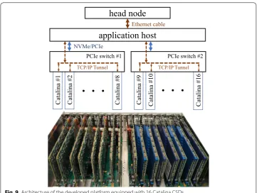
Figure 9 shows the architecture of the developed platform, which contains 16 Catalina
CSD prototypes. We built this platform to investigate the benefits of deploying Catalina CSDs in clusters.
This platform is composed of a conventional host (called the head node) and an
appli-cation host, which is equipped with the Catalina CSDs. These two hosts, along with the Catalina CSDs, form a distributed environment for running Hadoop MapReduce and
MPI-based HPC applications. We use the head node exclusively for running Hadoop
NameNode and the MPI coordinator to eliminate the load of the administrative tasks on
the processing nodes. In other words, the application host and the CSDs are the
process-ing nodes, while the head node is dedicated only for running the administrative tasks.
To extensively investigate the benefits of Catalina CSDs in different environments,
medium, and high. The specifications for the head node and the different application
host’s configurations are summarized in Table 2. In order to attach up to 16 Catalina
CSDs to the application host, we used a Cubix Xpander Rackmount unit [30] which
pro-vides 16 PCIe Gen3 slots. This unit and the attached Catalina CSDs are shown in Fig. 9.
The implementations of the Hadoop and the MPI-based clusters are aligned with the
architectures that are shown in Figs. 7, 8. For implementing the Apache Hadoop
clus-ter, we ran Hadoop NameNode and the Yarn resource manager (RM) on the head node,
while the DataNodes and the node managers (NMs) run on the application host, and the
Catalina CSDs that are attached to the application host. The communication between
the head node and the application host is through an Ethernet cable, while Catalina CSDs communicate via the developed TCP/IP through NVMe link.
On the other hand, for running the HPC application based on MPI, we use the head
node for running the MPI coordinator application which initiates and organizes the MPI
workers that run on the application host and the Catalina CSDs. In this case, the OCFS2
1#
ani
lat
a
C
. . .
application host
NVMe/PCIe
Catalina #2 Catalina #8 PCIe switch #1
TCP/IP Tunnel
Catalina #9 Catalina #1
0
Catalina #1
6
. . .
PCIe switch #2TCP/IP Tunnel
head node
Ethernet cableFig. 9 Architecture of the developed platform equipped with 16 Catalina CSDs
Table 2 Specifications of the hosts in the developed system for running experiments Feature Head node Application host configurations
Low Medium High
Processor Xeon E5-2620 v4 Core i3-8100T Core i7-7700 Xeon E5-2620 v4 Memory 32 GB (DDR 4) 32 GB (DDR 4) 32 GB (DDR 4) 32 GB (DDR 4) Storage 4× Samsung 850
filesystem synchronizes the filesystems of the Catalina CSDs and the application host, so
at any given time the application host can access the whole data stored on all the CSDs
directly, while each CSD only has access to its local data.
As previously discussed, all the packets from/to the CSDs are routed inside the
appli-cation host. This mechanism provides a flexible networking environment without using an extra network switch. However, there is a cost for having such a flexible network. The
application host needs to consume a portion of its processing horsepower to route the
packets. In our design, for each CSD added to application host, an insignificant amount
of the host’s CPU is consumed for the routing mechanism. We have measured this
net-working overhead for different workloads. In highly congested scenarios, the application
host consumed at most 3.5% of its processing horsepower for the routing the TCP/IP
packets among CSDs. This overhead is considered in the results in this section.
Benchmarks and results
This subsection is composed of two parts. First, we describe the targeted Hadoop MapReduce benchmarks and report the performance and energy consumption of ning the benchmarks for different configurations to investigate the benefits of run-ning Hadoop MapReduce applications in-place. Then, we show the results for runrun-ning 1D, 2D, and 3D discrete Fourier transform (DFT) algorithms utilizing the Neon SIMD engines of Catalina CSDs. For reporting the performance, we measure the total elapsed time of running a benchmark on the developed platform for a given configuration. On the other hand, to measure the energy consumption, we use a power meter to measure the power consumption of the platform. Using the logging tool provided by the power meter, we calculate the total energy consumption for running a benchmark. However, we deducted the idle energy consumption from the total calculated energy consumption for all the experiments to eliminate the energy consumption imposed by miscellaneous devices such as the cooling system.
Hadoop MapReduce benchmarks and results
For running Apache Hadoop MapReduce applications on the developed platform, we have
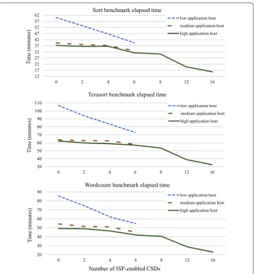
used a subset of the Intel HiBench benchmark suite [31] which includes Sort, Terasort, and
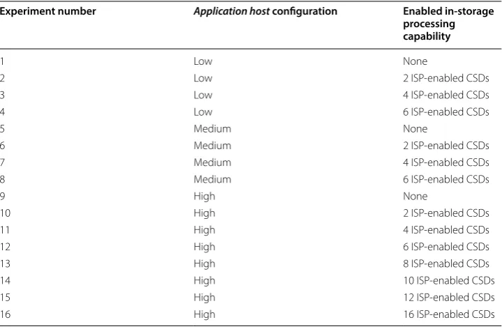
Wordcount benchmarks. We believe that extensive experiments on these three benchmarks can show the potentials of CSD architectures running Hadoop MapReduce applications. These benchmarks have been executed on 16 different platform configurations, which are
listed in Table 3. In all the experiments, the head node specification is fixed and matches
with Table 2, and the number of mappers and reducers tasks are 2000 and 200, respectively.
The application host uses all the attached Catalina CSDs as the storage units (6 CSDs
in the low and medium configurations; and 16 CSDs in the high configuration), while in
each configuration, a certain number of the ISP engines of the CSDs are enabled to run MapReduce application in-place. This way, the scalability of deploying Catalina CSDs in clusters can be investigated. The data size for Sort, Terasort, and Wordcount bench-marks are 8 GB, 1.3 GB, and 80 GB, respectively.
the 16 different platform configurations, and each experiment has been repeated 30 times that gives us a total of 1440 MapReduce tests.
As previously stated, in all experiments, the application host uses all connected
Cat-alina CSDs as storage units, however, in each test, a certain number of CSDs are enabled to run MapReduce application in-place and play the role of a processing node.
Fig-ures 10, 11 shows the Hadoop MapReduce experiments performance and energy
con-sumption results, respectively.
The diagrams in Fig. 10 show that increasing the number of ISP-enabled CSDs
decreases the elapsed time for all benchmarks. The performance of the high-configured
application host platform increased up to 2.2× when the ISP engines of all 16 Catalina CSDs are enabled. Thus, deploying ISP-enabled CSDs increases the performance of the Hadoop MapReduce benchmarks significantly.
Also, according to these diagrams, the elapsed time for running the MapReduce
benchmarks on the low-configured application host platform equipped with six Catalina
CSDs is close to the elapsed time of running the benchmarks on the high-configured
application host platform with no enabled ISP engine. So, only six Catalina CSDs can improve the performance of a low-end host close to the performance of a high-end host. As we previously discussed, the cost of implementing the ISP engine inside the SSDs is negligible compared to the total cost of manufacturing an SSD, so ISP technology
can considerably improve the performance of Hadoop clusters economically. Figure 11
shows the energy consumption results of running the Hadoop MapReduce benchmarks on the developed platform for different configurations.
According to Fig. 11, the energy consumption of running the benchmarks on the low
-configured application host platform decreases up to 36% by deploying six ISP-enabled
Catalina CSDs. This improvement for the high-configured application host platform
equipped with 16 ISP-enabled Catalina CSDs reaches to 4.3×.
Table 3 Different configurations for running Hadoop MapReduce benchmarks
Experiment number Application host configuration Enabled in-storage processing capability
1 Low None
2 Low 2 ISP-enabled CSDs
3 Low 4 ISP-enabled CSDs
4 Low 6 ISP-enabled CSDs
5 Medium None
6 Medium 2 ISP-enabled CSDs
7 Medium 4 ISP-enabled CSDs
8 Medium 6 ISP-enabled CSDs
9 High None
10 High 2 ISP-enabled CSDs
11 High 4 ISP-enabled CSDs
12 High 6 ISP-enabled CSDs
13 High 8 ISP-enabled CSDs
14 High 10 ISP-enabled CSDs
15 High 12 ISP-enabled CSDs
With no ISP engine enabled, the low-configured application host platform is less energy efficient than the other configurations. This is expected behavior since running the same benchmark on a more powerful platform takes less time. According to the
dia-grams in Fig. 11, when we enabled six ISP engines, the energy efficiency of the low
-con-figured application host platform can surpass the energy efficiency of the medium- and
high-configured application host platforms equipped with the same number of
ISP-ena-bled CSDs. Although, the performance of the low-configured application host platform
is still lower than the other platforms (see Fig. 10). We believe that this happens because
of the high energy efficiency of the Catalina CSDs.
The Hadoop framework distributes tasks among all of the processing nodes. If a process-ing node gets idle, it will fetch data from other busy nodes and process it. Thus, the amount of data processed by each node in the Hadoop cluster is proportional to its processing
resources. This means in the low-configured application host platform, a larger amount of
data is processed by the Catalina CSDs compared to the amount of data processed by them
in the high-configured application host platform which has an Intel Xeon processor. Since
12 17 22 27 32 37 42 47 52 57 62
0 2 4 6 8 12 16
)se tu ni m( e mi T
Sort benchmark elapsed time
low application host medium application host high application host
30 40 50 60 70 80 90 100 110
0 2 4 6 8 12 16
( e mi T set uni m)
Terasort benchmark elapsed time
low application host medium application host high application host
20 30 40 50 60 70 80 90
0 2 4 6 8 12 16
( e mi T set uni m)
Number of ISP-enabled CSDs Wordcount benchmark elapsed time
low application host medium application host high application host
ISP engines are considerably more energy-efficient than the application host’s processor, as we increase the portion of data processed by the CSDs, the whole platform becomes more
energy-efficient. This justifies why the energy efficiency of the low-configured application
host platform equipped with 6 ISP-enabled CSDs can surpass the energy efficiency of the
high-configured application host platform with the same number of ISP-enabled Catalina
CSDs.
HPC benchmarks and results
In this subsection, we first describe the targeted benchmarks to investigate the effect of deploying Catalina CSDs in clusters for running HPC applications. Then we show and discuss the performance and energy consumption results of running the benchmarks on the developed platform. The HPC applications usually demand a considerable amount
15 25 35 45 55 65 75 85
0 2 4 6 8 12 16
)J
K(
ygr
en
E
Sort energy consumption
low application host medium application host high application host
45 65 85 105 125 145 165
0 2 4 6 8 12 16
)J
K(
ygr
en
E
Terasort energy consumption
low application host medium application host high application host
25 45 65 85 105 125
0 2 4 6 8 12 16
)J
K(
ygr
en
E
Number of ISP-enabled CSDs Wordcount energy consumption
low application host medium application host high application host
of processing resources and consume a large amount of data. Thus, we only consider the
high-configured application host platform equipped with 16 Catalina CSDs for running the
HPC experiments (see Table 2). We have implemented the MPI framework to run the HPC
benchmark according to the architecture described earlier in this section. The MPI
coordi-nator runs on the head node host, while the application host and the ISP-enabled Catalina
CSDs, run the MPI workers. In the developed platform, the application host can access the
data stored on all the Catalina CSDs; however, each CSD only has access to its local data. In addition, for running the HPC applications in-place, Catalina CSDs should be able to deliver a compelling performance. Therefore, we have utilized the Neon SIMD engines inside the Catalina CSDs. The Neon SIMD engines are application-specific integrated cir-cuit (ASIC) accelerators that are expected to improve the performance and energy effi-ciency of the applications significantly. Overall, this section shows how using ASIC-based accelerators enhances the benefits of deploying CSDs for running HPC applications.
The HPC Challenge benchmark suite [32] which is developed by the University of
Ten-nessee is one of the well-known HPC benchmark suites and is used in many research works
[33–35]. This suite is composed of several benchmarks, each of which focuses on a
par-ticular feature of the HPC clusters such as the ability to do floating-point calculations, the communication speed between nodes, and the potentials of running demanding algorithms such as DFT. Among these benchmarks, we have targeted the DFT algorithm, since it is a CPU-intensive algorithm that also consumes a large amount of data, so it can show the potentials of deploying CSDs in clusters. Also, DFT is one of the most important algo-rithms, as Gilbert Strang, the author of the textbook Linear Algebra and Its Applications
[36] referred to it as “the most important numerical algorithm in our lifetime.” The DFT of
a finite sequence X is a finite sequence Y with the same length of X in a complex-valued
for-mat in the frequency domain. The DFT of the finite sequence X is defined by (1).
In the case of multidimensional input signal of X:xn1,n2,...,nl
, a d-dimensional DFT is defined as (2).
Considering a large amount of floating-point input data, the multi-dimensional DFT calculation is a challenging CPU-intensive application and can show the potentials of the Catalina CSDs for running HPC applications. Thus, we targeted this algorithm to measure the energy consumption and performance of 1D, 2D, and 3D DFT calculations
of large datasets running on the high-configured application host platform with different
number of ISP-enabled Catalina CSDs. For implementing the DFT algorithm, we
uti-lized the FFTW library [37], which can be compiled to use the Neon SIMD engines of
(1)
Y =F{xn}
yk =
N−1
n=0
xn·e−
2πi N kn
(2)
yk1,k2,...,k1 =
N1−1
�
n1=0
α n1k1
N1
N2−1
�
n2=0
α n2k2
N2 · · ·
Nd−1 �
nd=0
�
αndkd
Nd ·xn1,n2,...,nd
�
where αN
l =exp
�−2
π
Catalina CSDs, and also supports multi-threading capability of the processing nodes in the developed platform.
For running the 1D-, 2D-, and 3D-DFT calculations, we have prepared three
differ-ent datasets. The PTB Diagnostic ECG dataset is used for 1D-DFT calculation. The
PTB Diagnostic ECG is a set of ECG signals collected from healthy volunteers and patients with different heart diseases by Professor Michael Oeff, M.D., at the
Depart-ment of Cardiology of University Clinic Benjamin Franklin in Berlin, Germany [38,
39]. We have duplicated this dataset to generate 200 million 1D objects, each of which
is a sequence of 180 floating-point numbers.
Regularly, 2D-DFT operations are performed on images; therefore, we have gener-ated 14.4 million synthetic grayscale images as the 2D-DFT dataset. On each of these images, a dark point is placed randomly on the image, and other points’ brightness
is relative to their distance from the single darkest point. Figure 12 shows four
sam-ples of these images. For performing 2D-DFT operations, we converted each of the
images to a 50×50 matrix. Overall, the 2D-DFT dataset is composed of 14.4 million
2D objects, where each of which is a sequence of 2500 floating-point numbers. The 3D dataset also is generated using the same method we used for generating the 2D dataset. Each object in the 3D dataset can be described as a cube-shaped 3D object where a single darkest point is placed randomly in the cube-shaped object, and other points’ brightness is relative to their distance from the single darkest point. We have
gen-erated a set of 288,000 three-dimensional objects and converted them to 50×50×50
matrices to represent the dataset for the 3D-DFT operations. Table 4 summarizes the
datasets we used for running 1D-, 2D-, and 3D-DFT operations on the developed CSD-enabled platform.
1
10
20
30
40
50
1 10 20 30 40 50 1
10
20
30
40
50
1 10 20 30 40 50
1
10
20
30
40
50
1 10 20 30 40 50 1
10
20
30
40
50
Similar to the Hadoop MapReduce experiments, in all of the DFT calculation
experi-ments, the application host has access to the data stored in all of the Catalina CSDs and
the CSDs always play the role of storage units. However, in each test, a certain num-ber of ISP-engines of the CSDs are enabled to show the scalability of ISP technology for
running HPC applications. Figure 13 shows the performance and energy consumption
results of running the DFT calculations on the developed platform for different numbers of ISP-enabled Catalina CSDs. The performance reported in the diagrams is defined as the number of 1D, 2D, and 3D objects that have been processed in a second, and the reported energy consumption is the energy consumed for processing an object. It is worth mentioning that each test has been repeated 20 times, and each result reported in this subsection is the average of all repetitions.
Table 4 Datasets for 1D-, 2D-, and 3D-DFT calculations
Dataset Number of objects Dimensions of an object Total size of the dataset (GB)
1D-DFT 200 million 180×1 288
2D-DFT 14.4 million 50×50 288
3D-DFT 288,000 50×50×50 288
0.00 5000.00 10000.00 15000.00 20000.00 25000.00 30000.00 35000.00
0 1 2 4 6 8 12 16
dn oc es / st cej bo D1
1D-DFT performance
0.00 500.00 1000.00 1500.00 2000.00 2500.00 3000.00
0 1 2 4 6 8 12 16
dn oc es / s tc ej bo D2
2D-DFT performanc e
0.00 10.00 20.00 30.00 40.00 50.00 60.00 70.00 80.00
0 1 2 4 6 8 12 16
dn oc es / s tc ej bo D3
Number of ISP-enabled CSDs
3D-DFT performance
0.00 5.00 10.00 15.00 20.00 25.00 30.00 35.00
0 1 2 4 6 8 12 16
Joules
/ 1D objec
t
1D-DFT energy consumption
0.00 50.00 100.00 150.00 200.00 250.00 300.00 350.00 400.00
0 1 2 4 6 8 12 16
Joules / 2D objec
t
2D-DFT energy consumption
0.00 2000.00 4000.00 6000.00 8000.00 10000.00 12000.00 14000.00
0 1 2 4 6 8 12 16
Joules / 3D objec
t
Number of ISP-enabled CSDs
3D-DFT energy consumption