National Conference on 'Innovative Research on Robotics, Circuits and Technology' (IRCT 2018) Organized By : CIrcuit Branches of SCSVMV, (EEE, ECE, EIE & Mechatronics) , Kanchipuram, Tamil Nadu, India
In Assotiation with International Journal of Scientific Research in Science, Engineering and Technology © 2018 IJSRSET | Volume 5 | Issue 1 | | Print ISSN: 2395-1990 | Online ISSN : 2394-4099
Transformer Protection by Using Microcontroller Based
Differencial Relay
Gopinath .K1 Vanitha .D2,Dr. M. Rathinakumar3
1PG student, EEE department,SCSVMV,Kancheepuram, Tamil Nadu, India
2Assistant Professor, EEE department,SCSVMV,Kancheepuram, Tamil Nadu, India
3Professor & Head, EEE Department, SCSVMV,Kancheepuram, Tamil Nadu, India
ABSTRACT
The main objective of this work is to design and implement a system that uses to transformer protection by using the microcontroller based differential relay and other peripheral devices . The design implementation and testing of the system are also presented with peripheral devices to protect transformer.
Keywords: Transformer, differential relay, current transformer, fault current
I.
INTRODUCTIONPower transformers are very expensive and vital equipment in electric power systems. The fault accurse rarely from insulation failures caused by atmospheric disturbances and switching surges. These faults can be classified into two main classes. The first class is internal faults due to faults between adjacent turns or parts of coils and faults to ground on terminals or on parts of windings. The second class is overload and externally applied conditions include over current,over voltage,external short circuits and reduced system frequency.
This study describes the design and implementation of the microcontroller based differential relay protecting system for the single phase transformer. In this study software and hardware of microcontroller based differential relay has been constructed and designed. The design implementation and testing of the system are also presented.
Electromechanical and solid-state relays were and still used for protecting power system for the past several
years. Researchers have been studying the feasibility of designing relays using microprocessors (1).Due to the advancement in digital technology and decreases in digital hardware process, digital relays are now available and being used for power system protection. Which are contribute to improved reliability and reduced costs on electric power systems (2)
II.
PROBLEM ASSOCIATED WITH DIFFERENTIALPROTECTION SYSTEM
When the transformer is energizing the transient inrush of magnetizing current is flows in the transformer. This current is as large as 10 times full load current and its decay respectively. This magnetizing current is flows in the primary winding of the transformers due to which it caused a difference in current transformer output and it makes the differential protection of the transformer to operate falsely.
with an inverse characteristic and do not operate with short duration of the switch in the surge. When the fault accurse the fuses blow out and the fault current flows through the relay coils and operate the protection system. This problem can also be overcome by using a relay with an inverse and definite minimum type characteristic instead of an instantaneous type.
III.
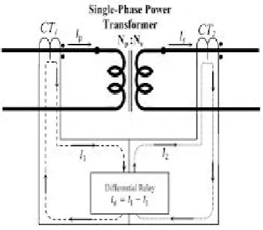
PRINCIPLE OF DIFFERENTIAL PROTECTIONPrinciple of differential protection scheme is one of simple conceptual technique .The differential relay (Figure 1) actually compares between primary current and secondary current of power transformer, if any unbalance found in between primary and secondary current s the relay will actuate and inter trip both the primary and secondary circuit breaker of the transformer. Suppose you have one transformer which has primary rated current Ip and secondary current Is. If you install CT(Figure 2) of ratio Ip/1Aat the primary side and similarly, CT of ratio Is/1A at the secondary side of the transformer. The secondaries of these both CTs are connected together in
such a manner that secondary currents of both CTs will oppose each other. In other words, the secondaries of both CTs should be connected to the same current coil of a differential relay in such an opposite manner that there will be no resultant current in that coil in a normal working condition of the transformer due to which the normal ratio of the transformer disturbed then the secondary current both transformers will not remain the same and one resultant current will flow through the current coil of the differential relay. Which will actuate the relay and inter trip both the primary and secondary circuit breakers.
Figure 1.
Single Phase transformer
Figure 2.
Basic Differential Relay
IV.
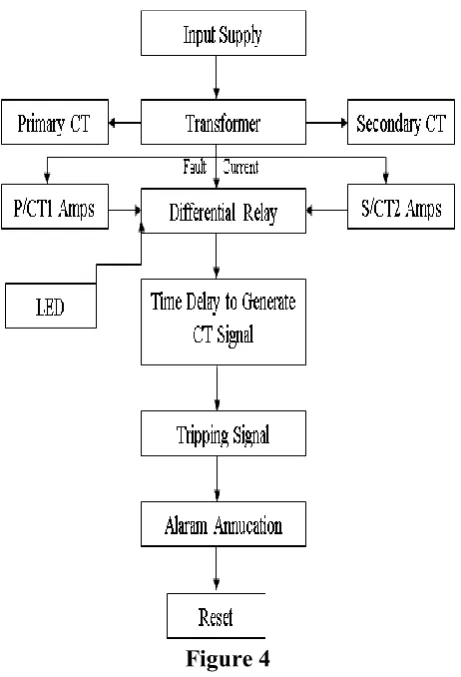
PROPOSED BLOCK DIAGRAM FOR TRANSFORMER PROTECTIONFigure 4
The relay which is used to check the difference between the output and input currents for power system current is known as differential relay. The basic function of this relay working according to the principle of Faraday.s current law. The difference amongst the currents may also be in phase angle or in magnitude or in each.
For hale and energetic operation, angle and magnitude variations must be zero. In case there’s a difference which difference go beyond some value, the relay can work and interconnected electrical fuse can disconnect. How to measure and protect current transformer. Allow us to assume an easy example of an influence power transformer with transformation magnitude ratio relation 1:1 and (y/y) connection and therefore the CT1 and CT2 ensure a similar transformation magnitude relation as shown.
The current flows within the primary side and secondary side of power transformer are equal
presumptuous ideal power transformer. The
secondary current I1 and I2 are same in magnitude and reverse in direction Therefore the net current within the differential is nil at load situation (without any fault), and therefore the relay won’t operate.
Assigning the previous one the power transformer with an external fault is shown. During this case the two currents I1 and I2 can increase to terribly high magnitudes values however there’s no modification in phase angle. Hence net current within the differential coil continues to be zero and therefore the relay won’t operate.
In the same condition internal fault occurs the fault current I1 and I2 are non zero value hence the difference current I1 or I2 whichever is high gives the relay to trip the circuit on both the primary and the secondary sides.
V.
CONCLUSIONBy using this set-up kit we can studied and to understand the basics of terminology in addition of this work The single phase transformer protection by using microcontroller based differential relay was constructed , designed and the function are verified successfully.This objective was achieved effectively and output results are verified practically by using set-up kit
VI.
REFERENCES[1]. Mao P.L and R.K Agarwal,2001. A novel approach to classification of the transient phenomena in power transformers using combined wavelet transform and neural network. IEEE Trans.power Deliv.,16:4
[2]. Sidhu, T.S.,M.S Sachdev and M.Hfuda,1996 computer simulation of protective relay design for evaluation their performance. Power system
Research Group University of
Protection. CRC Press. ISBN 978-0-8247-9911-3.
[3]. Lundqvist, Bertil. "100 years of relay protection, the Swedish ABB relay history"(PDF). ABB. Retrieved 30 December 2015.
[4]. Schossig, Walter (September 2014). "Protection History". Pacworld. Retrieved 30 December 2015.
[5]. Mooney, Joe (March 25–28, 1996).
Microprocessor-Based Transmission Line Relay
Applications. American Public Power
Association's Engineering & Operations Workshop. Salt Lake City, Utah: Schweitzer Engineering Laboratories, Inc. p. 1.
[6]. Silent Sentinels. Newark, New Jersey:
Westinghouse Electric & Manufacturing Company. 1940. p. 3.
[7]. "AEMC - Current Rules". www.aemc.gov.au. Retrieved 2015-12-30.
[8]. "Protection System Maintenance - A Technical Reference" (PDF). www.nerc.com. p. 1. Retrieved 2016-01-05.
[9]. Gadgil, Kaustubh (September 2010). A
Numerical Protection Relay Solution(Technical report). Texas Instruments. SLAA466.
[10]. Mason, C. Russell (January 15, 1956). The Art and Science of Protective Relaying. ISBN 0-471-57552-6.
[11]. Protective Relays Application Guide (Report). London: The General Electric Company (PLC) of England. January 1974.
[12]. Protective Relays Application Guide 3rd Edition, GEC Alsthom Measurements Ltd. 1987, no ISBN, pages 9-10, 83-93
[13]. Warrington, A. R. van C. (1968-01-01). Relay Design and Construction. Springer US. pp. 29– 49. ISBN 978-1-4684-6461-0. doi:10.1007/978-1-4684-6459-7_2.
[14]. IEE (1981). Electricity Council, ed. Power System Protection: Systems and methods. London: Peter Peregrinus. p. 15. ISBN 9780906048535.
[15]. Metha,V.K. & Rohit (July 2008). "Chapter 21". Principles of Power System (4th ed.). S Chand. p. 503.
[16]. Paithankar, Y.G. & Bhide, S.R. (July 2013). Fundamentals of Power System Protection(2nd ed.). PHI Learning. p. 33. ISBN 978-81-203-4123-4.
[17]. Bakshi, U.A. & A.V. (2010). "Chapter 1". Protection of Power System. Technical Publications. p. 16. ISBN 978-81-8431-606-3. [18]. Ram, Badri; Vishwakarma, D.N. (2007) [1994].
Power System Protection and Switchgear. New Dehli: Tata McGraw-Hill..
[19]. Jump up to:a b Rao, T.S Madhava (1989). Power System Protection: Static Relays (2nd ed.). New Dehli: India Professional. ISBN 978-0-07-460307-9.
[20]. Singh, Ravindra P. (2009). Switchgear and Power System Protection. New Dehli: PHI Learning Private Limited. p. 151. ISBN 978-81-203-3660-5.
[21]. Rockefeller, G.D. (1969-04-01). "Fault Protection with a Digital Computer". IEEE Transactions on Power Apparatus and Systems.
PAS-88 (4): 438–464. ISSN 0018-9510.
doi:10.1109/TPAS.1969.292466.
[22]. "PAC World magazine: Interview with George Rockefeller Jr.". www.pacw.org. Retrieved 2016-01-13.
[23]. Rockefeller, G.D.; Udren, E.A. (1972-05-01). "High-Speed Distance Relaying Using a Digital Computer II-Test Results". IEEE Transactions on Power Apparatus and Systems. PAS-91 (3):
1244–1258. ISSN 0018-9510.
doi:10.1109/TPAS.1972.293483.
[24]. "PAC World magazine: Protection History". www.pacw.org. Retrieved 2016-01-13.
[25]. Johns, A. T.; Salman, S. K. (1995-01-01). Digital Protection for Power Systems. IET Digital Library. doi:10.1049/pbpo015e.
microprocessor-based technology applied to relaying (Report). IEEE..
[27]. Singh, L.P. (1997). Digital Protection: Protective
Relaying from Electromechanical to
Microprocessor. New Dehli: New Age
International. p. 4.
[28]. Tziouvaras, Demetrios A.; Hawbaker, William D. (October 1990). Novel Applications of a Digital Relay with Multiple Setting Groups.
17th Annual Western Protective relay
Conference, Spokane,Washington.
[29]. Network Protection & Automation Guide. Levallois-Perret, France: Alstom. 2002. ISBN 2-9518589-0-6.
[30]. Khan, Z.A; Imran, A. (2008-03-01). "Algorithms and hardware design of modern numeric overcurrent and distance relays". Second
International Conference on Electrical
Engineering, 2008. ICEE 2008: 1–5.
doi:10.1109/ICEE.2008.4553897.
[31]. Sham, M.V.; Vittal, K.P. (2011-12-01). "Development of DSP based high speed numerical distance relay and its evaluation using hardware in loop power system simulator". Innovative Smart Grid Technologies - India (ISGT India), 2011 IEEE PES: 37–42. doi:10.1109/ISET-India.2011.6145351.
[32]. Henderson, Brad (17 March 2009). Protection relay settings management in the modern world (PDF). South East Asia Protection and Automation Conference -CIGRE Australia Panel B5. p. 2. Retrieved 2016-01-05.
[33]. Hewitson, L.G.; Brown, M. (2005). Practical Power System Protection. Elsevier {BV}. ISBN 978-0750663977.
[34]. Instruction Manual Overcurrent Protection Relay GRD110 (PDF). Japan: Toshiba. 2010.
[35]. Paithankar, Y.G; Bhinde, S.R. (2003).
Fundamentals of Power System protection. New Dehli: Ashok K Goshe. ISBN 81-203-2194-4. [36]. Warrington, A.R.van C. (1968). Protective
Relays: Their Theory and Practice Volume One.