IJEDR1904016 International Journal of Engineering Development and Research (www.ijedr.org) 77
effect of friction factor on process and design
parameters in spiral flow using design of experiment
and CFD simulation technique
1Lokesh Singh, 2A.K. Raghav 1Research Scholar, 2Professor
1Career Point University, 2career Point University
_____________________________________________________________________________________________________
Abstract - Spiral tubes are widely used in various engineering applications like heat transfer among various fluids,
refrigeration applications and many more. The optimum spiral tube can improve efficiency of the system. So various research is carried out on spiral tubes design and process parameters in previous decades. In present paper effect of friction factor is studied for spiral tube by chaining its process and design parameters. The present study is based on CFD simulation technique. Experiments are designed using “Taguchi Method”. The three process parameters which are identified for this study is wall temperature of surface, fluid inlet temperature and mass flow rate of fluid. Three design parameter which are selected for this study are inner diameter of tube, pitch of tube and curvature ratio of tube. Total six parameters are selected and then experiment table is generated using Taguchi method and 36 experiments are generated which are then simulated using Ansys Fluent (Version 14.5) software. Experiment validation is performed using previous experiment work on spiral tube. Friction factor is response parameter selected for this study and the analysis is performed using Signal to noise ratio parameter. To improve the effect of pressure-drop or decrease the friction factor in spiral tube the most reliable parameter is inner diameter of tube and least parameter is wall temperature of tube. Pitch is another important parameter for friction factor analysis.
keywords - Spiral Tube, CFD simulation, Design of Experiment, Taguchi Method, Signal To Noise Ratio, Friction Factor
_____________________________________________________________________________________________________
INTRODUCTION
Fierce flow and convective heat move in a spirally coiled tube are convoluted as looking at the straight tube. This is on the grounds that the heat moves and flow improvements in the bended tube emphatically rely upon the conduct of auxiliary flow. The optional flow in the bended tube is caused by the radial power. Helical and spiral coils are well known sorts of bended tubes which have been utilized in a wide assortment of utilizations. Be that as it may, most examinations for bended tubes are worried about the helically coiled heat exchanger [1] and [2] tentatively considered on the natural convection heat move from helical coiled tubes in water. The anticipated outlet temperature was analyzed with the deliberate qualities from an exploratory arrangement. [3] thought about impact of tube ebb and flow proportion on the habitation time appropriation of various particles in helical tubes. The majority of the parameters, aside from the transporter liquid thickness affected the flow conduct of particles. [4] gathered the environmental dampness from a nonstop wind stream through a refrigerated coil tube. [5,6] considered entropy age, thermodynamics and Reynolds number improvements of completely created laminar convection in a helical coil with consistent heat transition. In their third and fourth papers, [7,8] broke down the ideal mass flow rate and shape proportion for completely created laminar constrained convection in a helical coiled tube with consistent heat transition in light of negligible entropy age standard. Air and water were utilized as working liquids. [9] tentatively examined impacts of diffusive increasing speed on the flow system map and the spatial and the fleeting flow structure appropriation of air–water two-stage flow in helically coiled tubes. Contrasted with the various examinations in the helically coiled tubes, there are not many specialists on the heat move in the spiral-coil heat exchangers as in open writing. [10,11] utilized the pertinent connections of the tube-side and air-side heat move coefficients in the recreation to decide the warm presentation of the spiral-coil heat exchanger under cooling and dehumidifying conditions. [12] numerically considered the cooling a liquid flowing through a spiral coil submerged in a chilled water compartment. A basic axisymmetric numerical technique was depicted to decide the temperature of the liquid in the spiral coil and that of the coil surface.
Objective of Study
The prime aim of this research is to find the role of friction factor in spiral flow using CFD simulation technique for process and design parameters. The experiments are plan to design using Taguchi method. The selection of parameters is purely on literature review. Signal to Noise ratio is used to identify the ranks among input parameters and nonlinear model equation for friction factor is also in scope of this research study.
Base Design of Spiral Tube and Validation with CFD simulation
IJEDR1904016 International Journal of Engineering Development and Research (www.ijedr.org) 78 is used for validation of CFD simulation. The experimental validation for pressure drops for selective spiral tube for this research paper. The Experiment validation for pressure drop is present in table 1 and fig. 1.
Table 3.9
Table1 Experimental validation with previous research work [01, 02] for Pressure Drop
MFR
Experiment (Tin=20 C and THS=35
C) Simulation (Tin=20 C and THS=36 C)
Straight CR-0.02 CR-0.04 CR-0.05 Straight-S CR-0.02-S CR-0.04-S CR-0.05-S
0.050 0.99 1.90 1.53 1.51 1.11 2.09 1.76 1.81
0.066 1.92 2.83 2.83 2.73 2.08 3.14 3.04 3.24
0.085 3.20 4.34 4.34 4.26 3.45 4.82 5.00 4.80
0.100 4.71 6.24 6.24 5.84 4.80 7.12 6.77 6.24
0.117 6.39 8.02 8.02 7.82 6.86 9.05 8.94 8.32
Table 2 Error in experimental validation Pressure Drop [01, 02]
Error (Tin=20 C and THS=36 C)
Straight-S Cr-0.02-S Cr-0.04-S Cr-0.05-S
12.1 10.0 15.0 19.9
8.4 10.8 7.3 18.5
7.7 11.1 15.3 12.7
2.0 14.1 8.5 6.8
7.3 12.8 11.5 6.4
Figure 1 Experiment Validation for Pressure Drop [01, 02]
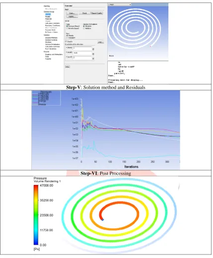
CFD Simulation Modeling Steps
As show in figure 1, the proper experiment validation is performed for this selective research paper. After validation of spiral tube, the proper modeling steps used for this research study is present in this section and detailed steps are present in table 2 for CFD simulation using Ansys Fluent Software (Version 14.5)
IJEDR1904016 International Journal of Engineering Development and Research (www.ijedr.org) 79 Step-II: Named Boundary Selection
Step-III: Meshing of CFD Domain
IJEDR1904016 International Journal of Engineering Development and Research (www.ijedr.org) 80 Step-V: Solution method and Residuals
Step-VI: Post Processing
Factor and Levels
As present in objective of the research work, the selective process and design parameters for spiral flow study is present in table 3 and table 4 with proper levels. The selection of levels is done with help of previous published research work.
Table 3 Process parameter and their levels
Factors Short Discription Level-I Level-II Level-III Unit
Inner Diameter ID 8 9 NA mm
Mass Flow Rate MFR 0.1 0.12 0.14 kg/sec
Heat Flux (Twall) HF 30 33 36 C
Table 4 Design parameter and their levels
Factors Short Discription Level-I Level-II Level-III Unit
Fluid Temperature FT 15 17 19 C
Pitch Pitch 25 30 35 mm
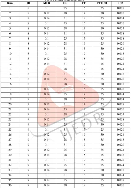
IJEDR1904016 International Journal of Engineering Development and Research (www.ijedr.org) 81 Mixed Orthogonal Array
Taguchi method is selected for the present study using Minitab software for making this experiment table. The experiments are then numerically solved by using CFD simulation software. Total 36 cases are designed for this research work. The primary parameter pressure is simulated using Ansys Fluent software. The experiment table is present in table 5.
Table 5 Mixed orthogonal Array
Run ID MFR HS FT PITCH CR
1 8 0.1 25 15 25 0.018
2 8 0.12 28 17 30 0.020
3 8 0.14 31 19 35 0.024
4 8 0.1 25 15 25 0.020
5 8 0.12 28 17 30 0.024
6 8 0.14 31 19 35 0.018
7 8 0.1 25 17 35 0.018
8 8 0.12 28 19 25 0.020
9 8 0.14 31 15 30 0.024
10 8 0.1 25 19 30 0.018
11 8 0.12 28 15 35 0.020
12 8 0.14 31 17 25 0.024
13 8 0.1 28 19 25 0.024
14 8 0.12 31 15 30 0.018
15 8 0.14 25 17 35 0.020
16 8 0.1 28 19 30 0.018
17 8 0.12 31 15 35 0.020
18 8 0.14 25 17 25 0.024
19 9 0.1 28 15 35 0.024
20 9 0.12 31 17 25 0.018
21 9 0.14 25 19 30 0.020
22 9 0.1 28 17 35 0.024
23 9 0.12 31 19 25 0.018
24 9 0.14 25 15 30 0.020
25 9 0.1 31 17 25 0.020
26 9 0.12 25 19 30 0.024
27 9 0.14 28 15 35 0.018
28 9 0.1 31 17 30 0.020
29 9 0.12 25 19 35 0.024
30 9 0.14 28 15 25 0.018
31 9 0.1 31 19 35 0.020
32 9 0.12 25 15 25 0.024
33 9 0.14 28 17 30 0.018
34 9 0.1 31 15 30 0.024
35 9 0.12 25 17 35 0.018
36 9 0.14 28 19 25 0.020
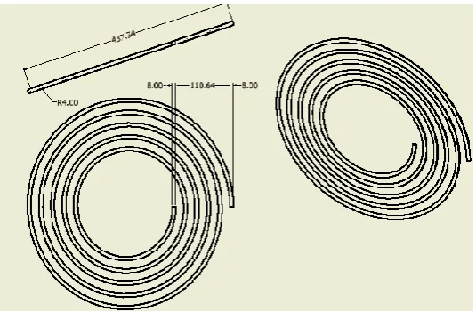
IJEDR1904016 International Journal of Engineering Development and Research (www.ijedr.org) 82 Figure 2 Dimension of spiral tube used in present research study
Result and Discussion
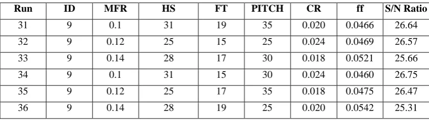
The final table of friction factor for 36 cases are present in table 6 with friction factor and S/N ratio calculation for each experiment using S/N ratio log formula.
Table 6 S/N ratio calculation for friction factor
Run ID MFR HS FT PITCH CR ff S/N Ratio
1 8 0.1 25 15 25 0.018 0.0519 25.69
2 8 0.12 28 17 30 0.020 0.0400 27.96
3 8 0.14 31 19 35 0.024 0.0387 28.24
4 8 0.1 25 15 25 0.020 0.0492 26.16
5 8 0.12 28 17 30 0.024 0.0366 28.74
6 8 0.14 31 19 35 0.018 0.0375 28.52
7 8 0.1 25 17 35 0.018 0.0421 27.52
8 8 0.12 28 19 25 0.020 0.0451 26.91
9 8 0.14 31 15 30 0.024 0.0403 27.90
10 8 0.1 25 19 30 0.018 0.0463 26.69
11 8 0.12 28 15 35 0.020 0.0342 29.32
12 8 0.14 31 17 25 0.024 0.0402 27.92
13 8 0.1 28 19 25 0.024 0.0473 26.50
14 8 0.12 31 15 30 0.018 0.0421 27.52
15 8 0.14 25 17 35 0.020 0.0329 29.65
16 8 0.1 28 19 30 0.018 0.0468 26.60
17 8 0.12 31 15 35 0.020 0.0367 28.72
18 8 0.14 25 17 25 0.024 0.0400 27.97
19 9 0.1 28 15 35 0.024 0.0438 27.16
20 9 0.12 31 17 25 0.018 0.0572 24.86
21 9 0.14 25 19 30 0.020 0.0471 26.54
22 9 0.1 28 17 35 0.024 0.0488 26.23
23 9 0.12 31 19 25 0.018 0.0572 24.86
24 9 0.14 25 15 30 0.020 0.0483 26.33
25 9 0.1 31 17 25 0.020 0.0583 24.68
26 9 0.12 25 19 30 0.024 0.0445 27.03
27 9 0.14 28 15 35 0.018 0.0458 26.79
28 9 0.1 31 17 30 0.020 0.0512 25.81
29 9 0.12 25 19 35 0.024 0.0479 26.39
IJEDR1904016 International Journal of Engineering Development and Research (www.ijedr.org) 83
Run ID MFR HS FT PITCH CR ff S/N Ratio
31 9 0.1 31 19 35 0.020 0.0466 26.64
32 9 0.12 25 15 25 0.024 0.0469 26.57
33 9 0.14 28 17 30 0.018 0.0521 25.66
34 9 0.1 31 15 30 0.024 0.0460 26.75
35 9 0.12 25 17 35 0.018 0.0475 26.47
36 9 0.14 28 19 25 0.020 0.0542 25.31
Rank Identification of friction factor for Spiral Flow
S/N ratio present in table 6 is used to find the rank among all factors for friction factor response and the final results for ff is present in table 7 with all ranks among factors. It is also show in fig. 3 for S/N ratio of ff response variable.
Table7 Rank identification for friction factor
Level ID MFR HS FT PITCH CR
1 27.7 26.37 26.92 26.97 26.01 26.32
2 26.04 27.11 26.82 26.96 26.96 27
3 27.13 26.87 26.68 27.64 27.28
Delta 1.65 0.76 0.09 0.28 1.62 0.96
Rank 1 4 6 5 2 3
Figure 3 S/N ratio for friction factor (ff)
As seen in table 7, the first rank of factor is inner diameter of tube, second rank is for Pitch, third rank is set for curvature ratio (CR), fourth and fifth ranks are set for mass flow rate and inlet temperature of fluid and last rank is set for wall temperature of surface of spiral tube.
Optimal Solution Calculation for ff
The single response optimization is present in table 8 for friction factor and full detailed calculation is also present in this section for this response variable.
Table 8 Optimal Solution for friction factor (ff)
Response ID MFR HS FT PITCH CR ff
ff 8 0.14 25 15 35 0.024 0.0267
The formula is following:
R
F
D
Ln
C
Ln
B
Ln
A
response
=
+
+
+
Ln−
(
−
1
)
IJEDR1904016 International Journal of Engineering Development and Research (www.ijedr.org) 84 Predicted value for Friction Factor (ff)
ff
CR
PITCH
FT
HS
MFR
ID
ff
=
8+
0.14+
25+
15+
35+
0.024−
5
*
Where ff is average of friction factor = 0.0458 ID is average value of factor ID for 8 mm = 0.0415 MFR is average value of factor MFR for 0.14 kg/s= 0.0383 HS is average value of factor HS for 25 C is = 0.0452 FT is average value of factor FT for 15 C is = 0.0453
PITCH is average value of factor PITCH for value 35 mm=0.0419 CR is average value of factor CR for value 0.024 mm=0.0434 Substituting the values of various terms in the above equation,
0267
.
0
0458
.
0
*
5
0434
.
0
0419
.
0
0453
.
0
0452
.
0
0383
.
0
0415
.
0
*
5
024 . 0 35 15 25 14 . 0 8=
−
+
+
+
+
+
=
−
+
+
+
+
+
=
ff
ff
ff
CR
PITCH
FT
HS
MFR
ID
ff
Non-Linear Model Equation for ff
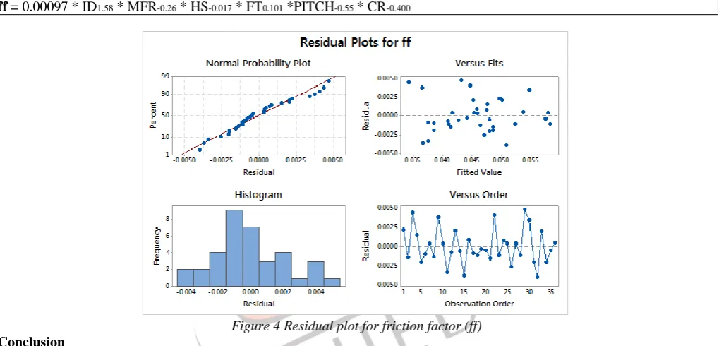
ff = 0.00097 * ID1.58 * MFR-0.26 * HS-0.017 * FT0.101 *PITCH-0.55 * CR-0.400
Figure 4 Residual plot for friction factor (ff)
Conclusion
Three process and three design parameters are used for spiral tube flow analysis using CFD simulation and DOE technique. Total 36 cases are designed for this present research study. The final conclusion of the study is that the both type of parameters effect on the friction factor of spiral tube but most effective parameter is inner diameter of spiral tube and least important parameter is wall temperature of spiral tube. Pitch and CR are also play important role on this spiral tube flow for friction factor.
References
[1] NAPHON P., SUWAGRAI J. Effect of curvature ratios on the heat transfer and flow developments in the horizontal spirally coiled tubes[J]. International Journal of Heat and Mass Transfer, 2007, 50(3-4): 444-451.
[2] NAPHON P. Study on the heat transfer and flow characte- ristics in a spiral-coil tube[J]. International Communica- tions in Heat and Mass Transfer, 2011, 38(1): 67-74.
[3] A. Cioncolini, L. Santini, An experimental investigation regarding the laminar to turbulent flow transition in helically coiled pipes, Exp. Ther. Fluid Sci. 30 (2006) 367–380.
[4] WONGWISES S., NAPHON P. Heat transfer characteri- stics of a spirally coiled, finned-tube heat exchanger under dry-surface conditions[J]. Heat Transfer Engineering, 2006, 27(1): 25-34.
[5] JI Jia-dong, GE Pei-qi and BI Wen-bo. Numerical analysis on flow-induced vibration responses of elastic tube bundle[J]. Journal of Vibration and Shock, 2016, 35(6): 80-84(in chinese).
[6] LI Cheng-guang, XUE Wan-yun and HUAI Wen-xin. Effect of vegetation on flow structure and dispersion in strongly curved channels[J]. Journal of Hydrodynamics, 2015, 27(2): 286-291.
[7] ZACHÁR A. Analysis of coiled-tube heat exchangers to improve heat transfer rate with spirally corrugated wall[J]. International Journal of Heat and Mass Transfer, 2010, 53(19-20): 3928-3939.
IJEDR1904016 International Journal of Engineering Development and Research (www.ijedr.org) 85 [9] YAN Ke, GE Pei-qi and BI Wen-bo et al. Characteristics of fluid-structure interaction of conical spiral tube bundle with FEM[J]. Journal of Hydrodynamics, 2010, 22(1): 121-128.
[10] Vijiapurapu, S., Cui, J., Simulation of Turbulent Flow in a Ribbed Pipe Using Large Eddy Simulation, Numerical Heat Transfer, Part A, 51 (2007), 12, pp. 1137–1165.
[11] Bernhard, D., Hsieh, C., Pressure Drop in Corrugated Pipes, Journal of Fluids Engineering, 118 (1996), 2, pp. 409–410. [12] Taylor, J. et al., Characterization of the Effect of Surface Roughness and Texture on Fluid Flow - Past, Present and Future, International Journal of Thermal Sciences, 45 (2006), 10, pp. 962–968.
![Figure 1 Experiment Validation for Pressure Drop [01, 02]](https://thumb-us.123doks.com/thumbv2/123dok_us/8188044.1367493/2.595.87.510.74.578/figure-experiment-validation-pressure-drop.webp)