INTERACTING WITH NETWORKED DEVICES
Olufisayo Omojokun
A dissertation submitted to the faculty of the University of North Carolina at Chapel Hill in partial fulfillment of the requirements for the degree of Doctor of Philosophy in the Department of Computer Science.
Chapel Hill 2006
Approved by Advisor: Prasun Dewan
Reader: Charles Isbell Reader: Ketan Mayer-Patel Reader: Maria Papadopouli
ii
iii
ABSTRACT
OLUFISAYO OMOJOKUN: Interacting with Networked Devices (Under the direction of Prasun Dewan)
Networking technology has become applicable in domains beyond the conventional computer. One such domain currently receiving a significant amount of research attention is networking arbitrary devices such as TVs, refrigerators, and sensors. In this dissertation, we focus on the following question: how does an infrastructure deploy a user-interface for a single device or a composition of several ones?
We identify and evaluate several deployment approaches. The evaluation shows the approach of automatically generating device user-interfaces ‘on the fly’ as particularly promising since it offers low programming/maintenance costs and high reliability. The approach, however, has the important limitation of taking a long time to create a user-interface. It is our thesis that it is possible to overcome this limitation and build graphical and speech user-interface generators with deployment times that are as low as the inherently fastest approach of locally loading predefined code. Our approach is based on user-interface retargeting and history-based generation. User-interface retargeting involves dynamically mapping a previously generated user-interface of one device to another (target) device that can share the user-interface. History-based generation predicts and presents just the content a user needs in a device’s user-interface based on the user’s past behavior. By filtering out unneeded content from a screen, it our thesis that history-based generation can also be used to address the issue of limited screen space on mobile computers.
iv
v
ACKNOWLEDGEMENTS
I am deeply grateful to several people who have helped me throughout my years as a graduate student. First is my advisor, Professor Prasun Dewan, whose guidance, support, and encouragement allowed me to complete my thesis. I also want to thank the other members of my thesis committee, Professor Charles Isbell, Professor Maria Papadopouli, Professor Ketan Mayer-Patel, Professor David Stotts, Professor Richard Han, and Professor Amin Vahdat for their valuable comments and suggestions.
I would like to thank my parents for their loving support during all my years in and before graduate school. I additionally recognize my two brothers and two sisters for their emotional support during stressful times.
vi
TABLE OF CONTENTS
Page
Chapter 1: Introduction ...1
Benefits of Deploying Software-based User-Interfaces ...3
1.2 Deploying Single Device User-Interfaces ...8
1.3 Deploying Multi-Device User-Interfaces ...11
1.4 Thesis ...14
1.5 Summary ...14
Chapter 2: Related Work ...16
2.1 Deploying Single Device User-Interfaces ...16
2.1.1 Palm/Pocket-PC IR Control Programs ...18
2.1.2 Jini (Service UI Approach) ...19
2.1.3 MOCA...20
2.1.4 Cooltown...20
2.1.5 Universal Plug and Play (UPnP)...20
2.1.6 ObjectEditor...21
2.1.7 Hodes’ System ...22
2.1.8 Personal Universal Controller (PUC)...23
2.1.9 ICrafter...24
2.2 Deploying Multi-Device User-Interfaces ...25
2.2.1 Cougar and TinyDB...26
2.2.2 Hodes’ System ...27
vii
2.2.4 WebSplitter ...29
2.2.6 Speakeasy...34
Chapter 3: Analysis of Various Approaches...36
3.1 Overview of Metrics and Setup ...36
3.2 User-Interface Flexibility...39
3.3 Programming Costs...46
3.4 Maintenance Costs ...49
3.4.1 Predefined vs. Generation...49
3.4.2 Client-Factory and Third-Party Factories vs. Other Approaches ...49
3.5 Efficiency...50
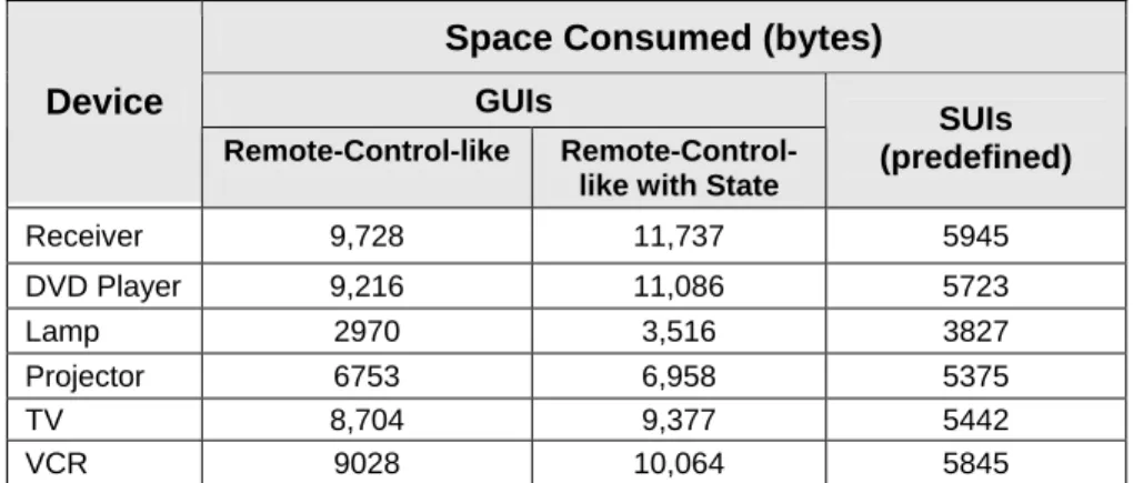
3.5.1 Space Costs ...51
3.5.2 Deployment Time Costs ...52
3.5.3 Operation Invocation Time Costs ...63
3.6 Device Binding Time ...64
3.7 Deployment Reliability...64
3.8 Conclusion ...65
Chapter 4: User-Interface Retargeting ...69
4.1 Overview...70
4.2 GUI Retargeting...74
4.3 SUI Retargeting ...91
4.4 Evaluation ...92
4.4.1 Source User-interface Selection Performance ...95
4.4.2 Approach Selection Performance ...97
4.4.3 Retargeting Performance ...98
viii
Chapter 5: History-based Generation...113
5.1 Approach...114
5.2 Evaluation ...117
5.2.1 Generation Time Efficiency...118
5.2.2 Screen Space Efficiency ...123
5.3 Conclusion ...124
Chapter 6: Pattern-based Composition ...125
6.1 Overview...126
6.2 Algorithms and Evaluation ...136
6.2.1 ‘GUI Stack’ Composer ...137
6.2.2 ‘GUI Merge’ Composer...138
6.2.3 ‘Do Sequence’ Composer ...140
6.2.4 ‘Do All’ Composer ...142
6.2.5 Query Composer...144
6.2.6 ‘Data Transfer’ Composer...146
6.2.6 ‘Conditional Connect’ Composer ...149
6.3 Conclusion ...152
Chapter 7: User-Based Composition ...153
7.1 ML Approach...155
7.2 Experiments ...156
7.3 Evaluation ...158
7.3.1 Completeness ...159
7.3.2 Task-based Grouping ...160
7.3.3 ‘Do Sequence’ Discovery ...162
ix
x
LIST OF TABLES
Table 1. An example composer registry...31
Table 2. An example composer registry...31
Table 3. Number of lines of user-interface code used for each device ...48
Table 4. Amount of space consumed by the code of each device’ handcrafted user-interface...52
Table 5. Retargeting flexibility – Hodes’ System vs. Our Goals. ...74
Table 6. A summary of our 11 participants...94
Table 7. An evaluation of Tret‘s ability to predict the fastest command-only user-interface to retarget. {* The DVD player also serves as a music CD player} ...97
Table 8. An evaluation of Tret‘s ability to predict the fastest command-and-state based user-interface to retarget. {* The DVD player also serves as a music CD player} ..97
Table 9. For command-only UI deployment, a comparison of the approach predicted to be the fastest to the approach that actually measures to be the fastest...98
Table 10. For command-and-state based UI deployment, a comparison of the approach predicted to be the fastest to the approach that actually measures to be the fastest....98
Table 11. Number of screens consumed by each device’s command-only GUI. ...114
Table 12. A summary of command filtering amounts for each device. ...120
Table 13. Number of commands required in each participant’s set of history-based user-interfaces. ...122
Table 14. The number of Ipaq screens required for full and history-based GUI. ...123
Table 15. A classification of existing systems ...130
Table 16. A count of each participants missed buttons...159
xi
LIST OF FIGURES
Figure 1. (a) The author controlling a TV, VCR, and projector; (b) An adhoc
security-system composition consisting of a motion sensor and stereo... 3
Figure 2. (a) Left, a VCR’s on-board controls; (b) Right, a Traditional IR Remote. ... 4
The mobile computer approach, illustrated above, offers several additional benefits: ... 4
Figure 3. Two possible approaches to UI deployment: (a) deploying a UI from pre-installed code and (b) generating a UI. ... 9
Figure 4. A generated receiver user-interface on an Ipaq. ... 10
Figure 5. A depiction of cell phone (Motorola i710) and Pocket PC (Compaq Ipaq) screen size differences. The cell phone’s screen is less than half of the Ipaq’s... 11
Figure 6. A conceptual view of how a pattern-based composer could query several sensors. ... 13
Figure 7. The general architecture abstracts existing infrastructures for deploying for single device UIs ... 16
Figure 8. Current UI deployment approaches... 17
Figure 9. The IR port on the front end of the Ipaq for transferring data and controlling IR devices... 18
Figure 10. A TV user-interface created using OmniRemote[2]... 19
Figure 11. A CD player HTML-based user-interface inside a Netscape Browser. ... 20
Figure 12. A depiction of how ObjectEditor works... 22
Figure 13. A lamp UI generated by Hodes’ System [15, 16]... 23
Figure 14. A portion of a stereo system user-interface generated by PUC [27]. Notice the cassette navigation buttons are specifically grouped together. ... 24
Figure 15. (left) the HTML generated for setting a projector input; (right) the rendered web page[28]. ... 25
Figure 16. Two possible ways to organize composers... 26
Figure 17. A compound UI for a set of lights. ... 28
xii
Figure 19. A lights composition... 30
Figure 20. An example composer registry. ... 31
Figure 21. (left) a Celadon PIC Link IR module (right) an X10 FireCracker CM17A module... 37
Figure 22. Sample programming interfaces (for the receiver and lamp). ... 38
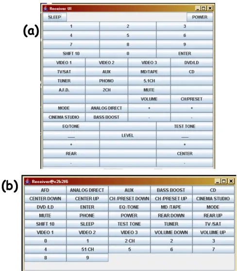
Figure 23. Command-only receiver GUIs written using Java Swing: (a) a predefined GUI that mimics the device’s remote control and (b) a GUI generated fully automatically by ObjectEditor. ... 40
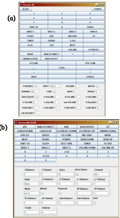
Figure 24. Command and state-based receiver GUIs: (a) predefined GUI and (b) generated by ObjectEditor fully automatically. ... 42
Figure 25. A depiction of our experimental SUI generator. ... 45
Figure 26. UI generation vs. the predefined approach... 47
Figure 27. The downloaded components of the factory and generation approaches... 54
Figure 28. Command-only GUI deployment times for all six devices (using the laptop, ObjectEditor preloaded in memory, and a wired LAN connection). ... 56
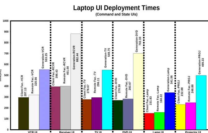
Figure 29. Command-and-state based GUI deployment times for all six devices (using the laptop, ObjectEditor preloaded in memory, and a wired LAN connection). ... 57
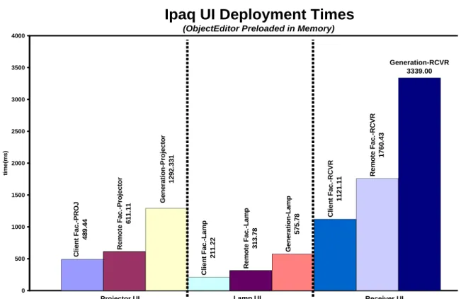
Figure 30. Command-and-state based GUI deployment times for the projector, lamp, and receiver (using the Ipaq and a wired LAN connection). ... 58
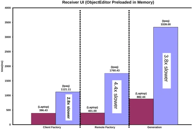
Figure 31. A visual display of the significant differences between Ipaq and laptop GUI deployment ... 59
Figure 32. Command and state based receiver GUI deployment times using the laptop and different network speeds. ... 60
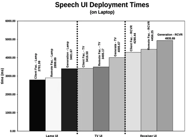
Figure 33. Command-only SUI deployment times for the projector, lamp, and receiver (using the Laptop and a wired LAN connection)... 62
Figure 34. A graphical representation of the unique benefit(s) of each approach. ... 68
Figure 35. Retargeting a UI between two lights on different floors. ... 69
Figure 36. Retargeting between two lights in different rooms under Hodes’ System. .... 70
xiii
Figure 38. User-interfaces requiring different levels of source user-interface flexibility.
... 71
Figure 39. Devices with identical programming interfaces share identical
user-interfaces. ... 72
Figure 40. Retargeting between a dimmable and non-dimmable lamp. ... 73
Figure 41. Two different VCR programming interfaces that can share the same UI. ... 73
Figure 42. The maximum N value for Tadd_btn comes from retargeting a light UI to a
receiver. ... 81
Figure 43. A depiction of part of our profiling experiments: (a) finding the time it takes
to add 4 buttons to an empty UI, (b) finding the time it takes to remove 4 buttons from a UI, and (c) finding the time it takes to remap 4 buttons on a UI. ... 82
Figure 44. The time it takes to add new buttons to an empty GUI (slow vs. fast laptop).
... 83
Figure 45. The time it takes to add new property widgets to an empty GUI (slow vs. fast
laptop) The dashed lines correspond to the slow laptop and the bold lines correspond to the fast laptop. ... 83
Figure 46. The time it takes to remove pre-existing property widgets on a GUI (slow vs.
fast laptop)... 84
Figure 47. The time it takes to remap pre-existing property widgets on a UI (slow vs. fast
laptop) ... 84
Figure 48. A graph illustrating time differences between the three clients. It also shows
that widgets representing different types can yield different operation times—
particularly on the Ipaq. ... 85
Figure 49. The differences between adding, removing, and remapping a property widget.
... 86
Figure 50. Our tool for automatically recording device interactions at a person’s home.
... 92
Figure 51. A close up of the IRman serial port device. ... 93
Figure 52. The conference room we used. ... 95
Figure 53. Homogeneous retargeting of command-and-state GUIs using the fast laptop
xiv
Figure 54. Homogeneous retargeting of command-only SUIs using the fast laptop and
wired LAN connection. ... 101
Figure 55. A graph comparing the homogeneous retargeting times the to the
corresponding times of competing approaches (using the Ipaq and a 100Mbps
connection). ... 102
Figure 56. Heterogeneous retargeting of command-only GUIs vs. competing approaches
(using the fast laptop and a wired LAN connection). ... 104
Figure 57. Retargeting times of command-and-state based GUIs vs. the corresponding
times of competing approaches (using the fast laptop and a wired LAN connection). ... 104
Figure 58. Retargeting times of command-and-state based GUIs vs. the corresponding
times of competing approaches (using the Ipaq and a wired LAN connection). ... 105
Figure 59. Retargeting times of the receiver command-and-state based GUI vs. the
corresponding times of competing approaches (using the fast laptop and dialup connection). ... 106
Figure 60. Cache-based retargeting times of the command-only GUIs vs. the
corresponding times of competing approaches (using the fast laptop and wired LAN). ... 107
Figure 61. Cache-based retargeting times of the command-and-state based GUIs vs. the
corresponding times of competing approaches (using the fast laptop and wired LAN). ... 108
Figure 62. Cache-based retargeting times of the command-and-state based GUIs vs. the
corresponding times of competing approaches (using the Ipaq and wired LAN).... 108
Figure 63. Cache-based retargeting times of the receiver command-and-state based GUI
vs. the corresponding times of competing approaches (using the fast laptop and dialup connection). ... 110
Figure 64. An entire receiver GUI (left) vs. a receiver GUI containing all of the
commands the owner (author) typically needs (right). ... 113
Figure 65. Number of usage days required for the participants to complete their common
tasks on their respective devices. ... 116
Figure 66. History-based GUI generation performance using the laptop and wired LAN
connection. ... 119
Figure 67. History-based GUI generation performance using the Ipaq and wired LAN
xv
Figure 68. History-based SUI generation performance using the laptop and wired LAN
connection. ... 121
Figure 69. The receiver’s history-based GUI on a single Ipaq screen. With the available space from filtering buttons, the remaining buttons can be stretched to fill the screen. ... 124
Figure 70. Extracting the state and operations from a lamp’s programming interface.. 136
Figure 71. A stacked GUI for watching movies—based on the author’s TV, DVD player, and receiver. ... 138
Figure 72. A GUI for selecting desired buttons for a target task. ... 140
Figure 73. A GUI for creating a ‘watch a DVD’ button. ... 142
Figure 74. A ‘do all’ GUI for a set of lamps... 143
Figure 75. An example GUI for querying rainfall sensors with several attributes. ... 145
Figure 76. A data transfer GUI for cameras and display devices. ... 149
Figure 77. A ’conditional connect’ GUI for creating the adhoc lamps and motion detector security system. ... 151
Figure 78. Our setup containing the participants’ remote, several blank sheets (screens), and button squares... 157
Figure 79. The three user-interfaces that P5 created... 158
Figure 80. A projection of P6’s clusters ... 161
Chapter 1: Introduction
Networking technology has become applicable in domains beyond the conventional computer. One such domain currently receiving a significant amount of research attention is networking arbitrary devices such as TVs, refrigerators, and sensors. There are a number of compelling reasons that make this idea desirable.
One reason is that with a network connection, a device can enhance some general functionality that it already provides. To illustrate, today’s DVD players are capable of showing extra feature content about a movie. Such content is ‘burned’ on a DVD when it is released. With a network connection, a DVD player could possibly connect to a movie producer’s server and download additional content that consists of interesting information that develops after a DVD is released. This ability could be particularly useful in the case of documentaries, which contain facts and data that may become outdated.
Another related reason for networking a device is to allow it to offer totally new functionality that would otherwise be impossible. Consider the following example that has captured the imagination of many: a refrigerator with built-in sensors that could allow it to discover when certain important food items are nearly finished or expired. With a network connection, the refrigerator could notify its owner, who is away from home, to purchase new food. Even more complex, it could connect to the server of the nearest grocery store and order new food. The owner could simply pick the order up and avoid actual shopping [23].
2
design improvements. The networked refrigerator from earlier could, for example, notify its manufacturer of the number of times its doors are opened. Its manufacturer could use this information when designing durable door hinges for future refrigerators. Other parties beyond device manufacturers might find it useful to access logs of user-device interaction. For example, advertisers may want to use logs from remotely loggable TV sets to learn the typical program watching habits of a population of people. Given such information, they can predict the most opportunistic times to place ads and later find an approximate number of likely viewers.
Networking devices can also allow for new and different ways for users to interact/control them. For example, it can allow users to interact with devices using software-based user-interfaces deployed on mobile computers. Figure 1a demonstrates such a case by showing the author using an HP680 Jornada handheld computer to interact with a networked TV, VCR, and projector in a classroom.
It is possible to create software-based user-interfaces for single devices and for combinations of them. A single-device user-interface allows users to control and possibly view the state of a single networked device. For example, it could allow a person driving home on a hot day to use a cell phone to set the thermostat level of the house’s air-conditioning system so that the temperature is cool before getting there. It could also allow the driver to set a TiVo box at home to record an upcoming TV show if there is heavy traffic on the road.
3
completing a given task involving the devices than what is provided by using their individual controls. Another reason is to form a composite unit that provides functionality that the individual devices cannot achieve separately. A stereo and several motion detectors in a house, for example, could be composed together to form an ad hoc security system (Figure 1b). When a detector senses motion, it triggers the stereo to blast music. The same motion detectors could coordinate with various cameras around the house so that any sensed motion triggers the nearest camera to snap pictures of a possible intruder. As the person moves around, other cameras are triggered.
Figure 1. (a) The author controlling a TV, VCR, and projector; (b) An adhoc
security-system composition consisting of a motion sensor and stereo.
In this dissertation, we are particularly interested in the ability to interact with individual devices and their compositions by using software-based user-interfaces deployed on mobile computers. This ability, itself, has many benefits.
Benefits of Deploying Software-based User-Interfaces
Today, it is possible to interact with devices by using hardware-based user-interfaces. Examples of such user-interfaces are on-board and traditional remote controls. On-board controls require users to be within arms reach of the devices they wish to control (Figure 2a). However, it may not always be possible to reach a device. For instance, a presenter
motion detected!
)
)
)
)
)
)
stereo blasts! motion detected!
)
)
)
)
)
)
stereo blasts! motion detected!
)
)
)
)
)
)
stereo blasts!
(a)
(b)
motion detected!
)
)
)
)
)
)
stereo blasts! motion detected!
)
)
)
)
)
)
stereo blasts! motion detected!
)
)
)
)
)
)
stereo blasts!
(a)
4
may not be able to reach a projector mounted on a high ceiling. Traditional infrared (IR) and X10 remote controls address this limitation by allowing users to control devices from afar (Figure 2b).
Figure 2. (a) Left, a VCR’s on-board controls; (b) Right, a Traditional IR Remote.
The mobile computer approach, illustrated above, offers several additional benefits:
• More universal: Some traditional remote controls can interact with multiple
devices such as TVs, VCRs, cable set-top boxes, and CD players. They are in fact called ‘universal’ remote controls. A mobile computer would be a more universal control than a traditional remote control, for several reasons:
o Arbitrary number of device instances: A traditional universal control can
interact with a fixed number of device instances. The amount of physical buttons and other controls on the remote determines this number. Mobile computers, on the other hand, do not incur such restrictions. Therefore, they can control arbitrary numbers of device instances. For example, mobile computers could allow security guards to control the lights in all current and future buildings in which they work. This approach could also allow them to use a user-interface that composes lights in one building to control light compositions in other buildings.
o Control of dissimilar device types: A traditional universal control must provide
5
have up to six remote controls [3]. A mobile computer can serve as a single control for arbitrarily different kinds of devices.
o Automatic late binding to devices: Traditional remote controls (e.g., those that
are not universal) support early binding. As result, they are bound to specific device instances when they are built. Late binding allows a remote control to bind to different device instances after it is built. Universal remote controls support late binding. However, they require users to manually enter appropriate codes for the device instances they wish to use. For instance, universal remotes for controlling home entertainment devices require users to look up the manufacturer codes of their devices (TVs, VCRs, etc) and enter these codes on the remote. This design does not create a serious problem when the number of devices is small, but it would have a significant drawback in a world with ubiquitous computing. Since mobile computers are intelligent, they can automatically bind themselves to arbitrary device instances through a discovery process [4, 8, 12, 20, 36].
• More remote: Since IR signals cannot pass through walls, some traditional remote
controls only allow users to control devices in the vicinity of a user. X10 remote controls are based on radio signals, so they limited by walls. However, these signals can only travel a few feet. A mobile computer can interact with a networked device over the Internet. Thus, it can be used to control a device from an arbitrary location. For example, a mobile computer can allow a person on vacation to deactivate a security system at home so that a neighbor can freely enter the house feed fish in an aquarium. If the security system ever needs troubleshooting, a technician at the manufacturer’s site could use a mobile computer to possibly fix the device without having to visit the owner’s home.
• More control: Perhaps a more intriguing reason for using mobile computers to
6
offered by traditional controls [27]. For example, mobile computers can offer the following kinds of enhancements:
o View device output: Unlike a conventional remote control, a mobile computer
is an output device. It can thus display application output such as car diagnostic readings and water sprinkler settings. The ability to display output on a remote control may not seem important if the output can also be displayed on a device connected to it, such as a VCR displaying output on a connected TV. However, there are at least two situations under which this feature is useful. First, the output device may be used to display other information of interest. For example, a TV may be showing an interesting program while VCR settings are being entered and displayed on the mobile computer. This approach avoids consuming the TV screen so that a viewer can watch programs. Second, and more important, the device data sometimes needs to be viewed when the mobile computer is no longer within sight or connected to he output device. For example, TV data may be viewed when parents are at work and no longer at home to check what their kids are watching.
o Offline editing and synchronization: Device data can also be edited in the
offline mode, and later synchronized. For example, a person can edit a TiVo’s program record settings in the offline mode and then later synchronize them. This facility has been found to be useful in some traditional computer-based applications such as address books and, as the example shows, it can also be useful for device interaction.
o Personalization: Mobile computers can create device user-interfaces that are
7
PINs and credit card numbers during a user’s first interaction with a device. It could then automatically enter such data in later interactions.
The above benefits apply to using software-based user-interfaces to interact with both single devices and their compositions. Using a software-based approach to compose devices has certain additional benefits:
• The hardware-based composition approach requires hardwiring devices together. This is not easy since it requires special experience in electronics. A software-based approach can offer high-level user-interfaces for easily composing devices.
• Because it requires wiring for every combination of devices that the system can compose, the hardware approach does not scale over distance. In the hardware-based approach, providing the ability to turn off all hallway lights in a building requires manually wiring them to a master switch. This task could require extensive wiring if the building has many floors and there are several master switches. The software-based approach scales better over distance because it can use the Internet. Also, the lights could take advantage of a wireless network available in the building—thus offering a ‘plug and play’ like functionality.
• For proprietary and warranty reasons, device manufacturers may not even allow end-users to examine and change the hardware makeup of their devices. This limits the composition flexibility of the hardware-based approach. To allow flexibility and keep the hardware designs of their devices private, device manufacturers can provide a means to compose their devices using software.
8
PARC/Georgia Tech’s Speakeasy (also called Obje)[9]. Building these infrastructures entails addressing several complex and diverse issues. An example issue is how a mobile computer discovers the available devices within a network or physical space. Another issue is security, which is how an infrastructure prevents non-privileged users from invoking commands on the devices it contains. In this dissertation, we focus on the user-interface deployment issue: how does an infrastructure deploy a user-user-interface for a single device or a composition of several ones? In particular, we address several limitations of current approaches to this issue in the single-device and multi-device cases.
1.2 Deploying Single Device User-Interfaces
Existing infrastructures for deploying single device user-interfaces demonstrate diverse approaches to addressing this issue. These approaches have striking differences. One approach involves executing preinstalled (device specific) user-interface code on a client’s local storage (Figure 3a). Imagine if the vacationer mentioned earlier used this approach. Sometime before leaving home, this person would preinstall a user-interface program for specifically controlling the security system on the mobile computer. The security system’s manufacturer could have provided this program to its customers. Another approach involves a client dynamically creating a user-interface based on the functional description of a target device (Figure 3b). With this approach, the vacationer does not need to pre-install any user-interface code that is specific to the security system or any other device that will later be of interest. The mobile computer simply needs be able to access a possibly local user-interface generator. On the other hand, intuitively, it should offer relatively long deployment times because it involves creating a user-interface ‘on the fly’—especially when compared to directly loading handcrafted code from disk. Later, we will show that this intuition is valid. In fact, generation times are actually much longer (by multiples) than the corresponding deployment times of all other approaches.
9
current approaches have not been previously compared in a systematic manner. Therefore, their specific strengths and weaknesses are not well known. Based on the notion that striking differences exist among them, it is our first hypothesis that each approach offers a set of unique benefits. The benefits of an approach would therefore provide a reason for why it exists.
Figure 3. Two possible approaches to UI deployment: (a) deploying a UI from
pre-installed code and (b) generating a UI.
Given a reason for using each approach, attempting to address the limitations of each is thus worthwhile. Most approaches, however, do not offer a means to feasibly address their limitations. Consider the approach of locally loading pre-installed user-interface code. If a user wishes to interact with a device for which there is no pre-installed user-interface code, the approach fails. Such failures cannot be avoided in ad hoc and unforeseen interactions. The generation approach, on the other hand, can support such interactions. However, recall that this approach has the limitation of long deployment time. It is our second hypothesis that it is possible for GUI and SUI generators to have deployment times that are often as good as or noticeably better than the inherently fastest approach of locally loading device-specific user-interface code. One idea for achieving such competitive generation times is user-interface retargeting. It involves dynamically mapping a previously generated user-interface of a (source) device to another (target) device that can share the user-interface. By recycling parts of a previously generated user-interface of a device that a user is not using, we show that a generator can significantly speed up the creation of a user-interface.
Security System Security System Functional
Description InputInput
Security System UI
Output
Security System UI
Output Client
Ipaq UI Generator
(a) (b)
Security System
Security System UI (from pre-installed code)
10
Another idea for supporting time-efficient generation is lazy generation, which involves opportunistically generating user-interfaces that consist of subsets (rather than all) of the functionally provided by their corresponding devices. It supports the principle that the less content a user-interface will contain, the less time it should take to generate the user-interface. Within the scope of lazy generation, we focus on generating history-based user-interfaces. Such user-interfaces are generated to present only the commands a user typically uses (or needs) from a device, based on the user’s past behavior with the device. Hence, the assumption is that the content a user needs is generally less than the content needed in presenting the device’s entire capabilities.
This assumption implies that history-based generation could also be used to address the problem of limited screen space offered by mobile computers when displaying GUIs. To illustrate this problem, consider an A/V receiver user-interface created by a user-interface generator built here at UNC. It only consumes one screen on a laptop. However, it spans three screens on the Ipaq (Figure 4). Imagine the user-interface for cell phones, which generally have screen sizes that are fractions of the size of Ipaq’s (Figure 5).
11
In general, this problem forces users to tediously search within user-interfaces by scrolling and tabbing through several screens in order to control a device. It is our third hypothesis that history-based user-interfaces can consume significantly fewer screens than their corresponding full device user-interfaces.
Figure 5. A depiction of cell phone (Motorola i710) and Pocket PC (Compaq Ipaq)
screen size differences. The cell phone’s screen is less than half of the Ipaq’s.
1.3 Deploying Multi-Device User-Interfaces
As mentioned earlier, we also address existing limitations of infrastructures for deploying software-based multi-device user-interfaces. Such infrastructures must additionally offer users with a means to composing devices. Existing examples demonstrate different approaches to supporting such functionality.
Some infrastructures provide users with already programmed mechanisms for achieving desired compositions. For example, Cougar and TinyDB are two infrastructures that provide mechanisms for querying a network of sensors. They can support scenarios such as a person querying presence sensors in the rooms of an office building to find a free place to work. This person executes a single command to find rooms with no human presence rather than requesting the information individually from each of a possibly large set of sensors. The two infrastructures are relatively high-level because they: (a) provide a query language for users and (b) automatically perform queries and return results. However, they do not flexibly support composition. Neither of them supports any of the non-query-based kinds of composition semantics illustrated thus far. For example, neither provides mechanisms for composing a sensor with a stereo
3.8”
1.6”
3.8”
12
to form the ad hoc security system we mentioned earlier. Our summary of existing systems (Chapter 2) will show that, in fact, all existing high-level infrastructures share this general problem of limited composition flexibility. In particular, each high-level infrastructure supports composition semantics that no other high-level infrastructure supports.
Infrastructures have been built for generically supporting composition. These infrastructures, however, are low-level since they place much of the programming burden on users or end-programmers of these infrastructures. Our later discussion of existing systems will also show that this burden is not small largely due to the combinatorics involved in flexibly supporting composition. Just the few examples in this chapter imply that there are many different ways that a device can be dynamically composed with many
other devices of arbitrary kinds. Also, these devices can be composed based on their possibly many operations (to simultaneously invoke shared operations, for example) and/or data entities (to perform queries, for example).
Based on the above discussion, it seems that existing approaches to composing devices must tradeoff high level support for composition flexibility. Specifically:
1) each existing high-level infrastructure supports composition semantics that no other high-level infrastructure supports
2) each low-level infrastructure can flexibly support each of the existing composition semantics but has the programming cost of writing composer mechanisms. It is our fourth hypothesis that a new infrastructure can be built to address this problem by meeting the two conditions below:
1) supports the composition semantics of existing high-level infrastructures.
2) provides higher-level support than all other infrastructures that can support all of these semantics.
13
return types of an object’s public methods for the purposes of exposing the object’s structure and semantics to external software tools. The Java Beans framework demonstrates this idea by allowing a programmer to describe the state properties of an object in the object’s programming interface. To export a property named <Property
Name> of type <Property Type>, programmers must implement methods with the
following constraints:
1) public <Property Type> get<Property Name>() 2) public void set<Property Name>(<Property Type>)
Sensor programmers could, for example, implement the following methods to export a state property named ‘motion detected’ that is a boolean type:
1) public boolean getMotionDetected() 2) public void setMotionDetected(boolean)
A sensor’s getMotionDetected() method returns true if motion is detected. It returns false if no motion is detected. Intuitively, a query-based composer could be built that extracts the ‘motion detected’ status from sensors offering this method to discover, for example, whether there is a free place for someone to do work (Figure 6).
Figure 6. A conceptual view of how a pattern-based composer could query several
sensors.
We specifically hypothesize that programming patterns can be used to allow us to write high-level composer mechanisms that automatically extract the necessary information from device objects for supporting all existing composition semantics.
14
1.4 Thesis
It is our thesis that is possible to overcome the several limitations presented in this chapter. In particular, our thesis verifies the following hypothesis:
I. Uniqueness Hypothesis: Each existing user-interface deployment approach
offers a unique benefit, thus providing a reason why each exists.
II. Time-Efficient Generation Hypothesis: It is possible for SUI and GUI
generators to use retargeting and history-based generation to offer deployment times that are often as good as or noticeably better than the inherently fastest approach of locally loading device-specific user-interface code.
III. Screen-Space-Efficient Generation Hypothesis: History-based generation can
also be used to create user-interfaces that consume significantly fewer screens than their corresponding full device user-interfaces
IV. High-level and Flexible Composition Hypothesis: It is possible to build a
composition infrastructure, based on programming patterns, that is simultaneously more high-level and flexible that the state of the art.
1.5 Summary
15
Chapter 2: Related Work
Our research is related to existing infrastructures for deploying software-based user-interfaces for single and multiple devices.
2.1 Deploying Single Device User-Interfaces
Figure 7. The general architecture abstracts existing infrastructures for deploying for
single device UIs
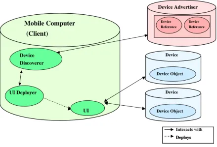
Figure 7 shows a general architecture that abstracts existing infrastructures for deploying single device user-interfaces. The architecture consists of several components: mobile computers, devices, device objects, device advertisers, device references, device discoverers, user-interface deployers, composers, and user-interfaces. Device objects encapsulate the functionality of actual physical devices. They contain methods for invoking commands on devices and viewing device state. Device advertisers publish information about devices and references to them within a given network or physical space. They are accessed by device discoverers on mobile computers. Device advertisers
Mobile Computer (Client)
Interacts with Deploys Deploys Device
Discoverer
UI Deployer
UI
Device Device Object
Device
Device Object Device Advertiser
Device Reference
17
may run on the same host as that of the device objects or on a separate machine. User-interface deployers on mobile computers, using device references, deploy the actual user-interfaces for interacting with device objects.
Given this general architecture, in the single-device case, we are concerned with the following question: how does a interface deployer produce an appropriate user-interface that can interact with the object of a user’s target device? We separate current forms (Figure 8) of interface deployment into two high-level approaches: user-interface generation and the predefined approach. The predefined approach places pre-existing user-interface code at well-known servers for user-interface deployers to find and execute. Since these servers behave as factories [11] supplying user-interface code, they are called user-interface factories. Based on whether the location of the factory is the client or some other location, an approach is respectively classified as client-factory or remote-factory. A previous scenario from Section 1.2 illustrates the client-factory approach, in which the vacationer pre-installs the security system’s user-interface on a mobile computer before leaving home. A remote-factory may be on a device or some third-party server. Under the device factory approach, the vacationer would download the user-interface code directly from the security system. Using the third-party factory approach, the vacationer could download code from a server at home or from the security system manufacturer’s website.
Figure 8. Current UI deployment approaches
UI Deployment
UI Generatio n Predefined (UI)
Client Client
Factory Remote
Factory
Device Factory
3rdParty
18
Recall that the converse of the predefined approach is the user-interface generation approach because it does not require devices to be loaded with pre-defined user-interface code. Again, a user-interface generator dynamically creates an appropriate user-interface by using information extracted from a device’s functional description. The generator can reside on the client device or on remote machine.
To show how all approaches could work, we will now summarize several commercial and research infrastructures that demonstrate them: Palm/Pocket-PC IR Control Programs, Jini, Moca, CoolTown, UPnP, ObjectEditor, Hodes’ System, Personal Universal Controller, and ICrafter.
2.1.1 Palm/Pocket-PC IR Control Programs
Figure 9. The IR port on the front end of the Ipaq for transferring data and controlling
IR devices.
Many of today’s palmtop computers offer IR ports (Figure 9) that are typically used to transmit data between one another. Programs, such as OmniRemote[2] and Nevo[1] , have been written for using these IR-ports to also control devices. In general, these programs provide users with user-interface building ‘wizards’ for creating and arranging buttons of a given device. During this process, users must also teach the system what IR-signals to emit for each button. Users can achieve this task in a manner that is similar to traditional remote controls. That is, they can enter predefined codes that are associated with specific devices. To allow users to create user-interfaces for devices that have no predefined codes, these programs also offer an IR recording feature. With this feature, users can push the buttons on the traditional remote controls of their unknown devices and record the signals emitted. They must then match the recorded signals to the corresponding buttons on the user-interfaces they created. After creating user-interfaces
19
(Figure 10), users can then save them on their palmtops for future use. Thus, Palm/Pocket-PC IR control programs support the client-factory approach.
A problem with IR control programs is that they require users to be in the vicinity of the devices they wish to control. Recall from earlier that this limitation is inherent of any IR-based method of device interaction. The infrastructures we discuss below avoid this limitation by supporting device interaction over the Internet.
Figure 10. A TV user-interface created using OmniRemote[2]
2.1.2 Jini (Service UI Approach)
Sun Microsystems created Jini[36] as a general infrastructure for building Java-based distributed systems. This infrastructure can also be used to network actual devices. It provides a framework that allows: (a) devices to join a network, (b) clients to discover devices, (c) and clients to access references (stubs) of remote devices to directly interact with a device (e.g. make remote procedure calls).
20
A limitation of the Service UI framework is that it is based on Java. As a result, clients that cannot run a JVM are unable to interact with Jini-based devices.
2.1.3 MOCA
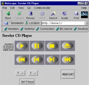
Similar to Jini, IBM’s MOCA[4] is a Java-based infrastructure for building distributed systems, possibly containing networked devices. However, MOCA separates its user-interface deployment from its Java dependency. Devices can execute Java servlets that provide HTML-based user-interfaces to their clients (Figure 11). Thus, MOCA supports the device factory approach. Clients that support the HTML web standard can interact with a MOCA device.
Figure 11. A CD player HTML-based user-interface inside a Netscape Browser.
2.1.4 Cooltown
HP’s Cooltown[19] is another infrastructure that supports a web-based device factory approach. However, unlike MOCA, it does not require devices to be implemented using a specific language. It simply expects devices to execute webservers that provide HTML-based webpages that present user-interfaces.
2.1.5 Universal Plug and Play (UPnP)
21
download. The two infrastructures, however, significantly differ in how they address other areas such as discovery and security. To illustrate, UPnP supports the AutoIP protocol[38], which allows devices to dynamically join a network by assigning themselves an IP address. Cooltown devices, on the other hand, require an administrator to manually register them to a network. Further, Cooltown offers specific mechanisms to address security while UPnP currently does not.
2.1.6 ObjectEditor
ObjectEditor, developed here at UNC, is an example of the client-side generation approach. It is fairly complex system and has been used in the computer science department to generate user-interfaces for various research projects and also teaching. Here, we describe those aspects of it that specifically apply to generating device user-interfaces.
ObjectEditor can generate a GUI displaying the state properties and operations of a device coded as a Java object. It assumes that these components are described using programming patterns. In particular, state properties are described by signatures adhering to the Java Beans conventions mentioned earlier in Section 1.3. ObjectEditor supports additional kinds of conventions for describing state properties. However, these conventions are beyond our scope of device user-interface generation. Signatures that are not used to export state properties describe operations. To illustrate, the method signature ‘public void power()’ describes the ‘power’ operation for turning the TV on and off.
22
To control a device, a user can select the menu items and push buttons on the user-interface or edit the values displayed by property widgets. Activating a button or menu item results in ObjectEditor invoking the associated method. If the method has parameters, the generator creates a dialog box consisting of widgets for entering desired parameter values. Suppose that a TV offers a sleep(int) method that accepts the number of minutes to wait before it automatically shuts off. If a user pushes the method’s button, ObjectEditor would generate a dialog box providing a textbox for entering the sleep time.
When a user edits the value in a property widget, the generator invokes the setter method of the associated property, passing the new value as a parameter. For example, when a user types in a new TV channel in the channel property’s textbox, ObjectEditor would invoke setChannel() with the new channel as a parameter. Figure 12 illustrates this entire process.
Figure 12. A depiction of how ObjectEditor works.
2.1.7 Hodes’ System
ObjectEditor is language-dependent because it requires devices to be coded in their native language, Java. This limits the kinds of devices for which it can generate user-interfaces.
TV Interface (Java)
public interface Te lev ision {
public void power(); public void mute (); public void v ol_Up(); public void v ol_Down(); public void ch_Up(); public void ch_Down();
public int ge tBrightne ss(); public void se tBrightne ss(int b); public int ge tChanne l(); public void se tChanne l(int c); …
ObjectEditor
generates
Property views initialized with ‘getter’ result Property values updated with ‘setter’ calls
command buttons
property views
Property views initialized with ‘getter’ result Property values updated with ‘setter’ calls
command buttons
property views
command buttons
property views
operations
state properties (Java beans)
Java Reflection
operations
state properties (Java beans)
23
Hodes’ System, a client-side generator, overcomes this limitation by offering a language-neutral generator. It generates user-interfaces from XML-based functional descriptions of devices (called services), such as the lamp description below:
<service name='lamp'> <label>lamp</label>
<addrspec>sn140.cs.unc.edu/0001</addrspec> <method name='power'>
<param lextype="enum:on,off,dim"> state </param> </method>
</service>
These descriptions consist of several tags for specifying values for the name, methods, method parameter types, and address of a service. Hodes’ System generates a GUI that consists of a button for each method and an appropriate set of widgets for entering parameter values. The description above would be used to generate a user-interface that resembles the one shown in Figure 13. In the user-interface, the ‘power’ method parameter, called ‘state’, maps to an option box containing choices for each possible value. Once a user pushes a method’s button, the generator performs a remote procedure call—sending the method’s name and parameter values to the service’s network address specified by the <addrspec> tags.
Figure 13. A lamp UI generated by Hodes’ System [15, 16].
Although Hodes’ System offers the flexibility of a language-neutral approach, it requires programmers to take the time to write descriptions in a separate language from the one in which their devices are coded.
2.1.8 Personal Universal Controller (PUC)
24
programmer to embed a rule that a generator should keep the cassette navigation buttons of a stereo together and in a particular order (Figure 14). The generator would adhere to such rules when generating user-interfaces. Since these customization rules (or declarations) must be manually written, the PUC system supports semi-automatic generation.
Figure 14. A portion of a stereo system user-interface generated by PUC [27]. Notice
the cassette navigation buttons are specifically grouped together.
2.1.9 ICrafter
25
interfaces, ICrafter be used to also compose multiple devices. In the next section, we will describe how this is possible.
Figure 15. (left) the HTML generated for setting a projector input; (right) the rendered
web page[28].
2.2 Deploying Multi-Device User-Interfaces
We extend the earlier general architecture to describe user-interface deployment in the multi-device case (Figure 16). In this case, the architecture includes composers, which use references from multiple devices to appropriately support some given set of composition semantics. These composers use user-interface deployers to deploy multi-device user-interfaces for the multi-devices they compose. There are two current ways to organize composers within an infrastructure.
26
Figure 16. Two possible ways to organize composers.
In the other approach (Figure 16b), there is no notion of virtual devices. Instead, aggregation and user-interface deployment are tightly integrated. Meaning, a composer directly interacts with a user-interface deployer that is: (1) aware of the composer’s supported semantics and (2) capable of deploying user-interfaces for achieving those semantics. To support the lights scenario under this approach, a composer and user-interface deployer would cohesively work together to deploy the user-user-interface for turning off all the lights.
To show how these two high-level approaches can actually work, we will describe how specific infrastructures apply them. This discussion will fully illustrate the tradeoff between high-level support and composition flexibility mentioned in the previous chapter, thus motivating our High-Level and Flexible Composition Hypothesis.
2.2.1 Cougar and TinyDB
Cougar[5] and TinyDB[22] are two systems that were built to support queries for data over sensor networks. An example Cougar query is: get the ‘current rainfall’ value of
each sensor in Tompkin County. Both Cougar and TinyDB implement mechanisms for
performing such queries automatically and efficiently. They both work by requiring that devices advertise their attributes in distributed database relations and provide a relational
UI Deployer UI UI Deployer UI Virtual Device Virtual DeviceVirtual Device Virtual DeviceVirtual Device Virtual Device Composer Reference Composer Composer Reference UI Deployer UI References References References UI Deployer UI UI Deployer UI UI (a) (b) Composer Composer References
Like a single
device UI Deployer
UI UI Deployer UI Virtual Device Virtual DeviceVirtual Device Virtual DeviceVirtual Device Virtual DeviceVirtual Device Virtual Device Composer Composer Reference Reference Composer Composer Reference UI Deployer UI UI Deployer UI UI References References References References UI Deployer UI UI UI Deployer UI UI (a) (b) Composer Composer References
27
language to query these attributes. Device programmers, however, must write code that transfers state from device objects to database relations. This database-oriented framework of Cougar and Tiny follows the non-integrative composition approach described above. In essence, the two systems compose a group of distributed devices into single database—thus allowing a single user-interface program to be written for accepting arbitrary queries and returning results.
Both systems have limited flexibility in the composition semantics that they can support. They only compose devices using queries and do not provide frameworks for supporting other semantics described later.
2.2.2 Hodes’ System
Hodes’ System allows a user to interact with a set of devices through a single compound user-interface rather than their individual user-interfaces. For example, it can allow all the lamps in a conference room to share a single user-interface containing the commands for controlling them. Like Cougar and TinyDB, it also follows the non-integrative composition approach. To deploy compound user-interfaces, it generates user-interfaces from manually generated XML-based descriptions of compound (virtual) devices that encapsulate descriptions of multiple devices. The ‘conference room lights’ virtual device could be described as the following:
<service name = ‘Conference Room Lights’>
<label>Conference Room</label>
<addrspec>sn011.unc.edu/0001</addrspec>
<service name = ‘lamp1’>
<label>Lamp 1</label>
<addrspec>sn011.unc.edu/0001</addrspec> <method name = ‘on’></method>
<method name = ‘off’></method> <method name = ‘dim’></method> <method name = ‘brighten’></method>
</service>
<service name = ‘lamp2’>
<label>Lamp 2</label>
<addrspec>sn011.unc.edu/0002</addrspec> <method name = ‘on’></method>
<method name = ‘off’></method> <method name = ‘dim’></method> <method name = ‘brighten’></method>
28
A generated user-interface for the ‘conference room lights’ device would resemble the one shown in Figure 17, which vertically places the individual user-interface of each lamp on top of one another.
Hodes’ System supports a limited set of composition semantics. It does not support device queries as Cougar and TinyDB do. Further, it does not support other semantics demonstrated by the other systems below.
Figure 17. A compound UI for a set of lights.
2.2.3 Palm/Pocket-PC IR Programs
Beyond the ability to create single device user-interfaces, these programs allow a person to build compound user-interfaces as supported by Hodes’ system. They provide wizards for users to merge the single device user-interfaces they design (as described in 2.1.1) to form compound user-interfaces. In addition, they typically allow users to create macro buttons that automatically invoke specific sequences of commands from multiple devices. For example, they could allow a person to create a ‘watch DVD button’. When pushed, the button invokes six different operations that prepare a TV, DVD, and receiver for watching a movie:
1) Turn on the TV
2) Set TV to DVD video input channel 3) Turn on the receiver
4) Set the receiver to DVD audio input 5) Turn on the DVD player
29 2.2.4 WebSplitter
WebSplitter[13] can compose devices together to present different types of content contained in a set of web pages. For instance, it can compose an audio system, projector, and other display devices to present a multimedia web presentation consisting of visual frames (images and text) and audio content. The display devices show the content slides, navigation buttons, and notes of the presentation while the audio player plays the audio (Figure 18).
Figure 18. A Websplitter presentation in which audio is sent to a stereo and frames are
shown in display devices [13].
As a speaker navigates through this web presentation, WebSplitter automatically delivers the URLs of content in each page to the appropriate devices.
In order to properly map or ‘split’ the content of a web page to their associated devices, it requires users to write XML-based policy files. These files specify mappings between the content of each page and the kinds of devices that should receive them. The policy file for our example presentation could contain syntax such as the following:
<cmdb:device name = “projector”>
<cmdb:taglist>
presentation, head, title, nav_bar, slides, picture </cmdb:taglist>
</cmdb:device>
30 <cmdb:device name = “sound system”>
<cmdb:taglist> audio </cmdb:taglist>
</cmdb:device>
<cmdb:device name = “cellphone”>
<cmdb:taglist> nav_bar, </cmdb:taglist>
</cmdb:device>
It specifies that: (1) the projector should receive all content except the speaker’s private presentation notes, (2) the audio system should receive all presentation audio, and (3) the speaker’s cell phone should receive the navigation bar for controlling the presentation’s pace. For each page in the presentation that the speaker visits, WebSplitter refers to the defined mappings in the policy file to correctly direct the page’s content. WebSplitter’s set of supported composition semantics is limited. It cannot achieve any of the semantics facilitated by the other systems described above and some below.
2.2.5 ICrafter
ICrafter provides a general framework for actually writing multiple composers supporting different composition semantics. It is unlike the systems described above which offer preprogrammed composers that support a fixed and limited set of semantics. To provide a general framework for composition, ICrafter’s composers work in terms of the programming interfaces of devices rather than their classes. Since programming interfaces are more general than classes, this approach provides a way for single composers to compose families of heterogeneous devices.
Figure 19. A lights composition.
To illustrate, consider a system with lights shown in Figure 19. Suppose that the two lights implement a PowerSwitch interface that declares a power() method for turning the lights on and off. A programmer can write a PowerSwitchAll composer for this
Powe
rSwitc
h
Powe
rSwitc
h
Powe
rSwitc
h
Powe
rSwitc
h
Powe
rSwitc
h
Powe
rSwitc
31
programming interface that provides the ability to simultaneously turn these lights on and off. This composer provides the system with a regular expression describing that it composes devices implementing the PowerSwitch interface (Table 1). In turn, the system matches the composer with the two lamps and presents the match to a user. A user’s selection of this match results in the PowerSwitchAll composer generating a user-interface consisting of a ‘power all lights’ button. When the button is pushed, the composer invokes the well-known power() method of each lamp. This example shows that ICrafter follows the integrative composition approach mentioned earlier. Composers offer their own generators for dynamically creating user-interfaces that are specific to their supported semantics and users’ target devices.
Regular Expression Composer
{PowerSwitch*} PowerSwitchAll
Table 1. An example composer registry.
Figure 20 depicts a different composition scenario, which involves transferring images in a camera to a display device for viewing. Let us assume that the camera and display device implement a DataProducer and DataConsumer interface respectively. The
DataProducer interface declares a produce() operation, which returns a value to
transfer, and the DataConsumer interface declares a consume() operation, which accepts the value. A programmer can now write a DataPipe composer that allows the camera and display device to exchange data. This composer provides the system with a regular expression describing that it composes devices implementing the DataProducer and
DataConsumerinterfaces (Table 1).
Figure 20. An example composer registry.
Regular Expression Composer
{DataProducer, DataConsumer} DataPipe
Table 2. An example composer registry.
D
a
ta
P
roduce
r
Da
ta
C
o
ns
u
m
e
r
D
a
ta
P
roduce
r
Da
ta
C
o
ns
u
m
e
32
The system would match the camera and display device programming interfaces with
the DataPipecomposer and present the match to a user. A user’s selection of this match
results in the DataPipe composer generating a user-interface for invoking the transfer operation. Once the user invokes the operation on the user-interface, the composer calls the well-known methods of its associated programming interfaces to achieve the image transfer. That is, it makes a call that passes the value returned from camera.produce()
as an argument to display.consume().
An issue with performing data transfers is how DataProducer and DataConsumer
interfaces declare the data they exchange. Two options are to declare data as: (a) a generic object or (b) a programmer-defined type. In Java, the class Object demonstrates this notion of a generic data type. All classes in Java are subclasses of Object and can therefore be typecasted to it. Using generic objects, the two programming interfaces would be:
public interface DataProducer { public Object produce(); }
public interface DataConsumer {
public void consume(Object x); }
Here, the producer returns a value of type Object and the consumer accepts a value of that same type. An example of using programmer-defined types is below, in which the consumer and producer specifically exchange a Picture object:
public interface PictureProducer { public Picture produce(); }
public interface PictureConsumer { public void consume(Picture x); }
These two options raise a subtle tradeoff a programmer must make between type flexibility and programming cost.
33
they all produce and consume the same generic type. When interacting with many devices, this approach could result in lists of many false-positives—that is, matches between devices that cannot exchange data. An example of a false positive is a match between a camera that only produces picture objects and an alarm clock that consumes time objects. Another drawback of using generic objects is that a device can only consume or produce one kind of data because forcing the generic type does not allow overloading of the consume() and produce() methods in the programming interface declarations. Therefore, the camera could not independently produce URLs to both pictures and recorded video.
Supporting programmer-defined types in programming interfaces reduces the production of false positives because it allows consumers and produces to be matched by the types they exchange. It also allows overloading of the consume()and produce()
methods so that devices can exchange more than one data type. However, it incurs the costs of writing many composers that are specific to the data types that devices can exchange. To illustrate, it requires writing separate PicturePipe and VideoPipe
composers so that the camera can transfer two different kinds of data types.
The PowerSwitchAll composer raises another tradeoff the programmer must make in writing composable programming interfaces. Which programming interfaces should a device implement? Two extreme options are a programming interface for all operations of a device or a programming interface for each operation. The first piece of code below is an example of the former approach while the second demonstrates the latter:
1) public interface Light {
public void power(); public void dim();
public void brighten(); }
2) public interface PowerSwitch {
public void power(); }
public interface DimSwitch { public void dim(); }