UML Modeling of Network
Topologies for Distributed
Computer System
Vipin Saxena and Deepak Arora
Department of Computer Science, Babasaheb Bhimrao Ambedkar University (A Central University), Lucknow, India
Nowadays, distributed computer systems have become very popular approach of computing as it delivers high end performance at a low cost. In a distributed computing environment, autonomous computers are connected by means of a communication network, arranged in a geo-metrical shape called network topology. In the present paper a detailed study of network topologies is done for the distributed computer systems. A most popular Unified Modeling Language(UML)is used for modeling the different network topologies. A comparative study is done for 2D Mesh, Torus, and Hypercube network topologies and their performance is also evaluated af-ter designing the UML Class, Sequence, and Activity diagrams for the same.
Keywords: network topology, class diagram, sequence diagram, activity diagram
1. Introduction
Distributed computing systems have become the essential aspect of growing information tech-nology. The performance of any distributed sys-tem is certainly influenced by the technology, which we adopt in making network intercon-nections. Various researchers have done a lot of work on UML modeling, but limited research papers are available on UML modeling related to the distributed computer systems.
UML developed by Booch et al. [1]has proved itself as the most suitable visual presentation platform for modeling the real world problems. Conallen[2]has defined the extensions in UML for modeling the designing issues related to any web application architecture. Coulouris, G. et al. [3], has explored the major challenges re-garding distributed systems through
architec-tural and fundamental models; various tech-nologies and case studies on Ethernet, wireless LAN and ATM are also discussed. Huang and Bode[4]compared the performance of ring and tree based network topologies for the distributed systems and also suggested a distributed man-agement system for handling the failure. Issues related to the implementation of distributed sys-tems are well explained by Milenkovic, M.[5]. OMG [6, 7] elaborate the latest UML specifi-cations related to all real world problems, their modeling aspects and also the way of presen-tation for XML metadata specification in UML diagrams along with standard storage represen-tations. Pllana and Fahringer [8] have sug-gested the way how one can do the UML mod-eling for high performance applications, which is an important reference in this regard. Fur-ther one more important reference by Pllana and Fahringer[9], describes the UML modeling of design issues related to the parallel and dis-tributed applications. Another object-oriented distributed architecture system is recently de-fined by Saxena V. et al. [10] through UML modeling, with a case study of a multiplex sys-tem.
sive to access any remote resources in terms of CPU overhead and communication cost. Nowa-days, a trend to develop distributed system is increasingly moving ahead due to its features like high performance computing, scalability, security and reliability.
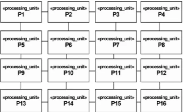
Figure 1.Distributed computer system.
Nowadays computation labs are adopting the concept of distributed computer systems, which is shown below in Figure 1. This figure shows the connection of ‘N’ autonomous clients to dif-ferent servers connected through a communica-tion network. This network can be based upon any kind of network topology as required, in terms of complexity, reliability and security.
2.2. Process Definition
Let us explain the definition of a process, which is the basic entity of execution in any distributed computing environment. The process is ex-plained as a macro, subprogram, subroutine or block of code etc., which has an identification number called as process id. A processing unit is defined as a Process Execution Controller
(PEC), which accepts process id through thread-ing and executes the correspondthread-ing process after
gion is defined as a buffer, which is handled by the multiple threads, associated to the different processes. A stereotype parallel region UML class diagram is shown in Figure 2(d)and asso-ciated activities representation is given in Figure 2(e). In this figure the sub activities can be ex-ecuted many times in concurrent fashion by the use of buffer, called code region.
Figure 2a.UML class diagram of process.
Figure 2b.Instance of process.
Figure 2d.UML class diagram of stereotype parallel region.
Figure 2e.Sample activity diagram.
2.3. Topology
The processes which are going to be executed, handled by the multiple threads, can use the par-allel region in a concurrent manner. For the ex-ecution and communication purpose, these pro-cesses need to be arranged in a network topol-ogy. By the use of topology, the process can access the code region as per the availability of the resources, for faster execution.
In the present approach, different kinds of topolo-gies are selected, which are widely used in setting the labs for distributed computations. Through these topologies, which are executed in concurrent fashion, one can save a lot of pro-cess execution time. The UML class diagrams for these three kinds of topologies are given in Figure 3(a), 3(b), and 3(c)for 2D Mesh, Torus, and Hypercube topology respectively. For the execution of process having unique process id, the resources can be granted by the individual computer system or can be taken from differ-ent clidiffer-ents as per the availability of the network, which consists of autonomous computer sys-tems arranged in the distributed computing en-vironment.
Figure 3a.UML class diagram of 2d mesh topology.
Figure 3b.UML class diagram of torus topology.
Figure 3c.UML class diagram of hypercube topology.
2.4. Communication Lines
Figure 4a. UML class diagram of broadcast signal.
Figure 4b.UML class diagram of P2P signal.
Figure 4c.Signal event for process communication via broadcast approach.
Figure 4d.Signal event for process communication via P2P approach.
3. UML Class Diagram for Distributed Computer System
In a distributed computing environment, mes-sages get communicated to and from the nodes in the form of signals for the process synchro-nization.
In Figure 5, one can see that class Process Exe-cution Controller (PEC) is directly interacting with the class Process, Communication Line, Processor, Memory and D Cache(Data Cache), I Cache (Instruction Cache). Class Process is responsible for all the process-related tasks like process creation, deletion and synchronization etc.
Here, class I Cache is responsible for caching the instructions whereas D Cache is respon-sible for caching the data. The PEC would
Figure 5.UML class diagrams of distributed computer system.
store/search the needed instruction or data dur-ing the process execution with the help of Pro-cessor and Memory. Here, PEC is fully respon-sible for any processes. Now, if one considers the communication lines, they must arrange in some topology, through which a message can refer to any process in the distributed environ-ment. Also the process referred by message can exist on any of the nodes in the distributed environment.
So, the network topology adopted for the com-munication lines becomes a key point for mea-suring the performance of any distributed com-puter system. The authors have chosen three topologies, 2D Mesh Torus, and Hypercube for their purpose. The Broadcast and P2P are the classes which handle the broadcasting and point-to-point relay of communication signals over communication lines.
4. UML Activity Diagram for Distributed Computer System
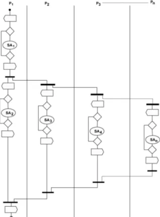
Processes, which are going to be executed in a parallel fashion, must share a common par-allel region. In Figure 6, it is shown that any subactivity belonging to any process can share the parallel region for executing in par-allel along with other subactivities from SA1,
SA2. . .. . .SAn, which can belong to any pro-cess from P1, P2. . ...Pn. This will facilitate the process to share a common parallel region, to be executed with multiple instruction stream too. In Figure 6, one can see that it can be shown by using fork operation. When fork operation is applied on subactivity, it breaks apart into two different subactivities and starts executing parallely by sharing a common parallel region. After completing the most nested parallel sub-activity, the joint operation can be performed. Through joining the result from each parallel subactivity, one can reach the final result of the parent subactivity. In this case, the subactivities executing in parallel can be applied on multiple data stream too.
Figure 6.UML activity diagram for process under distributed environment.
5. UML Sequence Diagram for Process Execution in Distributed Computer System
Communication channel carries the messages in the form of signals among the process being executed concurrently in the distributed com-puting environment. In Figure 7 it is shown how the messages are passed among various classes like Process, Communication Lines, Pro-cess Execution Controller, D Cache, I Cache, Processor and Memory, involved in process execution under distributed computer system. After receiving message from Communica-tion Line, the process stream, handeled by Pro-cess class, is submitted to the PEC for execution. When PEC receives complete process stream, it will start to cache the needed instructions and data separately into I Cache and D Cache re-spectively. Now PEC sends the message to the Processor to start decoding and after de-coding the required operands and instructions are loaded into the memory taken from I Cache and D Cache with the help of PEC. Now PEC sends the message to the Processor and Pro-cessor starts the process execution. During the execution, Processor uses the Memory for sav-ing intermediate results, data and instructions. After completing the execution, the final result would be saved in the Memory and Processor sends an execution completed message back to the PEC. Now PEC will also send back the ex-ecuted process information to the Process.
6. Comparison of Space Complexities among Topologies
Topology One to One One to All All to All
2D Mesh 2(√n−1) 2(√n−1) 2x(√n/2)
Torus √n/2 √n/2 2x√n/2
Hypercube Log2n Log2n 2 x Log2n
Table I.Space complexities for 2D mesh, torus and hypercube.
Hy-Figure 7.UML sequence diagram for process execution under distributed computer environment.
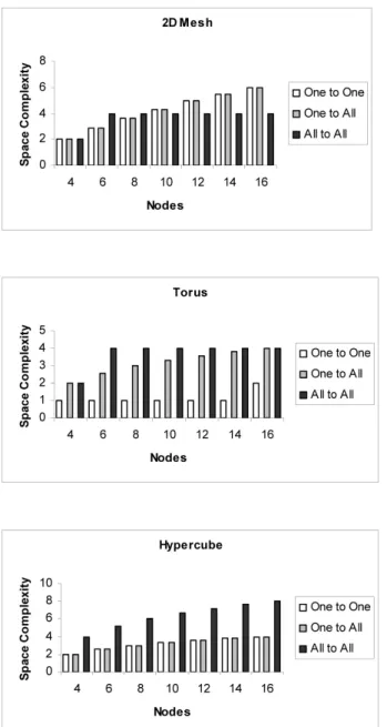
percube technologies. The communication is considered as one to one, one to all and all to all. Table I gives the measurements of space complexities for 2DMesh, Torus and Hypercube technologies. On the basis of this table, Table II, III and IV are designed, which shows the comparison of space complexities as number of nodes in the network system under distributed environment is increasing. As nodes are in-creasing, the performance of Torus topology comes best over the 2D Mesh and Hypercube network technologies since the space complex-ity is low in case of Torus topology for one to one communication. In case of one to all com-munication system, behaviour of Torus and Hy-percube is the same whereas, in case of one to all, performance of 2D Mesh and Torus topolo-gies is the same. This is also depicted in Figure 8, in which it is studied that, in general, perfor-mance of Torus topology is better in comparison with 2D Mesh and Hypercube technologies.
No. of 2D Mesh
(MXN) Nodes One to One One to All All to All
2x2 4 2 2 2
2x3 6 3 3 4
2x4 8 4 4 4
2x5 10 4 4 4
2x6 12 5 5 4
2x7 14 5 5 4
2x8 16 6 6 4
Table II.Space complexities for 2D Mesh topology.
No. of Torus
(MXN) Nodes One to One One to All All to All
2x2 4 1 2 2
2x3 6 1 3 4
2x4 8 1 3 4
2x5 10 1 3 4
2x6 12 1 4 4
2x7 14 1 4 4
2x8 16 2 4 4
No. of Hypercube
(MXN) Nodes One to One One to All All to All
2x2 4 2 2 4
2x3 6 3 3 5
2x4 8 3 3 6
2x5 10 3 3 7
2x6 12 4 4 7
2x7 14 4 4 8
2x8 16 4 4 8
Table IV.Space complexities for Hypercube topology.
Figure 8.Comparison of space complexities.
7. Conclusion and Future Scope of Work
From the above work, it is concluded that UML is one of the important modeling languages used for the visual representation of research problem/software design. In this paper, per-formance of three kinds of topologies i.e. 2D Mesh, Torus and Hypercube is considered un-der the distributed environment and it is con-cluded that the Torus topology is the best kind of arrangement of computer system under dis-tributed environment since the space complexity is less as the nodes are increasing in comparison with other topologies. Since the present work is only confined to the static interconnection of the network topologies, this research work can also be extended further, by considering the dynamic arrangement of interconnection of computer network.
References
[1] BOOCH, G., RUMBAUGH, J., JACOBSON, I., The Uni-fied Modeling Language User Guide, Addison Wes-ley, Reading, MA, 1999.
[2] CONALLEN, J., Modeling Web Application Archi-tectures with UML.Communications of the ACM 42(10),(1999), pp. 63–70.
[3] COULOURIS, G., DOLLIMORE, J., KINDBERG, T., Dis-tributed Systems, Concepts and Design, Third Edi-tion, Addison Wesley, 2000.
[4] HUANG, M., BODE, B., A Performance Comparison of Tree and Ring Topologies in Distributed System.
Proceedings of the IEEE, Parallel and Distributed Processing Symposium,(2005), Washington, D.C.
[5] MILENKOVIC, M., Operating Systems: Concepts and Design, Tata Mcgraw-Hill, 1997.
[6] OMG, Unified Modeling Language Specifica-tion. Available online via http://www.omg.org (2001).
[7] OMG, OMG XML Metadata Interchange
(XMI) Specification. Available online via
http://www.omg.org(2002).
[8] PLLANA, S., FAHRINGERT., On Customizing the UML for Modeling Performance-oriented Applica-tions.Proceedings of the<<UML>>2002,”Model Engineering Concepts and Tools”, Springer-Verlag,
(2002), Dresden, Germany.
B.B. Ambedkar University(A Central University)
Vidya Vihar Rae Bareilly Road Lucknow U.P. 226025, India e-mail:[email protected]
Deepak Arora Department of Computer Science B.B. Ambedkar University(A Central University)
Vidya Vihar Rae Bareilly Road Lucknow U.P. 226025, India e-mail:[email protected]
VIPINSAXENAis a Reader, Dept. of Computer Science, Babasaheb Bhimrao Ambedkar University, Lucknow, India. He got his M.Phil. Degree in computer application in 1991 & Ph.D. Degree in scientific computing from the University of Roorkee(renamed as Indian Institute of Technology, India)in 1997. He has more than 12 years teaching experience and 16 years research experience in the field of scientific computing & software engineering. Currently he is proposing software designs by the use of Unified Modeling Language for various research problems related to the software domains & advanced computer ar-chitecture. He has published more than 55 international and national publications.