LUCIFER
LMS User Manual
LMS Version 1.60
Document Number: LBT-LUCIFER-MAN 030 Issue Number: Issue 1.0
Issue Date: July 8, 2010
Contents
1 Introduction 1
1.1 Scope . . . 1
1.2 Changes . . . 1
1.3 Abbreviations . . . 2
1.4 Reference Documents . . . 2
1.5 Acknowledgments . . . 2
2 Overview and Requirements 3 2.1 The LMS Concept . . . 3
2.2 Some technical details . . . 3
2.2.1 Linux Installation . . . 3
2.2.2 Other Operating Systems . . . 3
2.2.3 Directories and Paths . . . 3
2.2.4 Start-up of LMS . . . 4
2.2.5 Input and output files . . . 4
2.3 LMS Modes . . . 5
2.4 Input frames and catalogs . . . 5
2.4.1 Astrometric Requirements . . . 5
2.4.2 Pre-Images with LUCIFER . . . 5
2.4.3 Requirements for Contributed Input Images . . . 6
2.4.4 Input Catalogs and Frame-less Modes . . . 6
3 Mask Preparation 8 3.1 Overview . . . 8
3.1.1 Loading a FITS File or a Catalog . . . 8
3.1.2 Initializing and Positioning the Mask . . . 8
3.1.3 Configuring the instrument . . . 9
3.1.4 Reference Star Selection . . . 10
3.1.5 Guide Star Selection . . . 11
3.1.6 Slit Positioning . . . 11
3.2 Basic Movements and Functionalities . . . 13
3.3 Reference Stars and Target Acquisition . . . 13
3.4 Finding Guide Stars for the LBT . . . 14
LUCIFER LMS User Manual Issue 1.60 LBT-LUCIFER-MAN 030 ii
3.5 Instrument settings . . . 14
3.6 Creating Slits . . . 15
3.7 Saving Masks . . . 16
4 Local Catalogs 18 4.1 Catalog Format . . . 18
4.2 Creating a Local Catalog from a Web Search . . . 19
4.3 Building Your Own Catalog . . . 19
4.4 Local Catalogs and Auto-Slit . . . 21
5 LMS Menu Reference 22 5.1 Init Mask . . . 22
5.2 Reset Mode . . . 22
5.3 Load SetUp . . . 22
5.4 Quit Mode . . . 23
5.5 Auto-Slit . . . 23
5.6 Save . . . 23
5.7 Reference Targets . . . 24
5.8 Guide Stars . . . 24
5.9 Status Panel . . . 24
5.10 Config / Layout . . . 25
5.10.1 Instrument Configuration . . . 25
5.10.2 Graphical Layout Options . . . 26
5.10.3 Special Options . . . 26
6 Technical Masks 27
List of Figures
2.1 LMS . . . 4
3.1 Screen-shot Menus . . . 9
3.2 Screenshot Mask . . . 12
A.1 The LBT Guide Star Patrol Field . . . 28
List of Tables
6.1 List of LUCIFER technical masks . . . 27
Chapter 1.
Introduction
1.1
Scope
This manual explains the usage of the LUCIFER Mask Simulator (LMS). It should be used together with the LUCIFER user manual.
1.2
Changes
Attention: Masks prepared with LMS version 1.4 or lower cannot be used for observing after February 2010. lms files generated with version 1.4 or lower should not be loaded into LMS version 1.50 or higher.
The major changes of LMS 1.50 as compared to LMS 1.4 are:
1. The sign of the mask rotation angle has been changed to comply with the sign convention of the LBT instrument rotator. As a consequence, a new telescope pointing mode had to be introduced for MOS observations.
2. Measured values for the LUCIFER pixel scales are now used instead of the design values. 3. Only one gerber file is generated which can be read by the LBT cutting machine as well as by the
machine of the supplier in Munich.
4. Slit center positions can be modified in the slit menu (positions are given in mm focal plane relative to the mask center).
Changes made between LMS 1.50 and 1.51:
1. The variablelochosthas been removed to avoid problems with different operating systems. The only effect being that the name of the computer on which the mask was generated is no longer listed in the lms-file.
2. A red rectangle is drawn close to reference aperture 6. This rectangle indicates the area occupied by the mask ID number. No slit spectrum should interfere with this rectangle.
3. The correction for thermal contraction of the mask in LUCIFER (0.0025% shrinking during cool-down from ambient to -200 C) has been removed from the code. Instead, the thermal contraction is taken into account by adapting the telescope plate scale. Thus, the distinction between LUCIFER images and external images or catalogs is obsolete.
Changes made between LMS 1.51 and 1.52:
1. In the SkyCat window, the sign of the mask rotation angle listed together with the telescope pointing was wrong. This has been corrected, the rotation angle displayed is now consistent with the angle listed in the lms-file (TEL.ROT.OFFANGLE).
2. The equations determining the positions of the blue lines limiting the area of unclipped spectra in the field of view have been corrected.
Changes made between LMS 1.52 and 1.53:
1. The mask center position no longer changes when a mask that has been shifted relative to the image center is reloaded. The mask can now be shifted all over a large FITS image without restric-tions.
2. Using the Auto-Slit option with a rotated mask no longer changes the sign of the mask rotation angle.
LUCIFER LMS User Manual Issue 1.60 LBT-LUCIFER-MAN 030 2
3. A check for at least three reference star has been implemented. A warning appears when the mask is saved with less than three reference stars.
4. A description of how to generate a SkyCat compatible catalog has been added to the manual. Changes made between LMS 1.53 and 1.60:
1. TheAuto-Slitfunctionality has been implemented in Tcl/Tk. The C++ code (binaryAP) is obso-lete. This eliminates the problems with compiling the C++ code on operating systems other than LINUX.
2. The part of this manual dealing with local catalogs and source lists has been rewritten.
3. The display of the array back projection on the focal plane has been modified. Only the contour of the accessible array area is plotted. I.e., the full width of the array (over which the spectra can extend) is indicated, but the height is limited to the field height.
1.3
Abbreviations
FOV field of view
ISF instrument summary file LMS LUCIFER mask simulator
WCS World Coordinate System (Ra and Dec)
1.4
Reference Documents
The following documents are referenced in this document: [1] FORS1+2 FIMS Manual, VLT-MAN-ESO-13100-2308
[2] The ESO SkyCat Tool, Programmer’s Manual, VLT-MAN-ESO-19400-1552 [3] Real Time Display, User Manual, VLT-MAN-ESO-17240-0866
[4] Astronomical Catalog Library, User Manual, GEN-SPE-ESO-19400-0949 All these documents are available on the ESO web-pages.
1.5
Acknowledgments
Chapter 2.
Overview and Requirements
2.1
The LMS Concept
LMS, the LUCIFER Mask Simulator, is a LUCIFER observer support software. It is based on FIMS, ESO’sFORSInstrumentMaskSimulator. LMS is a plug-in to the ESO SkyCat tool, a browser for as-tronomical images and catalogs. SkyCat either displays a FITS image or source positions loaded from a catalog. LMS overlays the contour of the LUCIFER field of view (or the mask area) together with the contour of the accessible detector area back projected on the telescope focal plane. Within the LUCIFER field of view, MOS-slits can be positioned and reference stars can be selected. In addition, guide stars can be selected in the guider patrol field which partially overlaps with the LUCIFER field.
LMS is written in Tcl/Tk and has been tested under OpenSuse Linux 10.3 to 11.2 using SkyCat 2.7.3 and SkyCat 3.0. The SkyCat/LMS package can be installed and used at the user’s home institute.
2.2
Some technical details
2.2.1 Linux Installation
Besides the LMS-package, an itcl interpreter is required, which is part of standard Linux installations. The LMS-package can be downloaded from the MPE LUCIFER web page. The download file is named
lms vxxx.tar.gz, where xxxrepresents the version number. After unzipping the package, change to thelms vxxx/bin directory. This directory contains the start script lms.shand the SkyCat and AP (automatic positioning software) binaries. In caselms vxxxis located in the user’s home directory, execute the shell script to start LMS (type./lms.sh). Otherwise, open the script and modify the path
LMSROOTin line 49 to point to the LMS directory (see below), then run the script.
2.2.2 Other Operating Systems
LMS also runs under Mac OS. The corresponding SkyCat executable is not part of the LMS package and has to be downloaded from the ESO web pages.
2.2.3 Directories and Paths
We have kept the default FIMS directory structure for program and file locations. In case you want to organize your setup differently, just modify the paths in the lms.sh script. Starting in line 49 of the script, the directory structure is listed:
LMSROOT=${LMSROOT:-$HOME/lms_vxxx} ISF_DIR=$LMSROOT/lib/mos
INS_ROOT=$HOME INS_USER=.lms
PREP_DIR=$INS_ROOT/$INS_USER/PREP LOG_DIR=$INS_ROOT/$INS_USER/LOG SET_DIR=$INS_ROOT/$INS_USER/SET
The first line defines the path to the LMS directory, the forth line defines the name of the data directory. This list assumes that the program tree is /home/<user>/lms vxxx (with the lms.sh start script stored in thebinsub-directory, and the programs, libraries, and instrument files stored in thelib sub-directory), and that the data tree is/home<user>/.lms, containing fits files in thePREP, the log-files in theLOG, and the output files (.grb, .lms, .epsf) in theSETsub-directory.<user>refers to the user’s home directory. These paths can be modified by editing the corresponding lines with a simple text editor. Please make sure that the path to the lms directory is correct. The output directories are created by the start script in case they don’t exist.
LUCIFER LMS User Manual Issue 1.60 LBT-LUCIFER-MAN 030 4
2.2.4 Start-up of LMS
LMS is started from the$LMSROOT/bindirectory by calling the scriptlms.shwith or without a param-eter defining the instrument:
• ./lms.sh
• ./lms.sh l1
• ./lms.sh l2
where the first two commands start SkyCat with the LUCIFER1 menu, while the third one starts SkyCat with the LUCIFER2 menu (LUCIFER2 sub-menus are not yet implemented). Besidesl1andl2, the following arguments are also valid:L1,L2,Lucifer1/2, andLUCIFER1/2.
lms.shsets the paths to directories used by LMS, when run for the first time creates the hidden default directories (.lms/LOG, .lms/PREP, .lms/SET) in the user’s home directory, defines environment variables, configures the plug-ins for SkyCat, and starts SkyCat.
LMS is accessible via the LUCIFER menu in SkyCat. Mainly this menu is described here.
2.2.5 Input and output files
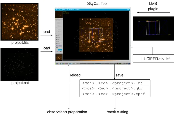
SkyCat handles FITS images and source catalogs, while LMS handles the LUCIFER instrument con-figuration, the positioning of the MOS slits, and the selection of reference and guide stars. The relation between the program modules and the input- and output-files is sketched in Fig. 2.1.
project.fits
load
-project.cat
load
-SkyCat Tool LMS
plugin
<mos> . <ec> . <project>.lms
<mos> . <ec> . <project>.gbr
<mos> . <ec> . <project>.epsf
6 reload
?
observation preparation
?save
? mask cutting
LUCIFER<i>.isf
Figure 2.1: Interaction between SkyCat and LMS - input and output files.
LUCIFER LMS User Manual Issue 1.60 LBT-LUCIFER-MAN 030 5
• A FITS image and / or a source catalog to be loaded into SkyCat (by default located in
.lms/PREPbut the path can be modified; images and catalogs can also be downloaded via the
Data-Serversmenu), and
• the instrument summary file (ISF, located inlms vxxx/lib/mos).
The ISF is an ASCII file containing all relevant instrument and telescope parameters, like camera and collimator focal lengths, grating parameters, filter central wavelengths and bandwidths, detector pixel size and pixel numbers, and telescope plate scale. Individual files exist for LUCIFER 1 and 2.
LMS produces three output files which are written to.lms/SET:
1. The*.lmsfile contains the instrument parameters and the telescope pointing set during the ses-sion, as well as the slit parameters and the positions of reference and guide stars. Reload this file to recover the LMS session.
2. The Gerber file (*.gbr) contains the information required for mask cutting. The mask configuration stored in the Gerber file can be displayed by a freeware viewer likegerbv.
3. The*.epsf file contains a postscript image of the mask for direct viewing in case a Gerber file viewer is not available (the mask ID is not shown in this image).
2.3
LMS Modes
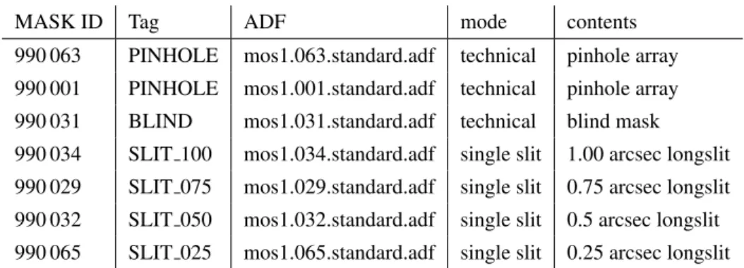
LMS supports two modes: MOS mode and technical mask mode. In MOS mode, new masks can be generated, and the three output files just mentioned are stored. In technical mask mode, an existing long-slit mask is loaded, and only the *.lms file is saved. For more details see chapter 3 on mask
preparation and chapter 6 on technical masks.
2.4
Input frames and catalogs
2.4.1 Astrometric Requirements
For preparing observations with LMS, a FITS file with appropriate world coordinate keywords (World Coordinate System WCS) in the header is required. Alternative inputs are catalogs in frame-less mode. Accurate target coordinates are required. The target positions relative to the coordinates of reference stars must be known very well, because the reference stars are used for mask alignment. A maximum astrometric error of 1/6 of the slit-width can be tolerated. Compromises in the astrometry will cause slit losses. For 0.5” wide slits, every single target coordinate must be known to better than 0.1” w.r.t the reference stars. This also implies that the telescope image scale and the pixel scale of the fits image (or the source positions in a catalog) have to be known to about 7·10−4.
2.4.2 Pre-Images with LUCIFER
Pre-images taken with both LUCIFER instruments can be used for mask preparation. However, the following aspects should be considered when processing images for mask preparation:
• Pre-images are take with the N/3.75 camera, resulting in a 4’ x 4’ field. In case the mask is shifted and/or rotated for slit positioning, part of the mask will be outside the image area. Moreover, the useful part of the auto guider patrol field is outside the image area in any case. The latter can be overcome by extracting stars from a catalog (because the relative position accuracy is not critical in this case), but it is normally desirable to have the full field for source and reference star selection. Therefore, a small mosaic centered on the science field should be recorded, the single images should be distortion corrected, merged into one FITS image, and provided as input for LMS. • LMS anticipates distortion corrected LUCIFER images. Distortions have been measured by
imag-ing a sieve mask on the detector. Images have to be distortion corrected before combinimag-ing them to a mosaic.
LUCIFER LMS User Manual Issue 1.60 LBT-LUCIFER-MAN 030 6
Remark 1:Presently (no adaptive optics available, seeing limited operation) 1 arcsec wide slits should be used to minimize slit losses by seeing. In case a single LUCIFER pre-image (no mosaic) is used, the mask is centered on the image, and the slits are positioned inside the white rectangle indicating low defocus (see Fig. 3.2), no distortion correction is required.
Remark 2:LUCIFER provides FITS images which are NOT compliant with the astronomy imaging stan-dard, but are flipped about the north-south axis, i.e. east is to the right of north. SkyCat and LMS handle this case correctly, therefore the mask image is also flipped as compared to standard images, and the slits are correctly positioned for both, LUCIFER and standard images.
2.4.3 Requirements for Contributed Input Images
Images from other telescopes require careful and accurate astrometric calibrations (and WCS FITS headers). If no FITS frame is available, it is possible to use the image server facilities of SkyCat to download a sky image from one of the available on-line archives. Note that also here the requirement for positional accuracy applies as stated in section 2.4.1.
The standard orientation for sky maps and images is north to the top, and east to the left, meaning RA is decreasing with increasing pixel number (image fits header keywords CDELT1<0 and CDELT2>0). If the input frame does not provide world coordinates, the FITS header can be edited by using either a FITS header editor oremacs. Verify this step very carefully. A faulty or inaccurate setting of the frame’s world coordinates will be carried over in all further steps. In particular the frame scales CDELT1, CDELT2 are very sensitive, while an offset between the WCS and the optical positions in the frame of less than 10 arcsec can be corrected by the alignment procedure.
To verify the correct setting of WCS keywords load your modified frame into SkyCat (select File Open... ) and watch the α and δ values in the panel, when moving with the mouse over the sky field. For further verification you can use the AstroCat facilities to download e.g. all appropriate tar-gets from catalogs like the Guide Star Catalog or the USNO catalog ( Data-Servers Catalogs
Guide Star Catalog at ESO Set from Image Search ) and compare the optical positions in the frame with the catalog positions.
The WCS FITS header keywords describe a linear map-projection scale, hence non-linear effects caused e.g. by the telescope or instrumental optics are not accounted for. The WCS FITS header key-words of LUCIFER1 and LUCIFER2 images contain the local scale in the center of the focal field (= center of the array = the optical axis).
LMS supports frames with a minimum size of 1’ x 1’. If the image size is close to the lower size limit, coordinate translations, in particular the positions of the mask elements outside the frame are no longer calculated via the built-in WCS package, but are extrapolated linearly from the WCS scale derived from the FITS frame header. The MOS slit positions are less accurate in this case.
2.4.4 Input Catalogs and Frame-less Modes
A frame-less mode is also offered. No FITS frame is required, but a WCS area is defined for the LUCIFER mask. This mode can be used if a target list with high astrometric quality is available. Reference stars have to be selected from stars with the coordinates known in the same astrometric coordinate system. To load a catalog from the web, proceed as follows:
• File Clear to clear the display and to purge the WCS
• Data-Servers Catalogs Guide Star Catalog or load another target catalog (with reliable as-trometry satisfying the requirements of section 2.4.1)
LUCIFER LMS User Manual Issue 1.60 LBT-LUCIFER-MAN 030 7
• adjust the image brightness by scrolling with B1 (left mouse button) the color bar below the main SkyCat window in case the virtual field or the source positions are not visible,
• press LUCIFER Init Mask and proceed further as in frame-mode
To save this catalog in the PREP directory, select the menu item File Save as . . . from the catalog query window. Choose a file name and the extensioncat. To reload the catalog, use Data-Servers
Chapter 3.
Mask Preparation
This section first gives an overview of the mask preparation and then describes the basic operations in some detail.
3.1
Overview
A typical LMS session should consists of the following steps: 1. change to thebinsub-directory in the LMS root directory 2. start SkyCat/LMS by typing./lms.sh
3. load a FITS frame and / or a catalog 4. initialize and position the mask
5. configure the instrument, set the slit parameters 6. select reference stars
7. select guide stars
8. position the slits on the mask 9. save the setup
3.1.1 Loading a FITS File or a Catalog
Before the mask can be initialized, a field has to be defined by either loading a FITS image or a catalog into SkyCat. It is also possible to load a catalog on top of a FITS image. To load a FITS image, use Open in the SkyCat File menu. In case no FITS image is available, select Image Servers from the SkyCat Data-Servers menu, and choose one of the image sources. Similarly, catalogs can be down-loaded from the Data-Servers / Catalogs menu. Local catalogs can be accessed via Data-Servers /
Local Catalogs / Load from file . . . .
3.1.2 Initializing and Positioning the Mask
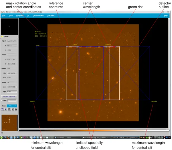
Once a field is defined, the mask can be initialized by pressing Init Mask in the LUCIFER menu. This action initializes the LUCIFER menu items, loads the instrument parameters from the ISF file, and draws a mask in standard configuration (N/1.8 camera, K-band filter, grating number 3). At this stage, the screen should look like in figure 3.1: On top of a fits image (or the source positions from a catalog) the 4 arcmin x 4 arcmin LUCIFER field (for the N1.8 and the N3.75 camera) is drawn as a white square. Inside this square two vertical white lines limit the central region (2.5 arcmin wide) of acceptable defocus (due to the deviation of the cylindrical mask from the focal sphere). 6 square reference apertures of 0.5 arcsec width are positioned close to the upper edge of the mask for alignment purposes. They are marked by the cyan labels #1 to #6. The small red rectangle close to aperture 6 indicates the area occupied by the mask ID number cut into the mask.
In the upper left corner of the SkyCat main window, the rotation angle of the mask and the mask cen-ter coordinates are indicated. Immediately afcen-ter mask initialization, the rotation angle is zero, and the mask center is identical with the image or the catalog center. By dragging the green dot at the mask center, the mask can be shifted across the field. By clicking the green dot with the center mouse but-ton, the mask rotates counter-clockwise in steps defined the Rotation Step sub-menu of the LUCIFER
LUCIFER LMS User Manual Issue 1.60 LBT-LUCIFER-MAN 030 9 @ @ @ @ @
mask rotation angle and center coordinates
B B B B B B B B B reference apertures A A A A A A A A center wavelength green dot detector outline C C C C C C C CC minimum wavelength for central slit
maximum wavelength for central slit
C C C C C C C C C C C
limits of spectrally unclipped field
Figure 3.1: Screen shot of SkyCat with a FITS-image loaded and a mask initialized in the default configuration (K-band filter, GRATING 3, N1.8 camera). The mask is centered on the image.
Config / Layout menu. When the shift key is pressed while clicking the center mouse button, the mask rotates clockwise.
In this situation, left clicking anywhere inside the white square creates a slit at the mouse pointer position with default parameters (4 arcsec long, 0.5 arcsec wide).
Caveat: Shift and rotate the mask before positioning any slits. Moving the mask will delete all slits!
3.1.3 Configuring the instrument
The white square is enclosed in a blue rectangle which indicates the spectroscopically usable detector area (spectra can extend beyond the field of view in dispersion direction). The size of this rectangle depends on the camera selected. The blue rectangle in figure 3.1 refers to the N/1.8 camera, for the N/3.75 camera the blue rectangle nearly coincides with the white square, and for the N/30 camera (not yet implemented) it occupies only the central 0.5 arcmin x 0.5 arcmin of the white square. The inner, vertical blue lines enclose the area of unclipped spectra. For a slit positioned within this area, the spectrum fits completely on the detector. If the slit is outside this area, its spectrum will be clipped on one side. The positions of these two blue lines depend on the camera, the filter and the grating selected. I addition, the line positions can be changed by modifying the extreme wavelengths and the center wavelength in the WaveLengthRange sub-menu of the Config / Layout menu.
LUCIFER LMS User Manual Issue 1.60 LBT-LUCIFER-MAN 030 10
area for a spectral range of interested (e.g., if only one line is to be observed). The two numbers close to the upper end of the blue lines indicate the central wavelength. Changing this number affects the grating tilt, which is limited to about±5 degrees. Central wavelengths which require a larger tilt are not allowed and will be ignored. The numbers close to the lower left and right corner of the blue rectangle are the (theoretical) extreme wavelengths imaged on the detector for a central slit (the actual wavelengths range may be smaller due to the band-filter used).
For better identification of the spectrally clipped areas, diagonal lines connect the corners of the blue rectangle indicating the usable detector area to the end points of he two blue lines limiting the spectrally unclipped area. For several instrument configurations, no unclipped area may exist. In this case, the blue diagonal lines change their color to red. If this happens, either choose a different instrument configuration or limit your wavelengths range.
The instrument configuration should be done in the following way:
1. Open the LUCIFER menu, click on the Config / Layout button and then on the dashed line in the sub-menu. This opens theConfig / Layoutsub-menu in its own window which does not close after each parameter selection.
2. Select your wavelength range by pressing one of the buttons in the Band Filter sub-menu. The optimum grating for this band filter is set automatically.
3. In case a different grating should be used, click the Grating sub-menu. The allowed gratings are high lighted. Some filters work only with one grating, e.g. for HK only GRATING 2 is available, for z only GRATING 1. For details on the gratings, please refer to the LUCIFER user manual.
4. Click the WaveLengthRange window to change the central wavelength and the desired upper and lower wavelength limits, if required.
5. Select the camera from the Camera sub-menu. Normally the N/1.8 camera is used for spec-troscopy.
6. Select the slit length and slit width from the Slit Length and Slit Width sub-menus (default values are 4 arcsec length and 0.5 arcsec width).
7. Close theConfig / Layoutwindow.
3.1.4 Reference Star Selection
Once the instrument and slit parameters are set, reference stars should be selected in the LUCIFER field of view. At least three reference stars are required to check and correct the telescope pointing and the instrument rotation angle. More than three reference stars will reduce the inaccuracies. Because the telescope pointing and the orientation of the instrument (the mask) on the sky, are derived from the reference star positions in the image, the reference targets should be taken from the same source (FITS image or catalog) as the science objects.
To select reference stars, click on the Reference Targets sub-menu, then select add . The white frame indicating the LUCIFER field of view becomes red, and an information window pops up; press theOK
button after you have read the text. Then an input window appears into which the coordinates of the reference star can be entered. In case a FITS image is available, press the Pick object . . . button. Another window appears which in its upper part shows a small area of the fits image around the cursor position. Move the cursor to a star in the fits image. When the star is close to the center of thePick Objectwindow, press the left mouse button. After a short time, a cross should appear at the center of the star, and its coordinates are displayed in the window. Now select theEnter Objectwindow and press Enter . A blue circle appears around the star, indicating that the reference star has been added to the list. Press the Pick object . . . button in thePick Objectwindow to select the next reference star.
LUCIFER LMS User Manual Issue 1.60 LBT-LUCIFER-MAN 030 11
In case the cross is not centered on the stellar image, press the Pick object button in thePick Object
window again, and try to position the mouse pointer closer to the star before clicking the left mouse button. If the stellar image is larger than the window, reduce the zoom factor by clicking on the smallzin thePick Objectwindow before starting another selection. To finish the reference star selection click twice the Close button in theEnter Objectwindow.
Reference stars must be positioned within the red square. No check is made when the star is selected, but the positions can be verified by pressing verify in the Reference Targets sub-menu. The reference and the guide star positions are checked automatically before saving a mask, and the result of this check is displayed in an information window. In case one of the check fails, the observation cannot be executed!
3.1.5 Guide Star Selection
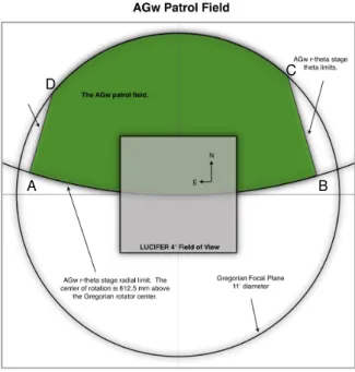
The procedure to select a guide star is the same as for a reference star. It is controlled by the Guide Stars sub-menu. When pressing the add button, a red polygon appears which indicates the guider patrol field. This field partially overlaps with the LUCIFER field. If possible, select a guide star out-side the LUCIFER field. Take into account that the pickup unit of the guide probe covers about 1 arcmin x 1 arcmin on the sky, and is mounted on a solid bar. Therefore, if the guide star is inside or close to the LUCIFER field, an area of this size will be vignetted, and reflections from the probe can be visible in the image.
At least one guide star is required, and selection of the guide star is in the responsibility of the observer at the LBT. It may be necessary to rotate the mask in order to have a guide star inside the guider patrol field.
3.1.6 Slit Positioning
Once LUCIFER is configured, the slit parameters are set, and the reference and guide stars have been selected the slits can be positioned on the mask. Slit positioning can be achieved in 3 different ways:
1. A left mouse click anywhere within the white square will create a slit at the cursor position. 2. Pressing the Center Slit button in the Config / Layout sub-menu opens thePick Object
win-dow known from the reference target and guide star selection. Within the white square, click the left mouse button, wait until the image in thePick Objectwindow moves with the mouse cursor, then drag the mouse until the source is located close to the center of thePick Objectwindow, release the mouse button, and wait until the source center position is indicated and the slit appears on the mask.
3. In case a catalog has been loaded, click on Auto-Slit in theLUCIFERmenu.Slits will be positioned in the blue rectangle (or the white square whatever is smaller), starting with source position 1 in the catalog. In case the spectrum of a new slit would overlap with an already existing spectrum, this slit will not be generated.
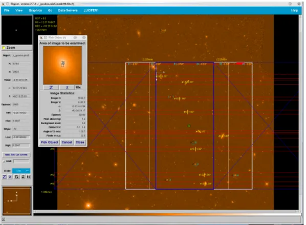
Fig. 3.2 depicts a typical situation for creating slits using theCenter Slitoption. The FITS-image is the same as in Fig. 3.1, but the mask has been shifted off-center, and the image has been magnified by pressing the Z button above the pan window in the lower left corner of the SkyCat window. The cyan circles numbered 1 to 5 are centered on the reference targets. The yellow circle number 1 is centered on the guide star.
Reference slits number 1 to 6 close to the upper edge of the mask are used for alignment checks and cannot be modified by the user. The red rectangle close to alignment slit number 6 indicates the position of the ID-number cut into the mask. No slits should be positioned between the reference slits and the upper edge of the mask to avoid interference with spectra from these slits and from the slits making up the ID-number.
Slits number 7 to 16 have been generated using theCenter Slitoption. ThePick Objectwindow shows the source on which slit number 16 has been positioned. Slit number 7 is outside the blue
rect-LUCIFER LMS User Manual Issue 1.60 LBT-LUCIFER-MAN 030 12
Figure 3.2: Screen shot of the slit generation process usingCenter Slit. The mask has been shifted, but not rotated relative to the image.
angle, its spectrum will be clipped on the red side. All slits are 1 arcsec wide, but their lengths and tilts have been set individually, e.g., to align the slit along the major axis of an object. The tilt of the major axis against the x-axis (horizontal in this case) is listed in thePick Objectwindow. The tilt of the slit is measured against the y-axis. The rotation angle of the slit is positive if it is rotated from the y-axis towards the x-axis.
Slit parameters can be modified by left clicking on the slit width label next to the slit image. In this case an entry window appears which lists the slit width and length in arcsec, the slit tilt in degrees, and the slit center position in mm from the mask center. When the Enter button in this entry window is pressed for the first time (even without changing parameters) two white arrows spanning a coordinate system are displayed, like the ones next to slit number 16 in Fig. 3.2. Their lengths correspond to 10 mm on the mask (in the telescope image plane), the arrows point towards the positive x- (horizontal line) and y-direction (vertical line). The lines should be helpful for changing the slit center position. The lines are deleted if the parameters of another slit are modified or if the image is redrawn (e.g. when zooming in or out).
Note that slit number 14 does not exist. It has been deleted, and the following slits are not renumbered. Slits can be deleted by either center clicking on the number label next to the slit, or by left clicking on one of the number labels at the edges of the spectral bars.
LUCIFER LMS User Manual Issue 1.60 LBT-LUCIFER-MAN 030 13
3.2
Basic Movements and Functionalities
The central green circle on the mask image (Fig. 3.2) has the function of handling the mask as a whole. In the following, the 2 mouse buttons (left, middle) are designated B1 and B2 . Their functions when clicking on the central green circle are:
• B1 : mark current mask position
• B2 : rotate LUCIFER1/2 (and hence the mask) counter-clock-wise on the screen. The default step-size is 5◦. The step-size can be controlled from the Rotation Step button in the LUCIFER1/2
Config/Layout menu.
• Shift B2 : rotate LUCIFER1/2 (and hence the mask) clock-wise.
• B1 and move: Changes telescope pointing position (and hence moves the mask)
The function of the right mouse button B3 is for measuring distances, as in the default SkyCat setup. Click the right mouse button to define a reference position, release the button, then drag the mouse, the angular distances between the actual cursor position and the reference position is displayed in arcsecs or in arcmin:arcsecs. To stop the measurement, press the right mouse button again.
Caveat:Rotating or shifting the mask deletes all slits! Therefore, first position the mask correctly, then select the reference and guide stars and finally position the slits.
Note:When large zooming is used, the green handling circle might be no longer visible on the canvas. In this case there are three possibilities:
• zoom out of the canvas using z
• drag the white rectangle in the lower left pan-window to scroll the canvas to the appropriate position • use the scroll bars of the canvas (only if SkyCat has been started with the scroll command line
option, as is done by lms.sh).
3.3
Reference Stars and Target Acquisition
The selection of appropriate reference stars within LMS will be the most important task to ensure that the science targets will be on the slits:
Reference stars have to be selected from the data set which is used for slit positioning.Before taking a MOS-spectrum, these reference stars are identified on the image taken during the target ac-quisition sequence. From their measured positions, the translation and rotation offsets are calculated and these values are used for telescope pointing correction and instrument rotator angle correction. At the LBT, finding the corrections and communicating them to the telescope is in the responsibility of the observer.
The absolute positions of MOS-slits (and thus the correct mask ID) are verified by mask images typically taken during daytime using the calibration source. These images will also be used to measure the position and rotation angle of the mask in the focal plane from the positions of the six reference slits along the top edge of the mask. It is the responsibility of the observer to check the correct alignment and positioning of the mask.
A general rule for the selection of reference stars: For MOS-observations it will be required to correct rotation and position offsets between the pre-image and the actual telescope pointing with high accuracy. A minimum of 3 reference stars are needed for this alignment, but we recommend that the user defines at least 5 reference stars. These should be widely spread over the field in which the science slits have been set. The procedure how to select reference stars is explained in section 5.7.
It is mandatory to select unsaturated point sources as reference stars which are bright enough to achieve a high signal-to-noise ratio within an integration time of typically 1 minute. There should be no brighter
LUCIFER LMS User Manual Issue 1.60 LBT-LUCIFER-MAN 030 14
star than the reference star within about 10 arcsecs and the reference stars should be at least about 10 arcsecs away from the edge of the field of view.
3.4
Finding Guide Stars for the LBT
LMS can be used to verify if there are appropriate guide stars in the patrol field of the auto-guider. When the Guide Stars add button is pressed, LMS shows a red contour limiting the guide probe patrol field. The guide stars have to be located inside this contour. Guide stars should not be selected from the region overlapping with the LUCIFER field (white square), because positioning of the guide probe inside the LUCIFER field causes vignetting and stray light. The useful guide star brightness range is 11 to 15 mag. In case no guide star is found, guiding is not possible and the observation cannot be carried out. Guide stars can be retrieved using on-line catalogs which can be overlaid on the FITS image. Press the button Data-Servers and Catalogs to access on-line catalogs. The relative position offset between guide stars on one side, and reference stars and science objects on the other side can be up to 10′′. Therefore, guide star positions can be taken from other sources than science objects and reference stars.
3.5
Instrument settings
After initializing the mask, LMS visualizes the focal field boundaries as a white square. Two white lines in north-south direction inside this square confine the 2.5 arcmin wide central area of small defocus (defocus is caused by the deviation of the cylindrical mask from the focal sphere). The back image of the accessible detector area on the focal plane is presented by a blue rectangle. The two vertical blue lines inside this rectangle confine the field within which slits can be placed without spectral clipping for a given camera/grating/filter combination. Slits can be set beyond this boundary, but some parts of the specified spectral range will be lost.
The default camera / filter / grating combination is: N/1.8 camera / Ks band filter / GRATING3; the selec-tion of these elements is done from the Config/Layout menu (for details see secselec-tion 5.10). Selecselec-tion of a band filter will automatically select the optimum grating and disable the radio buttons for gratings not available with this filter.
The Help Grating Info info shows allowed filter/grating combinations together with the spectral orders, the band filter center wavelengths, and the 50% limits, as read from the Instrument Summary File (ISF). Please note that for some combinations, the spectrum does not fit on the array. In this case the two blue boarder lines limiting the unclipped area are connected to the corresponding array edges by red diagonals, indicating that no unclipped spectrum can be recorded. (To avoid confusion, the diagonal lines are displayed only if Labels is activated in the LUCIFER1/2 Config/Layout menu). A smaller wavelength range can be chosen via the Config/Layout WaveLength Range menu. This choice has no physical effect, but re-draws the border lines of the unclipped area. LMS recognizes if the user-defined wavelengths limits are outside the filter band, and replaces these values by the default band limits. The WaveLength Range menu also permits selection of the center wavelength (the wavelength at the slit image). This setting has a physical effect in that it tilts the grating to move the selected wavelength to the slit image.
Hint:Using theConfig/Layoutmenu from theLUCIFER1/2menu is rather tedious because it closes after each setting. This can be avoided by clicking on the dashed line at the top of theConfig/Layout
menu. The click creates a stand alone configuration window which stays open until explicitly closed by the user.
LUCIFER LMS User Manual Issue 1.60 LBT-LUCIFER-MAN 030 15
3.6
Creating Slits
Beside the basic key bindings for mask positioning (see section 3.2) and the LUCIFER menu items, LMS provides the following bindings:
• press B1 to create a MOS-slit within the LUCIFER field (white square)
• press B1 on the slit number label at the edge of the detector contour (blue rectangle) to purge the slit
• press B1 on the slit width label to configure this slit (width, length, tilt, center position in x and y) • press B2 on the slit number label next to the slit to purge the slit
Presently two MOS slit types are supported STRAIGHT (=rectangular slit, optionally tilted with respect to the dispersion direction) and CIRCLE (= just a circle).
Slit positions are not checked for plausibility, but
1. slits are created only if the mouse pointer is inside the LUCIFER field (white square), 2. the mouse pointer is outside the green central dot,
3. the mouse pointer is outside the inner circle around a reference star,
4. the mouse pointer is outside the red rectangles indicating the areas occupied by the spectra of already created slits.
This has the following consequences:
1. If a slit is generated close to the edge of the field of view, part of the slit might be outside the field. 2. If a slit is created close to the spectrum of another slit, the spectra can overlap.
3. When the slit position or the slit length is modified via the slit parameter entry form window, the slit might be shifted outside the field, or spectra might overlap.
It is in the responsibility of the user to check that the slits are inside the field of view and that spectra do not overlap.
Center Slit option:The center slit option selectable from the configuration menu will significantly im-prove the slit positions for point sources and other relatively compact targets. A SkyCat feature with the centroid algorithm: a single click on the target and the algorithm might fail. Click somewhere with the left mouse button B1 , hold the button while moving the mouse, wait until you see the target in the center of thePick Objectwindow and release the mouse button now. Centering may not be possible if the object extends beyond thePick Objectwindow. In this case, reduce the zoom factor of this window until the source is fully inside the window.
Slits behind the green circle or on reference stars:The left mouse button while used on the location of the green circle is defined to move the mask. It is only possible to put a slit behind the green circle with theCenter Slitfunctionality as described above - click somewhere outside the green circle, keep the left mouse button pressed while moving the mouse behind the green circle, wait until you see the target in thePick Objectwindow and release the mouse button. The same procedure applies to the inner circle around a reference star. In case a slit is to be placed on a reference star, activate theCenter Slitfunctionality, click outside the circles around the reference star, and when the image in thePick Objectwindow becomes active, move the mouse pointer on the source.
Modifying slit parameters:The last two lines of the slit parameter entry form display the slit center position (in mm on the mask measured from the mask center). They are meant for minor adjustments of the slit position. A small coordinate system next to the slit appears when the Enter button in the slit editing menu is pressed for the first time (even if no changes have been made). The lengths of the two arrows correspond to 10 mm on the mask. The arrows point in positive x (parallel to the dispersion direction) and y direction. This coordinate system should help to estimate the required changes in the slit center position. The coordinate system disappears if the zoom factor is changed or the editing menu
LUCIFER LMS User Manual Issue 1.60 LBT-LUCIFER-MAN 030 16
of another slit is opened. No plausibility check is implemented for the modified slit position. While slits can be created only inside the white square limiting the FOV, they can be placed outside the FOV by changing their positions in the slit menu. Be careful to stay within the white square!
Auto-Slit option:In case a catalog has been loaded into SkyCat, selecting theAuto-Slititem in the
LUCIFER1/2automatically places slits on the sources listed in this catalog which are located inside the blue rectangle defining the spectrally unclipped area. In case the unclipped area is larger than the LUCIFER field, slit positions are limited to the field. Slits are placed starting with the first catalog position inside the blue rectangle. The program then goes down the list and checks for each source if it is inside the blue rectangle. If so, the program checks if the spectrum from the slit on this object would interfere with other spectra. If not, the slit is created. No other criteria are involved in slit placement. Therefore, high priority objects should be placed at the top of the catalog. For details on how to set up a local catalog refer to chapter 4.
Slit constraints
1. Individualslit lengths are restricted to 20 arcsec for mechanical stability reasons. It is however not excluded to produce larger multi-slits or unusual slit geometries by punching several individual slits next to each other - with some space in between. However, such large multi-slits may cause mask sheet bending and are thus to be discussed with the observatory staff.
2. In LMS, thenumber of slitshas been limited to 200. In practice, this limit should never be reached, because it implies an average slit length of about 1 arcsec, which is impractical.
3.7
Saving Masks
When all slits have been created, the mask configuration has to be saved. At this point three files, all with the same name, but with different suffixes are created:*.lms, *gbr, *.epsf.
Thelmsfile contains the information for telescope pointing and instrument rotation, all slit parameters, including slit center coordinates in WCS units (not for the 6 reference apertures) and in mask coordinates (mm x and y), the WCS coordinates of the reference targets and of the guide stars, as well as the LUCIFER configuration parameters. This file can be reloaded to restore the session. It is also used as input to produce the telescope control system script for observation with this mask.
Thegbr file contains the information required for cutting the mask and the slits, including the mask contour, the holes for mounting of the mask, and the mask ID. Freeware programs likegerbvare available on the web for viewing this file. Visual inspection can be useful to check the masks before cutting or to clarify the mask identity by comparing an image taken through the mask with the gerber file image. Theepsffile contains a mask image for direct viewing in case no gerber file viewer is available. This image does not contain the mask ID!
File name conventions:Thelmsfile has the formatmos<d>.<ddd>.<project>.lms. In this string, the firstdis 1 for LUCIFER 1 and 2 for LUCIFER 2,dddis a 3-digit counter which is incremented by 1 each time an lms file is saved (leading zeros are omitted),projectis an up to 8 characters long string which can be set in the LUCIFER1/2 Config / Layout ProjectName menu. If no project is specified, the file name reduces tomos<d>.<ddd>..lms.
Mask name and mask identification number:Each mask has a unique identification number (ID, lms keywordINS.MASK.ID), and a mask name (lms keywordINS.MASK.NA). The ID is cut into the mask sheet. When saving a mask setup, a third keywordINS.MASK.NAIDis created and also stored in the
lmsfile. The format of its value isMdddcccccccc+ddddddwhich is equivalent toM< INS.MASK.NA
>+< INS.MASK.ID >. Starting from left, the sub-stringddd contains the three digit number of the LMS internal counter, cccccccc is the up to 8 char long string containing the user-defined project name, both of which also appear in the file names. dddddd is a six digit random number between 900 101 and 999 999 representing the mask ID (values between 900 000 and 900 100 are reserved for technical masks). When a mask has been cut, it can be identified by this ID.
LUCIFER LMS User Manual Issue 1.60 LBT-LUCIFER-MAN 030 17
Before the mask is saved, a project name should be defined. Otherwise the file names differ only by the three digit counter, and it can easily happen that files submitted from different groups have the same names. This can cause confusion when the lms files have to be assigned to the corresponding masks.
Chapter 4.
Local Catalogs
In case no FITS image is available for slit positioning, a local catalog can be used instead. Catalogs can be downloaded from the web or generated by the user. SkyCat provides tools for downloading, storing, and editing catalogs.
In this chapter we first describe the catalog format required by SkyCat and LMS, then we explain how to set up a local catalog from a remote catalog query, and finally we elaborate on generating catalogs from the scratch.
4.1
Catalog Format
Here we give a concise description of the catalog format. A detailed description can be found in chapter 2 of the Astronomical Catalog Library User Manual (4).
Local catalogs are implemented as simple ASCII files intab tableformat. This is the same format that is used to return query results from remote catalogs. The results of catalog queries are always returned in the format of atab separated tableof values. The column headings are separated from the data by a dashed line:
Title # comments Keyword: value
...
ID RA DEC MORE PREVIEW
-- -- -- ----
---NGC5457-FD2 14:02:22.489 +54:17:58.29 M=http://... P=http://... NGC5457-FLD2 14:02:22.489 +54:17:58.29 M=http://... P=http://...
... ... ... ... ...
Lines starting with#are considered as comments and are ignored. Keyword: valuecombinations specify the catalog from which the data are extracted, non-standard usage of columns, and how to plot the sources. This information is used by SkyCat.
The line containing ID, RA, DEC, ... specifies the meaning of the values in the columns listed below and is mandatory. The keywords have to be tab separated. For usage with LMS, the first three columns are required. Any number of other source parameters (e.g. magnitude, redshift, size, priority) can be included here, but have no effect for usage with LMS. The columnsMOREandPREVIEWhave special meanings, and are not visible in the query result window. The two columns contain HTTP URLs pointing to locations providing more information on the source and images, respectively. In case the columns are not empty, the buttons More Info and Preview below the list window are activated if the corresponding source is highlighted. Under SkyCat 2.7,More Infotries to launch Netscape, which is no longer available on most systems.
The column headings are separated from the data by a dashed line. For theAuto-Slitfunction, LMS uses the first three columns only. Again the columns are tab separated. TheID can be any unique character string composed of alphabetic characters, numbers, and underscores.RAandDECare listed in hh:mm:ss.ss and ±ddd:mm:ss.sss format for equinox J2000. The valid keywords and formats are summarized in the following table:
LUCIFER LMS User Manual Issue 1.60 LBT-LUCIFER-MAN 030 19
Meaning Keywords accepted by LMS Value
unique identification character strings containing catalog source name/number ID, Id, name, target, star, object
right ascension RA, Ra, ra position in format hh:mm:ss.ss, J2000 declination DEC, Dec, dec position in format±ddd:mm:ss.ss, J2000
4.2
Creating a Local Catalog from a Web Search
The simplest way to create a local catalog is to search one of the catalogs available on the web. These catalogs are accessible from SkyCat via the Data-Servers Catalogs menu which displays a list of catalogs. Clicking an item of this list opens a query window. In case a FITS image has already been loaded, press the Set From Image button in the window to set the search area in the catalog (defined by the center coordinates and the maximum radius). In case no FITS image has been loaded, the center coordinates and the search radius (in arcmin) have to be entered manually. The minimum radius should be set to zero, otherwise an annulus between minimum and maximum radius is searched. The limiting object magnitudes and the maximum number of objects listed can also be defined (entering these numbers is not mandatory). Once the search area and the other parameters are defined, press the Search button to start the query.
A list of sources with names, coordinates and additional parameters appears (the additional parameters are catalog specific), and the source positions are marked either on an empty virtual field or on the FITS image. To see the sources symbols, it may be necessary to adjust the image brightness by dragging the mouse cursor along the color bar below the main window. In case you are satisfied with the source list, save it as a local catalog by opening the File menu in the query window and then select Save as . . . . Use the extensioncatto save the list in the PREP directory.
In case only a few objects from a long source list are plotted, have a look at the Options Set Plot Symbols . . . menu in the query window. In the upper part, the plot symbols window lists the parameters used to define plot criteria, the symbol plotted, and other parameters (symbol size, condi-tions, etc.). Several criteria can be combined and attributed to different plot symbols. Usually, the size of the plot symbol is related to the source brightness, e.g. by entering a relation like(20 - $Fmag)*3in the lineSize. In addition, special conditions can be selected for plotting a source. E.g.,$e == 1in the lineConditionsprevents the plot of sources with an eccentricity differing from one. All these values can be set and modified by the user.
Remark:The syntax for calculations and conditions is the standard Tcl/Tk syntax, i.e., the value of a variableeis$e.
The second menu item in the query window, Edit, works only on local source lists. Therefore, a list loaded from a catalog server, has to be locally stored and then reloaded before it can be edited. Editing includes removing of a selected source, adding new sources, and editing parameters of a selected source. New sources can be entered by typing their coordinates and ID into the input window. Alternatively, in case an underlying FITS image is available, thePick Objectmode can be used in the same way as for reference target and guide star selection. Unfortunately, the coordinates are not automatically transferred from thePick Objectwindow to theEnter objectentry form. However, the values can be copied and pasted between the two windows.
The LUCIFER menu in the query window can be used to add magnitude and priority columns which have no effect in the present LMS version. This may change in upcoming versions.
4.3
Building Your Own Catalog
With the format information from section 4.1 it is relatively simply to build a local catalog. Just execute these steps:
LUCIFER LMS User Manual Issue 1.60 LBT-LUCIFER-MAN 030 20
1. In a text editor, create a new empty file.
2. Type in the row with the header information for the catalog. At least three tab separated keywords (e.g. ID, Ra, Dec) are required, more can be added, but have no effect in LMS.
3. Type the next line which contains only dashes.
4. Enter the tab separated parameters for the first source: a name and the coordinates in the format specified in the table at the end of section 4.1.
5. Enter the tab separated parameters for the other sources, one source per line. 6. Save the file with the extensioncatin the PREP directory.
Now this local catalog can be loaded into SkyCat. Start LMS as usual, then open the menu Data-Servers and Local Catalogs . In this menu click the last line Load from file . . . . In the file selec-tion window, go to the PREP directory and select your catalog file, then press the OK button, the catalog is loaded and the catalog query window containing the source list pops up. If you load the catalog for the first time, you will not see any source positions plotted. The reason is that no plot symbol has been defined in the catalog header.
To define the plot symbols proceed as follows:
1. In the catalog window click the Options menu and then Set Plot Symbols . . . .
2. A new window with the titlePlot symbols for<filename>appears, and a message pops up that no plot symbols have been defined for this catalog.
3. The uppermost sub-window lists the columns used for plotting and the plot parameters assigned to these columns. The window should be empty at this stage.
4. In the columns window mark a column in the Not Used field and move it to the Used field by clicking the lower blue arrow. More than one columns can be selected. Plot conditions and symbol size can only be defined for columns in theUsedfield.
5. Use the default plot symbol (circle) or select a different symbol by clicking on the blue bar in the lineSymboland then select one of the symbols displayed.
6. In the same way select the symbol color by clicking on the lineColor, or keep the default value (black and white) which is best suited for colored background.
7. Next define the symbol size by entering a number or an expression in the line Size. You can always use a number, a typical value is 3 to 10, depending on the image size. In case a magnitude column has been chosen, the plot symbol size can be defined by the magnitude. For example, if mv has been chosen, the plot symbol size can be defined as (15 - $mv), which plots a zero magnitude star as a circle with diameter 15, and a ten magnitude star with diameter 5. Objects fainter than 15 magnitude are not plotted in this case. The default units for the symbol size are image pixels. 8. In case a column like mv has been selected for plotting, a condition should be specified to avoid
error messages in case no magnitude is listed for a source. For example type ($mv<15) in the line
Condition. Several conditions can be combined, like ($mv != “ ”) && ($mv<15), where the first conditions prevents application of the plot size expression to symbols with undefined mv (which causes an error message). Conditions can be defined only for columns listed in theUsedfield. 9. When all required parameters have been defined, press the Add Symbol button. The plot
param-eters should appear in the uppermost sub-window.
10. Press the Apply button. The symbols should be plotted on a virtual field (or on a FITS image if loaded).
LUCIFER LMS User Manual Issue 1.60 LBT-LUCIFER-MAN 030 21
12. Save the settings using the File Save as . . . menu of the catalog window. You can overwrite your original catalog, source data have not been changed, but several lines containing the catalog file name and the plot parameters have been added to the header.
All plot parameters can be modified at any time via the Set Plot Symbols . . . sub-menu.
4.4
Local Catalogs and Auto-Slit
As already mentioned, theAuto-Slit function can be used to position slits automatically on catalog po-sitions. First you have to load a local catalog or do a query on one of the catalogs available on the web via the SkyCat menu. Then the mask has to be initialized, and positioned in the field.
Slits can now be positioned on the catalog sources by pressing the Auto-Slit button in theLUCIFER menu. The program goes through the catalog starting with the first source, it first checks if the source is inside the white rectangle of the LUCIFER field. If this is the case, a slit is positioned on the source. For the following sources, the same position check is made. If the source is inside the white rectangle, another test is made to check if the spectrum from this source would overlap with spectra from already positioned slits. If this is not the case, a slit is positioned on this source, otherwise the source is skipped. After entering reference targets (from the same catalog) and guide stars, the mask can be saved. At this instance, the objects on which slits have been positioned are deleted from the catalog loaded into SkyCat (but not from the original catalog) and from the SkyCat main window. In the lms file, the catalog source names are entered behind theINS.TARGxxx.NAMEkeyword of the corresponding slits.
In case there are sources left in the field, you can shift the mask image so that these sources are inside the white rectangle. After dropping the mask at the new position, the previous slits are deleted from the image, and you can press the Auto-Slit button again. New slits are then positioned on the remaining sources. After entering reference targets and guide stars this masks can also be saved. Again, the sources on which slits have been positioned are deleted from the catalog and from the screen.
This procedure can be continued until the catalog is empty. The session can be interrupted after saving a mask. In this case, the last version of the catalog should be saved under a new name (using the File Save as . . . menu in the catalog window). This catalog file can be reloaded later to continue the slit positioning session.
A known problem with Auto-Slit:
When slits are positioned usingAuto-Slit, and reference targets and / or guide stars are positioned by typing their coordinates into theEnter Object window, some slit images and circles around reference and guide stars are slightly offset relative to symbols representing the catalog objects (by less than 0.5 arcsec). This seems to be related to the pixel size of the internal graphics screen (relative position changes with zoom) and does not affect the correct positioning of slits and does not affect the accurate slit positioning. The slit coordinates stored in the lms file are identical to the object coordinates listed in the catalog.
Chapter 5.
LMS Menu Reference
This section gives a comprehensive description of all pull down menu items in the LMS menu and its sub-menus.
LUCIFER1/2
Init Mask section 5.1 Reset Mode section 5.2 Load Setup section 5.3 Quit Mode section 5.4 Auto-Slit section 5.5 Save Setup section 5.6 Reference Targets section 5.7 Guide Stars section 5.8 Status Panel section 5.9 Config/Layout section 5.10
5.1
Init Mask
The mask can only be initialized if a WCS is defined, i.e., if a FITS image or a catalog has been loaded. Pressing this button plots the focal field (white square) and the current instrumental mask over the sky image or the catalog field. The two white lines within the square limit the area of acceptable defocus due to the deviation of the cylindrical mask from the focal sphere. The closely spaced red lines near the top of the field indicate the area in which the six reference apertures (0.5′′×0.5′′) are positioned. The mask ID-number, indicated by a red rectangle is also cut in this area. The blue rectangle is the back projection of the accessible detector area onto the focal plane, its size changes with the camera selected. For the two blue lines inside the rectangle refer to the Labels option in the Config/Layout sub-menu. The mask is initialized and oriented according to the underlying FITS image (the 6 reference slit are aligned along the northern edge of the mask, slit number 1 is next to the eastern edge). The rotator angle (= (-1)×position angle on the sky) is zero. The orientation of the FITS image is indicated in the small window on the lower left of the SkyCat GUI.
5.2
Reset Mode
Pressing this button deletes all slits, but keeps the reference targets and the guide stars.
5.3
Load SetUp
This menu item configures the initialized mask by reading all relevant telescope, instrument, and mask parameters from an*.lmsfile which has been saved during a previous session. Be careful to load the
setup for the FITS image or catalog in use. In case the wrong setup file is read, no error message is issued, but normally the mask image is no longer visible, because it is located outside the sky area displayed in the SkyCat window. The name of the FITS image associated with an*.lmsfile is listed in
the comment lines at the top of the*.lmsfile.
LUCIFER LMS User Manual Issue 1.60 LBT-LUCIFER-MAN 030 23
5.4
Quit Mode
This menu item deletes the mask and de-activates all LMS features.
5.5
Auto-Slit
The automatic positioning of MOS slits requires a catalog which lists at least source names and source positions. Slits will be positioned on the catalog positions, even if an FITS image with deviating source positions has been loaded together with the catalog. Remember to take the reference targets also from the catalog, and not from an underlying image!
Automatic MOS slit positioning works for several on-line catalogs like GSC, SIMBAD, NTT archive, USNO, as well as on user-defined catalogs. These catalogs have to be compliant with the require-ments for astrometric accuracy (section 2.4.1) and for target catalogs to be used with SkyCat and LMS (chapter 4).
The Auto-Slit program takes the current mask coordinates (RA and DEC) and position angle (PA). Start-ing from the top of the catalog, the program searches for targets located inside the blue rectangle defin-ing the area of unclipped spectra (or within the white square limitdefin-ing the field, whichever is smaller). If a target inside the blue rectangle is found, the program checks if the spectrum of a slit centered on this target interferes with the spectrum of any of the already existing slits. If this is not the case, the slit is positioned on the target, otherwise the target is skipped.
Auto-Slit does not move or rotate the mask. Therefore, the best mask position and orientation has to be set before starting the Auto-Slit function.
Since Auto-Slit positions the slits on the targets in the order they appear in the catalog, this order be-comes important for crowded fields. High priority sources should be positioned at the top of the catalog.
5.6
Save
This saves the current mask settings and creates three files in the $INSROOT/.lms/SET directory, using the syntax:<mode>.<counter>.<projectname>.<ext>where
• <mode>is alwaysmos1ormos2in LMS
• <counter>is incremented with each save operation in order to avoid overwriting previous set-ups of the same project name
• <projectname>is an 8 character user defined name. See section 5.10.3 • <ext>is one oflms,gbr,epsfwhere
– lmsis used by LMS to re-load a set-up, and for observation preparation, since it contains telescope pointing and slit positions,
– gbrcontains the slit information in Gerber format, and is used for mask cutting,
– epsfcontains a mask image, including the mask contour, centering slots, reference aper-tures, and science slits, but not the mask ID-number.
Please keep all output files produced by LMS; they could be useful later if a problem occurs during observation.
During the save procedure, in a first step the reference targets are verified and the user is asked again if the set-up should be saved. Follow the recommendation and don’t save set-ups that will fail at the LBT. At least three, but for better alignment accuracy five to seven reference sources must be specied before saving the mask.
LUCIFER LMS User Manual Issue 1.60 LBT-LUCIFER-MAN 030 24
5.7
Reference Targets
MOS target acquisitions have to be aligned using reference stars. Select up to 10 reference targets, ideally close to the slit positions. Reference targets can be specified at any time during an LMS session, but no longer during the save sequence. Press LUCIFER Reference Targets add to add reference targets. Purge reference targets by a comma separated list (e.g. 7,3) in the purge menu. The reset button erases all entries in the reference target list.
Selected reference targets will be highlighted via a cyan circle. The parameters of the chosen reference targets will be shown in thePick Objectwindow. To exit the selection process press the button Close in theEnter Objectwindow twice.
The sub menus are
• plot to plot the reference targets on the screen • show to list the reference targets and their positions
• add to add further reference targets. The forbidden area for reference target selection is outside the red square (which is essentially the contour of the LUCIFER field of view).
• purge to purge individual reference targets from the list; e.g. enter 1,4 to purge targets #1 and #4 • verify to check that all reference targets can be handled by LUCIFER
• reset to delete the complete list of reference targets
5.8
Guide Stars
At the LBT, the observer has to provide the guide stars for his observations. For this purpose, the menu item Guide Stars has been added. This menu has the same sub-menus as the Reference Targets menu, and they work in the same way. However, the guide stars selection procedure is quite different from the reference star selection procedure for the following reasons:
1. Since the guide stars are used for tracking only, the relative accuracy between slit and reference star positions on one side, and the guide star positions on the other side is not stringent (offsets of the order 10 arcsec are allowed). Once the guide star has been found, the reference objects can be aligned by telescope offset and instrument rotation. This implies that guide stars can be extracted from different sources than science objects / reference stars.
2. Guide stars are not observed by LUCIFER, but by the AGW (auto guider and wavefront sensor unit). Therefore, although the guider can pick up stars in the LUCIFER field, the guide stars should be located at least 1 arcmin outside the LUCIFER field to avoid vignetting and stray light from the auto-guider..
3. The auto-guider rotates with LUCIFER on the instrument rotator, and therefore the guide star field is fixed relative to the mask. Therefore, if no guide star is located north of the mask, rotate the mask until a guide star is above its ”upper” edge to avoid vignetting by the probe.
4. Brightness range for guide stars: 11 to 15 mag.
5. For each pointing, one guide star is required. For small offsets, two pointings can share the same guide star as long as it stays within the guider patrol field.
5.9
Status Panel
The button Status Panel creates a top level window showing the current status of the LMS session. The contents of the three fields