O R I G I N A L R E S E A R C H
Open Access
Optimum coordination of directional
overcurrent relays for combined overhead/
cable distribution system with linear
programming technique
Sarang V. Khond
*and Gunwant A. Dhomane
Abstract
Heavy fault currents flow in the event of fault at the loads connected in distribution system. To protect these loads, circuit breakers and relays are required at appropriate places with proper coordination between them. This research paper focuses on finding optimum relay setting required for minimum time to interrupt power supply to avoid miscoordination in operation of relays and also investigates effect on time multiplier settings (TMS) of directional overcurrent relays in a system with combined overhead lines-underground cables. Linear programming problem (LPP) approach is used for optimization. It is interesting to know the quantitative variations in TMS as the underground cables have different characteristics than overhead lines.
Keywords:Dual simplex method, Linear programming, Optimization, Overcurrent relay coordination, Power
distribution system
1 Introduction
Shunt faults occurring in power distribution systems in-creases current suddenly. This sudden increase in the value of current is a positive indication that fault has occurred in a system. In order to isolate a faulty section from healthy section, protection schemes are used in power systems. The overcurrent protection schemes are most popularly used for protection of power systems [1– 3]. In some protection schemes overcurrent relay protec-tion is the only protecprotec-tion scheme provided in networks. Each primary relay protects its specific zone. If primary relay fails to isolate faulty section the backup protection relay is provided to clear the fault. Generally power sys-tem has a number of equipments and a number of pro-tection relays in order to provide propro-tection to whole system under consideration. Therefore coordination be-tween relays plays an important role in protection schemes. If primary and backup relays are not in appro-priate coordination with each other malfunctioning will take place in operation of primary and back up relays.
Hence coordination in operation of overcurrent relays play a vital role in designing appropriate protection schemes for any power system network [4,5].
As the size of network increases, to obtain proper overall coordination between large number of primary and back up relays becomes a complicated problem. Hence, along with conventional methods for optimization, Artificial Intelligence based methods like Teaching Learning Based algorithms, Fuzzy logic, nature inspired algo-rithms (NIA), expert systems rules consideration, par-ticle swarm optimization (PSO), Honey Bee algorithm, Harmony search algorithm, Artificial Bees colony etc. are reported by various researchers to optimize co-or-dination of both directional and non directional over-current relays [6,7].
In the radial power system with only one source of generation there is flow of fault current and load current in only one direction. In case of directional relays being used, they will operate in the event of flow of fault current in the specified direction of trip-ping and hence do not need coordination with the re-lays which are behind them. However coordination is necessary in primary and backup relays, if primary
© The Author(s). 2019Open AccessThis article is distributed under the terms of the Creative Commons Attribution 4.0 International License (http://creativecommons.org/licenses/by/4.0/), which permits unrestricted use, distribution, and reproduction in any medium, provided you give appropriate credit to the original author(s) and the source, provide a link to the Creative Commons license, and indicate if changes were made.
* Correspondence:[email protected]
relay fails to operate, back up relay must operate to isolate faulty section from healthy section. Also in radial power systems with combined overhead lines-underground cables, the coordination in primary and backup directional overcurrent relays becomes essen-tial due to high charging current and capacitance of underground cables. With increased capacitance, the charging current of underground cable also increases, which may be as high as significant fraction of the load current. This imposes limitations on minimum relay settings [8, 9].
When the mode of operation is changed such as power system with more than one source of generation or a ring main system, there is flow of fault current and load current in both directions. The relays used in pro-tection schemes of such a system are thus subjected to fault currents flowing in both directions hence combin-ation of directional and non-directional overcurrent re-lays is required to be placed at appropriate positions in such protection schemes.
The directional relays will have their tripping direction away from the respective bus. The actual operating time for each directional and non directional relay is decided by considering the operating time of preceding relay, op-erating time of circuit breaker associated with preceding relay and the overshoot time of the relay which is under consideration.
With non directional overcurrent relays being used in such systems, coordination in relays is required between the relays which are located at the remote end of the line along with the relays behind them.
With the above mentioned concept kept in view for coordination between the relays, the optimization prob-lem can be formulated which can be solved by linear programming technique [8].
Thus for distribution networks with combined over-head lines-underground cables, designing the optimum relay coordination scheme using directional overcurrent relays can be considered as a constrained optimization problem which are solved as linear programming prob-lem with constraints. Many methods like simplex; dual simplex or two phase simplex technique can be used to solve such problems.
In this paper IEEE 13 bus radial distribution test feeder is considered for optimum relay coordination between pri-mary and backup directional overcurrent relays. This test feeder offers variety of interesting features. The operating voltage is 4.16 kV. The nodes are separated with moderate distances with adequate load. Thirteen nodes are intercon-nected through ten overhead and two underground line sections which constitutes a combined overhead/cable dis-tribution system. Feeder consists of a voltage regulator, a 115/4.16 kVΔ-Y transformer, 4.16/0.480 kV Y-Y step down transformer is interconnected. Loads are unbalanced with
changing phasing configuration between nodes. It also in-corporates eight unbalanced spot loads and two distrib-uted loads.
The model is simulated in MATLAB without voltage regulator and distributed loads for further analysis.
The directional over current relays are considered in protection scheme as load and fault current will flow in only one direction due to single source generation.
As many protection schemes use only over current relay protection schemes, this paper investigates the var-iations in calculated and optimum TMS values of over current relays if underground cables are interconnected. The underground cables have different characteristics when compared with overhead lines like high capaci-tance and high charging current. The effect on variations in relay settings due to combined distribution system is presented in results section at the end.
2 Coordination of overcurrent relays in radial power system
As soon as shunt fault occurs on a power system it is sensed by both primary and backup relays. The primary protection relay will operate first because its operating time is set lesser than that of the backup protection relay.
Figure1shows single line diagram of IEEE 13 bus dis-tribution test feeder. As only one generation source is present this system it can be considered as a radial dis-tribution system.
If fault occurs at point A on load at bus 646, primary relay R1will operate first. Let the operating time of R1is
set to 0.1 s. If primary relay R1fails to operate, back up
relay operates after 0.1 s.The backup relay R2 will
oper-ate after a delay of time duration of 0.1 s and the time duration equal to the operating time of circuit breaker (CB) at bus 646 and the overshoot time of relay R1. This
delay in operation of both the relays is required for maintaining the selectivity between relays R1and R2.
Similarly relay R3will act as backup relay for R2.
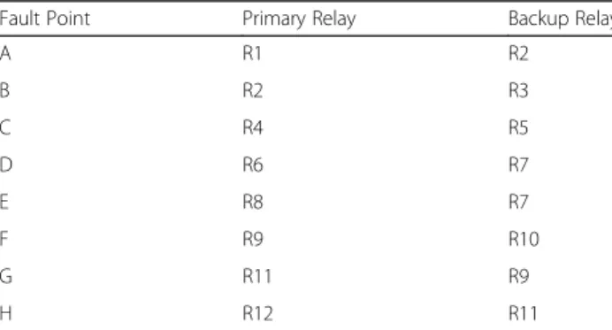
Over-all relay coordination scheme for the entire distribution system as indicated in Fig.1is represented in Table1.
3 Relay coordination problems
MinimizeΣWiTik ð1Þ
Where:
Wi- A coefficient which is generally set to 1.
Tik- Operation time for relay Ri when fault occurs in kth zone in the power system [10–14].
Therefore directional overcurrent relay coordination problem in electrical distribution systems can be consid-ered as an optimization problem, in which sum of oper-ating times of all relays in system is to be minimized under the given values of constraints [11,12]:
Coordination criteria
TnkTik≥•T ð2Þ
Where:
Tnk- Time required for operation of first backup relay Ri if a fault occurs in kthzone of power system.
•T- Time interval for coordination between primary and back up relays.
This duration is required for maintaining proper select-ivity between primary and backup relays. Coordination time interval between two relays has value 0.5 s [1].
Bounds on the settings
TMSimin≤TMSi≤TMSimax ð3Þ
Timin≤Ti≤Timax ð4Þ
Where:
TMSi- Time multiplier setting of relay Ri Ti-Operating time of relay Ri
Relay characteristics
Assuming that all relays are identical and have normal IDMT characteristics, the equation for operating time of relay is given by [10–14]:
Ti¼λ ðTMSiI Þ
Is γ −
1
ð5Þ
Where:
I- Input current Is- Setting current.
For normal IDMT relay characteristics,
λ- A constant with value taken as 0.14
γ- A constant with value taken as 0.02 [1]. Fig. 1Relay coordination diagram
Table 1Primary and Backup Relay Pairs
Fault Point Primary Relay Backup Relay
A R1 R2
B R2 R3
C R4 R5
D R6 R7
E R8 R7
F R9 R10
G R11 R9
As the values of pickup currents for all relays are ob-tained using data from system, Eq. (5) becomes
Ti¼ðαiTMSiÞ ð6Þ
Where:
αiis λ I Is
γ− 1
In general, the equation for operating time for normal IDMT relay can be expressed as:
TR¼ ð0:14TMSÞ PSM
ð Þ0:02 −1
Where:
PSM¼ I Is
Now by substituting the value ofTiobtained from Eq. (6) in Eq. (1), the objective function for optimization becomes
MinimizeΣðαiTMSiÞ ð7Þ
Where αi is known and values of TMSi can be deter-mined by using any one of the LPP method. In this paper dual simplex method is used for optimizing the problem.
Integration with renewable energy sources is essential for economical operation of power grids. However, such integration, changes the load flow in the network which may affect the overcurrent (OC) relays settings. Due to increased flow of the current through lines with such en-ergy sources will result in operation of OC relays even during normal conditions of the network. Also, proper OC relay setting becomes difficult as the generation of renewables depends on the weather conditions. It is ob-served that integration of Photo voltaic (PV) sources makes OC relays to operate without intention due to changes in magnitude and/or direction of current through the relays [15].
To handle such problem in the networks, two strat-egies are commonly adopted. In first strategy, renewable generation is disconnected from the network on occur-rence of fault. The second strategy permits such energy sources to remain connected even if fault occurs. Both the strategies are based upon standards developed by IEC and IEEE. As per the IEEE 1547–2003 Standard: Interconnecting Distributed Resources with Electric Power Systems, Distributed Generations(DG) are re-quired to be disconnected immediately when a fault oc-curs in the distribution networks. According to second
strategy, the DG is enabled with Fault Ride Through capability (FRT) to avoid disconnection due to occur-rence of faults in the network. FRT is achieved by delay-ing the trippdelay-ing time of the protection devices with the only intention of avoiding unnecessary disconnection of DG sources by riding through the very short time inter-val of disturbances. For DG of PV type, FRT capability varies from country to country. In most of the countries, allowable short duration of faults is not more than 150 milliseconds [16].
4 The dual simplex method
Developed by Lemke, dual simplex method is a variant of regular simplex method for solving Linear Program-ming Problems. Dual simplex method starts with infeas-ible solution and converges to the primal solution. Number of iterations is required to obtain the solution. The solution thus obtained is feasible as well as optimal at some stage [17, 18]. Two important characteristics of this method are:
i) Phase-I calculations are not required as in case of two phase simplex method. This is quite advantageous, because the starting point obtained at the end of phase-I, need not be essentially near the optimal point.
ii) Less number of iterations is required to
achieve optimum solution as this method works simultaneously for finding feasible as well as optimum solution.
5 Formulation of objective function for optimization
In real power distribution networks, the topology of net-work may become uncertain due to contingencies aris-ing out of outage of a saris-ingle-line, maintenance work, and reconfigurations of network. Due to these changes in the topology of network, problem of miscoordination of directional overcurrent relays may arise. These dy-namic changes in the topology of network can be incor-porated by coordinating every primary/backup relay pair of directional overcurrent relays considering proper lin-ear approximations with the constraints or including a set of inequality coordination constraints, associated with different network topologies [19,20].
This paper intends to find the effect on relay settings due to underground cables for a mixed overhead/under-ground distribution system, hence other factors like inte-gration with renewables and change of topology are not taken into consideration.
Step1: Identify relays acting as primary relay and back up relay for the loads.
Table1represents relay coordination for the test feeder.
Step2: Find the values of maximum fault current and maximum load current for the loads.
These values are obtained from test feeder simulated in MATLAB simulink. The maximum value of fault current is obtained by simulating L-L-L fault on each load.
Step3: Find values of CT ratio, plug settings and time multiplier settings (TMS) for each relay.
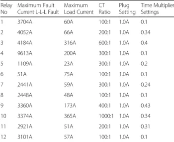
Table 2 represents various parameters calculated for formulation of objective function like maximum fault current, maximum load current, CT Ratio, Plug set-ting and Time multiplier setset-tings values for each relay (Additional file 1).
Referring to eq. (7) objective function of LPP can be stated as:
Minimize Z¼0:1X1þ0:34X2þ0:4X3þ0:1X4 þ0:2X5þ0:1X6þ0:24X7þ0:1X8 þ0:43X9þ0:34X10þ0:31X11þ0:1X12
Where X1, X2, X3, X4, X5, X6, X7, X8, X9, X10, X11, X12
are time multiplier settings for relays 1 to 12 Subject to constraints:
(1) 0.34X2–0.1X1≥0.5
(2) 0.4X3–0.34X2≥0.5
(3) 0.2X5–0.1X4≥0.5
(4) 0.24X7–0.1X6≥0.5
(5) 0.24X7–0.1 ×8≥0.5
(6) 0.34X10–0.43X9≥0.5
(7) 0.43X9–0.31X11≥0.5
(8) 0.31X11–0.1X12≥0.5
Extensive simulations are carried in MATLAB simu-link to obtain maximum fault current, maximum load current from simulated model of IEEE 13 bus distribu-tion test feeder. The maximum fault current is obtained by simulating L-L-L fault at each load. These values are required for calculating CT ratio, Plug setting and time multiplier settings for each relay.
6 Results
Keeping plug setting constant, the optimization problem becomes Linear Programming Problem. The LPP are generally solved by using MATLAB. Using dual simplex algorithm as a tool in MATLAB the optimum values are obtained for Time multiplier settings of the objective function.
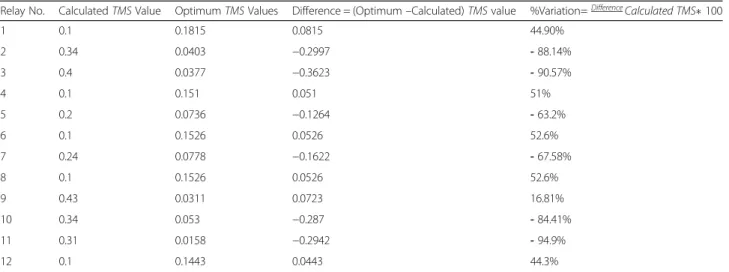
Table 3 represents calculated TMS values and optimumTMSvalues for each relay in test system.
In Table 3 above, Positive sign of column 4 indicates optimum value of TMS is greater than calculated value whereas the negative sign indicates optimum value of TMSis smaller than calculated value.
Positive sign of column 5 indicates % variation of dif-ference on positive side with respect to calculated TMS value where as negative sign indicates % variation on negative side with respect to calculatedTMSvalue.
Difference is calculated as:
Difference = (Optimum–Calculated)TMSvalue Difference is expressed as percentage variation of optimumTMSfrom calculatedTMS.
The results prominently shows effectiveness of Linear Programming optimization for designing an optimum protection scheme for radial distribution systems using directional overcurrent relays.
7 Conclusion
Results indicate that optimum Time Multiplier Settings vary in the range –94.9% to + 52.6%.The variations for all relays is shown in Table3.
The highest variation on negative side is observed for relay R11amounting–94.9%.
Relay R11 is provides primary protection for the load
connected at bus 692 if fault occurs at point (G) while it is provides back up protection for load connected at bus 675 if fault occurs at point (H) connected through underground cable.
Similarly highest variation on positive side is observed for relays R6and R8amounting 52.6%.
Relay R6 provides primary protection for load
con-nected at bus 611 if fault occurs at point (D). The relay R8 provides primary protection for load connected at
Table 2Calculated parameters for formulation of objective function
Relay No
Maximum Fault Current L-L-L Fault
Maximum Load Current
CT Ratio
Plug Setting
Time Multiplier Settings
1 3704A 60A 100:1 1.0A 0.1
2 4052A 66A 200:1 1.0A 0.34
3 4184A 316A 600:1 1.0A 0.4
4 9613A 200A 300:1 1.0A 0.1
5 1109A 23A 300:1 1.0A 0.2
6 51A 75A 100:1 1.0A 0.1
7 2441A 59A 300:1 1.0A 0.24
8 2448A 48A 100:1 1.0A 0.1
9 3360A 173A 400:1 1.0A 0.43
10 3374A 365A 1000:1 1.0A 0.34
11 2921A 51A 200:1 1.0A 0.31
bus 652 if fault occurs at point (E) connected through underground cable.
It is prominent that maximum variation in TMS is found when underground cable and over head lines are combined. The combined cable/overhead lines raise many issues on protection scheme due to high charging current and capacitance of underground cables. With increased capacitance the charging current also in-creases, which may be as high as significant fraction of the load current. This imposes limitations on minimum relays settings. Also high current transients are pro-duced due to energization and de-energization of cable circuit which are similar to fault currents of external protection zone of the underground cable. The protec-tion schemes should be able to cope with these transi-ent currtransi-ents, to ensure the reliability and security of protection scheme [9].
For these reasons, the protection schemes implemented for over head lines differs in principle than the protection systems implemented for underground cables [21]..
Hence it is concluded that Linear Programming optimization using dual simplex method provides an effi-cient tool for relay coordination problem in radial distri-bution systems using directional over current relays. With the use of optimized protection scheme, proper relay co-ordination can be achieved between primary and back up relays to avoid malfunctioning of relays which is needed to avoid unwanted outage of healthy part of the system.
8 Additional file
Additional file 1:Sample calculation for CT Ratio, Plug setting and TMS for Primary relay R1and backup relay R2for loads at bus 646 and 645.
(DOCX 13 kb)
Acknowledgements
Not Applicable.
Funding
No funding is received from any funding agency for this research work.
Availability of data and materials
The data for IEEE 13 bus test feeder is referred from standard test system published by IEEE POWER ENGINEERING SOCIETY, Distribution System Analysis Subcommittee, available publically on internet.
About the Authors
Mr. Sarang V Khond is Research Scholar pursuing his PhD in Electrical Engg. from Govt. Engineering College, Chandrapur (M.S.), India. Born on May 16, 1972, he graduated (1993) and post graduated (2010) in Electrical Engg. from Govt. College of Engineering Amravati. With more than 25 years of professional and academic experience, he is associated with HVP Mandal’s College of Engineering from last 16 years as Associate Professor in Electrical Engg. His areas of interest include Power system analysis, power system protection and artificial intelligence.
Dr. Gunwant A Dhomane is Professor in Dept of Electrical Engg., Govt. Engineering College, Chandrapur (M.S.), and India. He was born on April 9, 1963; He graduated in Electrical Engineering from Walchand College of Engineering. He completed his post graduation in Electrical Power Systems from Govt. Engineering College, Amravati in 1995. He has published 20 papers in national and international journals and conferences. He has completed his PhD from VNIT, Nagpur. His areas of interest include Power electronics, power system protection, and power systems.
Authors’contributions
SVK carried out problem formulation, simulation, calculations, preparing manuscript, GAD participated in problem conceptualization, coordination and helped to draft manuscript. Both authors read and approved the final manuscript.
Competing interests
The authors declare that they have no competing interests.
Received: 5 November 2018 Accepted: 3 April 2019
References
1. Paithankar, Y. G., & Bhide, S. R. (2007). Fundamentals of power system protection. New Delhi: Prentice Hall of India Private Limited.
2. Ram, B., & Vishwakarma, D. N. (2008). Power System Protection and Switchgear. New Delhi: Tata McGraw Hill Publishing Company Limited. 3. Mason, C. R. (1995)The art and science of protective relaying. New York:
Wiley.
4. So, C. W., & Lee, K. K. (2000). Overcurrent relay coordination by evolutionary programming.Electric Power System Research, 53(2), 83–90.
5. So C.W., Lee K. K., Lai K.T., and Fung Y. K. (1997), Application of genetic algorithm to overcurrent relay grading coordination, Fourth International Table 3Calculated and OptimumTMSValues
Relay No. CalculatedTMSValue OptimumTMSValues Difference = (Optimum–Calculated)TMSvalue %Variation=DifferenceCalculated TMS100
1 0.1 0.1815 0.0815 44.90%
2 0.34 0.0403 −0.2997 -88.14%
3 0.4 0.0377 −0.3623 -90.57%
4 0.1 0.151 0.051 51%
5 0.2 0.0736 −0.1264 -63.2%
6 0.1 0.1526 0.0526 52.6%
7 0.24 0.0778 −0.1622 -67.58%
8 0.1 0.1526 0.0526 52.6%
9 0.43 0.0311 0.0723 16.81%
10 0.34 0.053 −0.287 -84.41%
11 0.31 0.0158 −0.2942 -94.9%
Conference on Advances in Power System Control, Operation and Maintenance, APSCOM-97,Hong Kong,pp. 283–287.
6. Singh, M., Panighahi, B. K., & Abhyankar, A. R. (2013). Optimal coordination of directional overcurrent relays using teaching learning-based optimization (TLBO) algorithm.International Journal of Electrical power & Energy Systems, 50, 33–41.
7. Hussaina, M. H., Rahima, S. R. A., & Musirin, I. (2013). Optimal overcurrent relay coordination: A review, Procedia Engineering.SciVerse Science Direct, 53, 332–336.
8. Prashant P. Bedekar, Sudhir R. Bhide, and Vijay S. Kale(2009),Coordination of overcurrent relays in distribution system using linear programming technique, IEEE International coference on Control, Automation, Communication and Energy Conservation,pp1–4.
9. D. A. Tziouvaras, J. Needs (2014), Protection of mixed overhead and underground cable lines,12th International Conference on Developments in Power System Protection Copenhagen,Denmark,doi:https://doi.org/10.1049/ cp.2014.0132.
10. Zeienldin H., El-Saadany and Salama M.A. (2004), A novel problem formulation for directional overcurrent relay coordination,”IEEE International Conference,pp48–52.
11. Urdaneta, A. J., Ramon, N., & Jimenez, L. G. P. (1988). Optimal coordination of directional relays in interconnected power system.IEEE Transactions on Power Delivery, 3(3), 903–911.
12. Urdaneta, A. J., Restrepo, H., Marquez, S., & Sanchez, J. (1996). Coordination of directional relay timing using linear programming.IEEE Transactions on Power Delivery, 11(1), 122–129.
13. Chattopadhyay, B., Sachdev, M. S., & Sidhu, T. S. (1996). An online relay coordination algorithm for adaptive protection using linear programming technique.IEEE Trans on Power Delivery, 11(1), 165–173.
14. Abhyaneh, H. A., Al-Dabbagh, M., Karegar, H. K., Sadeghi, S. H. H., & Khan, R. A. J. (2003). A new optimal approach for coordination of directional over current relays in interconnected power system.IEEE Transactions on Power Delivery, 18(2), 430–435.
15. Meskin, M., Iyer, P., & Domijan, A. (2017). Impact of PV sources on the overcurrent relays in medium voltage distribution networks. In Nineth Annual IEEE Green Technologies Conference(Vol. 1, pp. 271–275).
16. Norshahrani, M., Mokhlis, H., Halim, A., Bakar, A., Jamian, J., & Sukumar, S. (2017). Progress on protection strategies to mitigate the impact of renewable distributed generation on distribution systems.Energies.https:// doi.org/10.3390/en10111864.
17. Sankara Iyer, P. (2009).Operations research. New Delhi: Tata McGraw Hill Publishing Company Limited.
18. Sharma, J. K. (2009).Operations research – Theory and applications. New Delhi: Macmillan India Limited.
19. Urdaneta, A. J., Perez, L. G., & Restrepo, H. (1997). Optimal coordination of directional overcurrent relays considering dynamic changes in the network topology.IEEE Transactions on Power Delivery, 12(4), 1458–1464.
20. Noghabi, A. S., Mashhadi, H. R., & Sadeh, J. (2010). Optimal coordination of directional overcurrent relays considering different network topologies using interval linear programming.IEEE Transactions on Power Delivery, 25, 1348–1354.