Getting the Most out of the Festool
Multifunction Table
by Jerry Work
Table of Contents:
• Introduction
• Set up - How the various components work together • Building the large MFT
• Squaring, clamping and work piece control
• Keeping your MFT surface free from glue squeeze • Making glued up flat panels the easy way
• The MFT is not “just” for for flat and square objects
• Mirroring - matching two sides of a cabinet simultaneously • Cutting to exact size
• Conclusion
Introduction
Recently I had a visitor to my studio and small gallery, a very accomplished furniture maker. After noting how Festool Multifunction Tables (MFT) and hand power tools had taken over most of my work
spaces, she asked what had been the most significant changes they had produced in how I work. I pondered the question for a while and then said there had been three really fundamental changes along with a bunch of smaller changes.
As we walked around we talked about how the first was occasioned by the tight integra-tion between the Festool Multi-function Tables and work posi-tioning accessories, the
Fes-tool Guide Rails and the FesFes-tool cutting Fes-tools like saws and routers. The guide rails and cutting tools allow me to machine furniture components by moving the cutting tool past a stationary work piece while in the past I always had to move the work piece past the stationary cutting tool. The MFT allows the stationary work piece to be held securely in a precise location, repeatedly.
Moving the cutting tool past a stationary work piece makes simple some common op-erations that can be quite challenging and error prone
when trying to move a work piece past the cutter. The ex-ample we talked about was how difficult it can be to ma-neuver the two sides of a cabinet carcass past a stationary cutting tool to make multiple blind sliding dovetail slots or dados in the two interior surfaces. Since you have to ref-erence all the cuts on one side from the top of the piece and on the other side from the bottom of the piece, it is very hard to get all of these slots to line up properly. Er-rors and ruined work pieces are not uncommon. When you reverse your thinking and instead hold the two cabinet sides securely together and move the cutting tool past these work pieces, you can cut as many sliding dovetail slots, dados or alignment marks as you need quickly, easily, and very accurately. It is a proc-ess I have come to call, “mirroring” since the two cabinet sides mirror one another perfectly. This is a major change for the better in how I work.
The second thing we talked about was doing panel glue ups. Like many furniture makers, neither of us uses man made materials very often, preferring the look, feel and fin-ish qualities of solid wood for everything from table tops to drawer bottoms, but, as the glue up either becomes quite wide or very thin, effecting the glue up becomes more diffi-cult. The outcomes are not always the best. Since the MFT allows wide, thin, thick or very long work pieces to be held securely both down flat on the table surface as well as tightly together, panel glue ups are now easy, fast and al-ways produce the desired outcome with little or no rework. This is another major change for the better in how I work. She smiled and agreed as she, too, often found thin or very
wide panel glue ups to be a challenge.
The third thing we talked about was squaring. Again, because the MFT allows you both to hold the work piece down securely against a flat surface and to easily clamp into a known square corner, everything from rail, stile and panel doors to drawers comes out perfectly flat and square each time. This is a major time saver and a “no-brainer” way to improve quality.
My visitor seemed highly interested when she left. A few days later she called all ex-cited to say she had placed her first order for a MFT and several of the tools and guide rails. As good as her work is now, I can’t wait to see how great it becomes in the future! In this manual I will share these and a number of other things I have discovered about how the Festool Multifunction Tables, the work positioning accessories, the guide rails and a number of Festool cutting tools might well change for the better how you work. First, though, let me say that I do not build art furniture. I like to think I could, but I don’t. Instead I build to a price point and I try to build furniture which my customers will view as a great value, a combination of the quality and the price, and which I will view as a good return on my investment and time. That means that I have to work efficiently to keep the prices in line and to a high standard to keep the quality up. I don’t give myself the luxury of spending days to get one curve or fit just perfect as one might doing art furniture or class projects. This quest for exceeding my customers’ value expectations moves me towards ever more efficient and less error prone ways to work. As we pro-gress through this manual I will be using first person singular terms a lot. This is not out of ego, simply my way of trying to convey what I have learned.
A lot has already been written about the use of the Festool Multifunction Tables and accessories in job site use and there is a growing body of writ-ings about using these components to replace contractor or cabinet style table saws. I won’t re-plow that ground here but will direct you to the Festool web site where you will find a number of excellent links covering both of these topics. In this manual I will try to concentrate on uses that are not quite as obvious and which I hope will help you to change for the better the way you build fur-niture in a shop or studio setting.
We will use real life examples as the pictures you see will all be of pieces built for clients. One ex-ample will be a small table that houses a flat panel TV and AV components. We will follow the
proc-ess of building this commission piece from start to finish. What this example piece will show is how you can use the Festool system to work differently, to work faster, and to a higher level of precision to produce a superior outcome in a shorter period of time. I hope you enjoy the read.
Set up - How the various
components all work
to-gether
For centuries a large workbench with heavy top, trestle legs, end and side vices, dog holes and built in drawers was the required first tool acquisition for aspir-ing woodworkers and furniture makers. They are optimized for holding work for hand cutting operations like hand planing or sawing. I must confess that I still build and sell such conventional workbenches and often find them inspiring pieces of furniture. It is just that I don’t use them myself anymore just as I seldom resort to hand tools any longer when high quality hand power tools can do a better job, faster.
A while back I purchased my first Festool Multifunction Table (MFT), a ruggedly built, folding leg unit with a field of evenly spaced 20mm holes across the top sur-face and “T” slots around the edges. It is a system optimized for holding work for hand power tool cutting operations like routing, sawing, planing and surfacing. I thought it would be a nice auxiliary table that would compliment my other tradi-tional work benches.
What I found is that it quickly replaced first one and then all of the large conven-tional work benches in my studio. It sim-ply was a superior way to hold work, and, with the many Festool accessories and guide rails, also a superior way to cut to exact size, to route multiple mirrored slid-ing dovetails to hold cabinet sides to-gether, to do all kinds of face and edge work, and much more.
Within a few months of the time this first Festool Multifunction Table came into my studio, I removed the last of the large tra-ditional workbenches and built an equally large (about four foot by nearly seven foot) Festool MFT from components read-ily available from the Festool catalog.
On top of that large Festool MFT this photo shows a number of the compo-nents we are going to employ throughout this manual. While the photo may look a bit intimidating, the pieces were all de-signed to work together logically, and you can buy the various bits and pieces only as you need them.
The Table
The MFT table itself comes very well packaged with sturdy folding legs and is available in two sizes. The MFT 800 is
23” x 28” while the MFT 1080 is 28” x 45”. The picture above shows the 1080 with all of its standard components. When you buy a 1080 you get far more than “just” the table itself. The picture below shows the MFT as it would normally be set up for a circular saw cut.
There are many ways you can set up the various components that come with the MFT and the additional components which you can purchase to make the
MFT even more functional for you. Don’t hesitate to experiment and try different configurations for different situations. Just because there is a “normal” or “stan-dard” way to use the components does not mean this is the only way to use them.
The Guide Rail
Each table comes packaged with one guide rail (shown at the front of the table left and two of them in the photo below) that integrates directly with all the Festool circular saws, routers and jig saws allow-ing you to move them in an exact straight line of cut. Unlike guide rails which merely form a straight edge for the tool to rest against, the Festool guide rails actu-ally hold the tool firmly to a “T” shape ex-truded into the guide rail itself shown in the photo below. The guide that is either built into or attached to each Festool rides on this “T” shaped section to hold the tool against both in thrust and out
thrust forces so the tool follows the guide rail exactly, rather than just bumping along one edge.
As we progress through the manual and see how to cut things like multiple match-ing slidmatch-ing dovetail joints or dados on both sides of a cabinet, you will really ap-preciate the importance of this guide rail system for far more than just cutting straight lines with a circular saw. The guide rail can be used by itself or fastened to two components which attach to the sides of the MFT to register the guide rail in the same location on the top
of the MFT time after time. The picture below shows the pivot component to which the guide rail attaches. In this photo the guide rail is just being inserted onto the gib of the pivot component. Once fully inserted, as in the photo to the right, the guide rail is secured by tighten-ing two screws.
Notice the factory supplied stop against which the pivot component rests (just
ahead of the black knob in this photo) so the pivot component can be removed and repositioned to the same place on the table time after time.
The photo at the top of the next column shows the guide rail properly in place and tightened to this pivot fixture. Note the lever clamp and sliding plate which allow the guide rail to be held at various heights off of the table surface, usually the thickness of the work piece so the guide rail rests on top of the work piece. The tool shown to the right of the guide rail is a handy accessory which can be purchased from Festool. It does not come standard with the MFT. It contains bits and drivers for all of the hex, slotted and star fasteners used throughout the Festool system. In this photo I had just
used it to secure the guide rail to the pivot fixture. I keep one in my apron pocket all the time.
The second component of the guide rail support system that comes standard with the MFT is the support fixture shown be-low that attaches to the opposite side of the table from the pivot fixture. This pic-ture is take from the bottom side so you can see the locating pin that fits into the underside of the guide rail “T” section to keep the guide rail from shifting side to side. You can see the height adjustment
cam clamp and plate and the factory supplied stop to keep this component properly aligned with the pivot fixture so when you remove and remount the guide
rail, it will be in the same spot time after time.
A nifty adjustable miter fence is also in-cluded along with a length stop that can be positioned anywhere along the miter fence. In the photo above the miter fence is being squared to the guide rail by the use of a large steel engineer’s square. The miter fence has an adjustable zero point so you can easily calibrate it to your table and guide rail support fixtures. At the near end of the miter fence is a lock down fixture which will hold the miter fence at the exact angle you select.
This photo is a close up showing how that lock down actually latches into a slot in the
side of the miter fence so it can’t move even when bumped.
All of the guide rails have two “T” slots built in. You can join two guide rails to-gether to make a longer one by the use of connectors (item number 482-107) as is shown below. The “T” slots also accept special clamps discussed a bit later on
that make it easy to hold a guide rail in exactly the right place on your work piece.
Also packaged with the MFT is an end deflector (item number 489-022) which prevents the power cord or dust collection hose from hang-ing up on the end of a guide rail.
The bottom edge of each guide rail has long soft rubber strips (shown on the next page on two guide rails that have been joined together) that do a great job of holding the guide rail in place even
with-out clamps. On the top side are green slick plastic strips that help tools glide with ease. Most unique of all is that each
guide rail features a hard rubber lip (top edge in this photo) that aligns zero clear-ance to the cut line of the Festool circular saws so you know exactly where the cut line will be. That hard rubber lip also minimizes tear out along the cut line.
Angle Unit
One guide rail accessory of note is the angle unit (item number 491-588). It is an extra cost acces-sory which does not come stan-dard with the MFT, but is very handy for a vari-ety of guide rail positioning tasks. It has metal pins and an adjustable gib to align one edge into one of the “T” slots on the guide rail. The other edge can be ad-justed to a precise angle. The compass scale reads from 0 to 90 degrees, but the unit will move through a full 180 degree range to allow you to directly transfer an odd angle to the guide rail and cut a piece that will exactly fit that angle. If you
wish, you can easily modify the angle unit to hold it fast to the guide rail by simply drilling a hole and inserting an 8mm bolt with the head in one of the T slots. Guide rails themselves come in several sizes from 32” in length to 197” in length and in two types. One type is a solid guide rail and the other comes predrilled for 32mm hole spacing applications. These predrilled guide rails come in ei-ther 42” or 95” lengths. There is a special fixture which attaches to a Festool router allowing you to precisely drill shelf
bracket, dowel or hinge location holes. More on that later.
The Legs
The MFT table legs are removable and fold up for ease of transport. One leg is adjustable to make it stand straight on uneven floors. There are rubber feet on the bottoms of the corner connectors which act like short legs when you want to put the MFT on top of something else.
“T” Slots
“T” slots run the full perimeter of the table both on the top edge of the heavy alumi-num side extrusions and on the outside edges. The “T” slots take a standard 8mm nut or bolt and will accept standard 1/4” sanitary T bolts or even square nuts so it is easy to make any kind of connec-tor you wish fit into these slots.
Special Clamps
Most all of the specially designed Festool clamps also fit into these “T” slots so you can quickly and easily affix a work piece to the sides of the MFT just as you might have done with the end and knee vice and side dogs on that conventional work-bench. Now with the MFT it is so much faster and easier to do.
Most clamps also fit into the field holes from the top or the bottom so you can quickly place them where you need them
to safely hold your work, a jig or fixture, or one of the Festool guide rails. In this photo the clamp is inserted from the top to hold the apron on this dining table tightly to the surface of the MFT. The special clamps come in several forms. Three are shown in the photo be-low. The screw type clamps come in two sizes: item number 489-570 (right) clamps up to 120mm and number 489-571 (left) clamps up to 300mm.
The Festool screw clamp design is like an “L” shape where the screw portion of the clamp tightens against a straight member. That straight member is sized to fit into the “T” track on both the MFT and the guide rails so the clamp stands upright on its own while in the track. If it is in the track on the bottom of the guide rail, it can’t fall out so no “third” hand is needed to set it in place or keep it in place.
What Festool calls a “quick clamp” (item number 491-594 in the center of the pic-ture below) has the same “L” form factor but instead of turning a screw handle to tighten, you only need to squeeze a han-dle to tighten. This is an easy maneuver with one hand. A quick pull on a release trigger releases the pressure and allows fast repositioning of the work piece and/or the clamp. These are nice units, and you simply cannot have too many of them. Festool offers other types of special clamps that can be most useful for spe-cial situations.
One of these (shown in use in the photo on the next page) is item
number 488-030 called “clamping elements”. They are for holding work pieces to the MFT table surface by exerting pressure on the
sides of the work piece. They have a head and foot component that mounts through the 20mm holes in the surface of the MFT and are held in place by threaded knobs which screw into the bottom of the 20mm mount-ing points after the clamps have been placed through the holes on the surface.
You can see a foot component with and without its holding knob at the lower right of the photo below.
These are low profile clamps sticking up only 20mm above the surface of the
ta-ble. So long as your work piece is thicker than that (or you elevate it with shims to be thicker than that), you can hold the work piece firmly while leaving the whole top surface free for sanding, routing, carving, drilling, etc.
They feature a smooth quick cam action that is ideal for repetitive holding of simi-larly shaped parts. Since the head and foot of each clamp can be set anywhere in the field of the MFT and you can de-ploy as many as you wish, you can hold oddly shaped work pieces with ease, something that is very difficult to do on a conventional work bench.
For holding irregularly shaped objects these clamping elements just can’t be beat.
Another specialty clamp is item number 489-790 called a “rapid clamp”. It is shown above the counter top ready to be inverted to draw the miter together in the photo below left and in detail in the photo directly below.
It is also a two piece clamp-ing unit. The head and foot both fit into “T” slots, usually on a guide rail (as in the fore-ground of the photo below). You can adjust the distance between the head and foot to be as long as you need up to the overall length of the guide rail(s) they are attached to. Once tightened down in the “T” track, a quick squeeze of a trigger exerts the clamping pressure. Not as much pres-sure as you get with either the “L” clamps or the “quick clamps” but handy when you need to clamp a guide rail to an irregular surface like the closed sides of a box or chest where there is no lip for the “L” style clamps to establish pur-chase.
If you want to use these rapid clamps on their own without a guide rail (like in the photo of the mitered kitchen counter top),
Festool sells what are called “clamping profiles” (item number 490-189 is 800mm long and number 490-190 is 1400mm long). These are sturdy aluminum extru-sions with four “T” tracks into which the rapid clamp head and foot pieces can be affixed to make a stand alone clamp (shown in the background in the photo below).
Stops
Festool supplies three kinds of stops to hold a work piece at a known distance away from the edge of the MFT, or the edge of a guide rail, or to stop a tool at a known spot along a guide rail.
Item number 488-564 functions a bit like a one ended clamp. It is called a “longi-tudinal stop”. It sits in the “T” track around the top of the table and has an adjustable arm that can be set a precise distance from the edge of the table. This allows you to butt a work piece against the end of that arm to precisely place dif-ferent work pieces in the same place for performing the same operation on multi-ple same sized parts. The arm is on a pivot so it can be raised up out of the way of your machining operation if you so de-sire. A very handy gizmo. You will find numerous uses for this one as we pro-gress through this manual.
Another adjustable stop is item number 490-555 which clamps onto the miter fence to position work a known distance away from the guide rail. Its companion is called a “limit stop” (item number 485-827), and it fits on the guide rail itself to limit tool movement to within a precise location. You will want at least a couple of each of these as they greatly simplify and speed up set ups.
Table Extension
The final direct MFT accessory we need to mention is the table extension (item number 489-575) shown below holding the edge of a long board that would ex-tend off the edge of even this very large MFT. It is an extra cost item that does not come standard with the MFT but adds greatly to its functionality.
This extension is an extruded aluminum deck 10.75” x 27.75” which affixes to any edge of a MFT. You place these on the ends to make the table effectively longer or on the sides to make it effectively wider.
With these many very handy accessories, let’s see how to get the most from the Festool MFT in a fixed studio or work shop setting.
Because the Festool MFT can be folded up for ease of transport, it is easy to see how handy these would be for working off
site, say in a customer’s home. However, I find them even more valuable sitting in one spot in my work area day after day, and that is the use we will focus on in this manual.
Building a large MFT from
readily available catalog
components
Before we launch off into all the many uses to which you will put your MFT on a daily basis, let’s take a few moments to talk about how to build larger MFT tables than the two sizes supplied by Festool. My studio life changed dramatically when I built my first large MFT. Suddenly I found myself doing things I just hadn’t been able to do easily before. Take a look at the pictures that follow as just two examples.
The first shows a dining room table made from Peruvian Walnut being assembled upside down on the large MFT. That ta-ble was over 4’ wide and over 10’ long when open. With that much span the structural requirements on the sliding mechanism were significant. Yet, with a solid walnut top that long (cross grain construction so most all of the seasonal movement was along the length of the table) the sliding mechanism had to ac-commodate a lot of wood movement as well as a lot of span weight.
A number of dovetailed cross pieces were needed to reinforce the sliding
mecha-nism. To make sure that as-sembly went together straight and true required a perfectly flat work surface large enough and strong enough to keep everything aligned. The large MFT was just the ticket. At 4’ wide and nearly 7’ long plus that nifty table extension add-ing more than another 2’ in length, every-thing came out right on the button.
The second set of photos shows assem-bly of a book case over 9’ long by 7’ high made from Australian Silky Oak and Ore-gon Black Oak. To get it into the client’s home, it had to be build so the top could be removed from
the base.
In this photo one side of the unit is held to the side of the large MFT with the legs supported by fir blocks
shimmed to be dead flat.
The aesthetics depended on the uprights appearing to be solid pieces 7’ high. The answer was to split each upright and re-join them on site with a sliding dovetail joint, a dovetail key and a loose tenon to keep all the edges aligned properly,
mak-To join the tables side to side like this you will need to remove the factory side stops that are used to position the guide rail holding fixtures. With four sets of legs supporting the work surface, this large MFT will hold all the weight you could lift onto it.
The picture above shows these same two 1080 MFTs joined together end to end to form a really long work surface. For size reference that is a nearly 8 foot long guide rail on the top. To fit two 1080 MFTs together end to end you need to fold up one set of legs as shown. With three sets of legs on the ground this work surface is also very sturdy and can take all the weight you would want to put on it.
The table joining ele-ments are similar to the guide rail joining ele-ments dis-cussed ear-lier but thicker to fit the “T” slots around the perimeter of the MFTs. In
the photo below left you can see two ta-ble joining elements in the foreground and two guide rail joining elements in the background. The close up photo below shows the difference in thickness
be-tween guide rail joining units (center) and table joining units (outside).
Another way to build a larger MFT
You can also build larger MFTs using dif-ferent catalog components. The three top plate MFT shown below and in many
of the photos in this manual I built by or-dering one 1080 MFT (item number 492-652), one pair of two meter side rails - called “table profile” in the catalog (item number 488-555), and two additional top plates called “perforated plates” in the catalog (item number 489-396).
I disassembled the MFT 1080. The side rails of the MFT 1080 became the end rails on this large table. The two meter table profile extrusions became the side rails and fit perfectly into the cast corner brackets of the MFT 1080. Since the per-forated top plates are 725mm wide, three of them are longer than the 2 meter side rails. You have two choices. The one I elected was to cut down one of the top plates so the three would exactly fit in-side the in-side and end extrusions. The other option would be to cut off pieces from the end rails on the MFT 1080 and use them to extend the two meter table profile extrusions to just fit the overall length of three top plates side to side (2175mm).
I’m not sure it makes much difference, but I thought the two piece side rails
might be weaker than the one piece units. It turns out the off cut piece of the third top plate makes a very handy straight edge with the same 20mm holes in it so it is a very usable jig on its own.
To keep the top plates aligned with one another, vital to maintaining the flat work surface shown, I suggest cutting biscuit slots or a spline slot in each mating edge. Don’t glue the biscuits or splines in place and don’t glue the edges of the top plates either. You want to be able to easily replace a plate if it becomes damaged. The biscuits will swell up on their own just from the moisture in your shop so will hold quite firmly with-out any glue yet they can be re-moved later if necessary.
The only other thing you will need is a sturdy set of legs and some cross string-ers that will sit under the table to reinforce where the plates join. As much as I like the sturdy Festool MFT legs, they are sized to fit on the ends of a 1080 MFT so
are not wide enough to fit on the sides of a 1080 MFT which are now the ends on this three plate MFT.
I used a set of cast iron legs sourced out of Canada separated by fir stringers all held together with threaded tension rods. This makes a very sturdy leg assembly for this three top plate MFT which can be tightened if it ever begins to rack from day-in day-out use. Mine never has loosened and certainly does not rack so this set up has been ideal. You could also build a set of legs from any hard wood or from vertical grain clear fir or could modify the Festool leg set if you wished.
I wanted this MFT to be higher than the Festool 1080 so I added a stringer on top of the legs that runs full length side to side. I used oak 60mm wide by 40mm deep, pocket hole screwed these into the top plates from below, and screwed them to the top of the cast iron leg set. Holding the top plates 40mm above the top of the cast iron legs made the overall table height just match the height of the table surfaces on the European combination machine that sits near this large Festool MFT. It is a comfortable working height for me but adjust your working height to be optimum for you and your shop or stu-dio layout.
The final assembly detail is to place stringers across the table under the joints between each top plate. I used oak 20mm wide by 40mm deep pocket hole screwed into the bottom of the two adjoin-ing top plates. This yields a work surface that has remained dead flat.
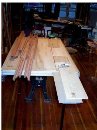
In addition to all the work piece holding features and guide rail uses we will ex-plore next, this work surface is also very handy for
mundane things like set-ting out stock to select grain be-fore ma-chining as is shown in this pic-ture.
Squaring, clamping and
work piece control
When first considering a Festool MFT, most people seem to be drawn to the guide rail aspect of this system. As we will see shortly, that is an important fea-ture, but the most common thing you will do day in and day out is hold work pieces in proper alignment while you work on or assemble them. And, I find the most common kind of alignment is squaring. No matter what kind
of furniture you build, most likely some aspects of your piece will need to be assembled to be exactly square. If they are, your final piece will go to-gether correctly, will sit flat on the floor, look good, and func-tion the way you in-tended. If it is not square, the rest of the assembly can be a nightmare, and the finished piece rarely exhibits the quality you want. So while the act of squaring sounds simple, following the conventional
prac-tice of measuring diagonals and readjust-ing clamps, it is not.
Here is a quick, simple and fool proof way to achieve nearly perfect square assem-blies every time.
Create a corner that is known square and clamp your assembly into that corner as is shown in the photo below. Position your clamps over the outside edge of the known square and over the opposite out-side edge of your assembly. As you draw the clamps tight the assembly is drawn into the known square corner so it will also be square without any fiddling or measuring.
Since this is such a common operation in furniture making, a squaring jig is one of the first things I suggest a new Festool MFT owner make for personal use. It can
be made from any pieces of scrap, but, since you will be us-ing it so often, I suggest you take a little time to make a nice squaring jig that you will enjoy using which exhibits a bit of the quality you want exempli-fied in your work. I made one leg from oak and one leg from walnut each 46mm wide by 26mm thick by 1210mm long. To make sure they never warp or twist and stay straight I suggest laminating two or more pieces together. Laminated wood remains far more stable than a sin-gle solid piece ever will. In my case I used two pieces 14mm thick and around 50mm wide. Once the glue fully cured, I machined the pieces to the final dimen-sions and used a 45 degree bevel cutter
mounted in a router to break the sharp edges.
You want to be able to locate your squar-ing jig anywhere on the surface of the Festool MFT or on any side or end. It would be easy if 20mm dowel that would fit into the 20mm holes in the top surface of the MFT was readily available. It is not in most places. However, at nearly any hardware store you will find .5”
female con-nectors de-signed for holding two pieces of .5” threaded rod
to-gether. It turns out these are almost exactly 20mm across the points so they fit the 20mm holes well and re-peatedly.
Epoxy one in one end of each arm of your squaring jig. Place it centered about
50mm from one end and 15mm from one edge. Allow it to stick out about 18mm from one face. That will make it recessed slightly on the other face if your compo-nents are the size I used.
When you want to use this arm anywhere in the field of the MFT, just plop the pro-jecting connector into one of the 20mm holes and screw in a 1/2” bolt with
washer from the underside of the table to secure it in place. To make it even hand-ier, epoxy a nut run up against the head of a 1/2” bolt and epoxy on a washer like the one
shown next to the
wrench in the photo below left. Now the head of
the bolt and the nut make for an easy hand hold and the fixed washer allows one handed fastening.
To make it easy to mount one of these arms into the “T” slots on the top of the outside extrusions on the Festool MFT, drill several 8mm holes centered on 20mm in from one edge. In the pictures these are drilled in the oak arm.
Place 8mm bolts into these holes with the heads protrud-ing down on the face oppo-site the face that has the 1/2” connector sticking out. These 8mm bolts will slide right into the “T” track and can be quickly tightened in
place. The 20mm edge to center line spacing of these hold down bolts will keep the edge of your squaring arm par-allel with the top plate on the MFT which will provide extreme clamping strength without deflection.
Use 1/4” toilet flange bolts if you prefer them to 8mm. They will function just as well.
For the walnut arm insert the connector into one of the corner-most holes in the Festool MFT. Mark and drill an 8mm (or 1/4”) hole centered over the “T” slot on the opposite side of the MFT.
In use the 1/2” connector with a bolt se-curing it from the bottom and an 8mm bolt with its head in the “T” slot on the other side of the table will hold that arm very securely as shown in the photo below right.
Now you have two arms almost 4’ long which can be adjusted at nearly any an-gle relative to each other. The most common configuration for me is to put the first arm into the “T” slots on one long side of the Festool MFT secured with nuts and washers from above and the second arm into the corner most hole in the top plate of the MFT secured from be-low with the 1/2” bolt/nut/washer combi-nation on one end and the bolt in the “T” slot on the other side of the table.
I use a large steel engineer’s square 250mm by 500mm by 10mm thick to cre-ate a perfectly square corner between these two arms. It only takes a minute to set up and the corner is known square. No matter what I want square, I can clamp it into that corner and know that when the glue dries the assembly will come out dead on square without any
measuring or secondary operations. It also will be flat because it can be held flat on top of the MFT top surface. Those 20mm holes and the nifty “L” shaped Fes-tool clamps make it easy to clamp the as-sembly down to the table while you are drawing it into the known square corner. I use this set up for all kinds of things. Rail, stile and panel doors are a cinch to get right. So are drawers, boxes, frames, cabinet carcasses and just about any-thing else you can think of that needs to come out square and flat.
Even flat mitered corners that normally squirm all over the place are easy to do. Just place one corner into your known square and place the large steel square over the opposite corner. Put two clamps going each way across your mitered piece. One end of the clamp goes over the outside of your squaring jig and the other goes over the outside of the steel
square. Festool “L” clamps hold every-thing down flat against the top of the MFT. As you begin to tighten the clamps, the miters can easily be aligned to come out properly flush and perfectly square. Believe me, this is vastly easier than try-ing to do this with traditional corner clamps, band clamps or bar clamps! If you don’t have a large steel square, simply use your known square corner to make a square of whatever size you wish out of whatever wood you have on hand. Reinforce the joint with a steel plate or
hunk of baltic birch plywood, a few screws and some epoxy, and it will stay square for years to come. Don’t use normal yellow or white wood glues as those tend to creep and might allow your square to become something else.
The key is that you are clamping your as-sembly into a known square corner and, if you wish, with a known square on the opposite corner. Keep the assembly from twisting by tightening the Festool “L” shaped clamps to hold it tightly to the flat top surface of the MFT.
This simple set up will save you hours of time and frustration on every project you do in the future. If you are like I am, you will likely say to yourself that you can jus-tify the cost of the whole MFT set up with this one operation alone.
You could do something very similar with any flat work surface, just not as easily or as quickly or as repeatedly.
Best of all, your squaring arms can be used on a single MFT, or two or more MFTs joined together with the
“verbind-ers” or on a three plate MFT with equal ease. You can use them along the edges as shown here or anywhere in the center of the MFT as we will see in subsequent chapters.
One particularly nice appli-cation is to set up a known square with the apex aligned to the guide rail and each arm projecting out 45 de-grees from the guide rail. Now you can cut perfect mi-ters even if the guide rail is not set exactly 45 degrees to the two arms. Since the arms are 90 degrees to one another, if you cut the right miter against the right fence and the left miter against the left fence, the resulting joint will be exactly 90 degrees.
If you are cutting molding or other trim, the corner you are fitting into often will not be exactly 90 degrees. No problem. Just set the squaring arms to whatever that angle is, cut the right side against the right squaring arm and the left side against the left arm and the trim will fit perfectly every time.
Keeping your MFT table
top surface and squaring
arms free of glue squeeze
I often laugh when I ask first timers to my studio what they think the most danger-ous tool in the place is. They invariably point to the big cutting tools like the shaper and table saw. They are sur-prised when I disagree with them and hold up instead a measuring tape with the comment that more accidents are made with a measuring tape than with any of those other tools.
I usually follow this question with another, “what is the most useful tool in the
place?” They generally ponder a bit knowing the first question had turned out to be tricky. This answer is a roll of white butcher paper mounted on my old fash-ioned (somewhat cluttered) sales counter, the one pictured here.
Every time I want to glue something to-gether, I rip off a piece of the butcher pa-per and place it on top of the MFT sur-face. The paper is less than 0.1mm thick (around .003”) so it doesn’t throw the as-sembly out of whack, but it sure does help to keep the MFT surface and the squaring arms clean. Butcher paper is hard enough to prevent the glue from bleeding through and yet absorbent enough to soak up some of the excess. The paper that gets glued to the work pieces comes off easily with the first sanding.
Here is a sequence of photos to show how handy this can be. I tuck the paper under the squaring arms so it won’t be in the way.
Next the individual components get laid out for a final look be-fore glue up.
Clamp into the square corner and down flat on the sur-face of the MFT so
you know your as-sembly will come out flat and square every time with no glue mess on your MFT.
Making glued up flat
panels the easy way
Many furniture projects require glued up panels. They may be used for tops, the panels in rail, style and panel doors, cabinet sides, dust shields between drawers, drawer bottoms or simply to get wide enough carcass pieces for the de-sign you are building.
Traditional “wisdom” says to joint the edges of two or more boards, plane them to all be exactly the same thickness, align them with biscuits or splines, clamp them together with clamps alternating over and under the panel and then hold the whole mess flat with cull boards clamped across the panel between each edge to edge clamp.
The problem is that that rarely works very well or very easily. If you cut your biscuit or spline slots exactly the same distance from all the top edges and perfectly paral-lel with the top edges, the boards will likely align correctly, but the panel often will take on a bow just because some clamps are drawn more tightly than oth-ers. Or, if your cull boards don’t have just the right amount of center down bow, they may not hold the panel flat side to side.
With the Festool MFT you can make child’s play out of this once frustrating process, and you can do so even if your boards are of differing thicknesses or if you don’t want to take the time or have the ability to cut biscuit or spline slots ac-curately.
The key is to clamp all your work pieces down to the surface of the Festool MFT
while you are drawing them together with the side to side clamps. Being forced to a flat surface to begin with means that as the glue dries there is no tendency to warp or pull away from that flat surface so the panel comes out flat once the glue dries. If the boards are of different thick-nesses, it won’t matter because you are clamping what will be the top surface of all of the boards to the same flat surface so those edges will all align properly. I try to always take the time to properly prep my stock by jointing one face and one edge and then planing the other face and edge to be square, straight and par-allel. While this adds a little time, it in-sures a proper outcome. We will talk a bit later about how to cut the edges to be “glue line straight” using the Festool guide rails and a Festool circular saw if you don’t have a jointer or one of the right
size for the sizes of work pieces you are using for your panel glue up.
I also always take the time to cut biscuit slots aligned from what will become the
top of the finished panel. By placing the fence of the biscuit joiner on the top of the work piece, I have good confidence that each biscuit slot will be very close to the same distance down from that face. Just make sure your biscuit joiner has a
fence that is really parallel with the cutter. Unfortunately, many are not.
A good trick is to use one of the squaring arms you built earlier to act as a stop for
the work piece so you don’t have to rely only on down force to hold it in place as is shown in the photo above.
Another thing to keep in mind is that the surface of the MFT stands proud of the aluminum side and end extrusions. This
space is very handy for cutting biscuits in thinner stock as shown here.
Once the stock is prepped and the biscuit
slots cut, I tear off pieces of the white butcher paper to cover the MFT surface where the glue lines will be.
My technique is to apply glue first into the biscuit slots, then to both edges with a small paint brush. Next I insert the bis-cuits alternating piece to piece. The process of inserting the biscuit will nor-mally force out some glue and I use the paint brush to apply that glue to the pro-truding edge of the biscuit. Once the
pieces are aligned, I use a rubber dead hammer to bang them to-gether and place the panel with what will be its top sur-face down on
the surface of the MFT.
I start with a bar clamp in roughly the middle of the panel. Before I draw it to-gether, I use a Festool “L” clamp to hold the outside edges of the panel down flat on the MFT surface. Then I draw the clamp up tightly. I repeat this process proceeding from the middle out with a bar clamp about every 12 inches or so. In most cases the combination of the bis-cuits holding the faces in proper align-ment, the joined edges mating at a true 90 degrees to the top of the MFT, and the Festool “L” clamps preventing the out-board edges of the glued up panel from lifting under the clamping force causes the glued up panel to lie perfectly flat and dry without clamp induced stress.
On rare occasions when the stock is not properly prepped, the middle of the glue up may try to bow up. If this happens, just set a block down where it is trying to bow and use any old cull board and two more Festool “L” clamps outboard of the panel to force it down tightly to the MFT surface.
The glue that squeezes out between the MFT and the panel is captured by the white butcher paper. The glue that squeezes out on the side facing you can be wiped off with a paper towel or you can leave it until it becomes a bit plastic and cut it off with a chisel or plane once the bar clamps are removed.
Since I started doing this shortly after purchasing my first Festool MFT, I can’t remember a glued up panel that didn’t come out just right no matter how big. One picture on the next page shows part of a set of kitchen counter tops made from White Oak. Single pieces were over
2 feet wide and over 10 feet long. It was a heavy monster and I really appreciated the large MFT for that job!
The glue up shown here is half of that unit. After both halves were done, I put them together the same way.
The bulk of this glue up was held down flat on the top surface of the large MFT. One projected end (about two feet long) was held flat by the Festool table exten-sions set flush with the top of the MFT and the other (about a foot long) by a sandwich of 3/4” plywood culls. Even that large piece came out straight, flat and properly aligned. It took less than a .5mm pass (less than .020”) on the wide belt sander to get everything perfectly flat and ready for final sanding and finish. In the past when I have been faced with large panel glue ups of this size, it was a real crap shoot as to how they would
come out. Now I don’t even think about it any more, it is so easy and repeatable.
Also, there is no reason to do just one at a time. Fill the table with as many as it will hold to save your time. The large three plate MFT is shown above and the
This same process works just as well for small or thin panels as for large thick ones. I really like the look of book
matched solid wood drawer bottoms and now find it easy to glue them up even for large drawers. Since a “standard” biscuit slot is 4mm thick and you need at least 2mm of wood on either side of the biscuit, you need to plan on drawer bottoms that are more than 8mm thick if you biscuit the edges. Since a drawer bottom is held all around its perimeter anyway, I find that I can simply edge glue panels down to 6mm thick for smaller drawers with little chance of failure.
The picture to the right shows a simple looking but challenging glue up. It is mul-tiple short boards glued to make a cross grain rather than long grain panel. Using the “conventional” one clamp up/ one clamp down process, multiple short boards like this will nearly always bow and twist. Doing it with the MFT, the glue up came out flat and straight - just as I expected.
The MFT is not “just” for
square and flat objects
So far we have talked mostly about how to use the MFT to make and hold square and flat objects. It works just as well for curved and three dimensional construc-tions as well.
One example is using the MFT and one of the squaring arms you built earlier as a handy straight reference for oddly shaped pieces. The pictures show various steps in making a large gong stand from Brazil-ian Cherry, South African Blood Wood and Oregon Black Walnut. This unit holds a symphonic gong 36” in diameter that is quite heavy so the stand needed to be adequately strong.
The strength and vibratory requirements dictated that the trestle be made from two pieces joined together in only two places by a short stretcher with sliding dovetail joints (shown in this picture made from
blood wood) out towards each end. For portabil-ity the tres-tle top had to be re-movable from the side up-rights but the joint not readily discernible, as shown in the photo below.
For strength two dowels were required in the top of each upright to mate with each side of the trestle.
This was all made far more complicated by the fact that the trestle was curved on both the bottom and top faces with vary-ing radius curves.
So, how in the world can you cut the four female sliding dovetail slots to exactly align both pieces of the trestle one with another while
at the same time keeping the joint lo-cating dowels properly aligned with the holes in the bottom of the trestle feet?
One very laborious way would be to build a template jig, cut the dovetail slots and drill the dowel holes before cutting the curved top and bottom surfaces of each
side of the trestle. Given the sizes of the pieces, I found it far less labor intensive to cut the curved shapes first and do the
alignment for cutting the dovetail slots on the MFT with a Festool guide rail and router. That is where the squaring arm comes into play.
I set the Festool guide rail into the included holder which fastens into the “T” slots on the side of the MFT. The squaring arm was then set to be 90 degrees to the guide rail. One trestle piece was placed with the bottoms of its mounting feet against the squar-ing arm and its inside face point-ing up, away from the MFT sur-face. A second cull board was clamped with Festool “L” clamps to hold its face to the two points on its up-curved top edge. The squaring arm was then removed.
Once in place the trestle could be moved up and down this cull board knowing that the flats on its mounting feet would
al-ways be 90 degrees to the guide rail even though the curved top edge might not be exactly symmetrical side to side.
Next, dowel pieces were inserted into mounting holes and the second piece registered to the first with its inside face also pointing up away from the surface of the MFT. The two pieces of the trestle could then be moved to properly locate the router to cut the sliding dovetail re-cesses in both pieces at the same time. It is easy to
align the router to the intended line of cut using the mark on the front of the router base as shown.
As a result, even though the two sides of
the trestle were not necessarily the exact same shape and the two halves of either side were not necessarily exactly
sym-metrical, the dovetail slots cut in each kept them and the dowel holes perfectly aligned, something that would not be easy to do in any other way that I know.
Once you start using the Festool MFT as your primary multi pur-pose jig like this, all kinds of ap-plications will become apparent to you. Every day I have another “aha!”.
Here is another example, this time plac-ing four Lamello biscuit style brass hplac-inges into two doors for a rail, stile and panel chest held together by sliding dovetails. The key is getting the doors and the sides properly aligned and held stable while you make the plunge mortise cuts for the hinges.
I used the Festool “L” clamps to hold one side to the side of the large MFT standing proud from the surface by the width of the
doors. The dovetailed dividers were inserted into this side and then into the other side standing up-right on the surface of the MFT.
Now both doors could be located in the opening in which they will live using washers all around to maintain the proper spacing. A pencil mark located the hinges and they were easy to plunge cut from this orienta-tion. I really like these hinges, but they can be a challenge to align any other way.
Another example is building a hall table with top shelves made from steamed eucalyptus
and legs and lower shelf from highly fig-ured Ore-gon Big Leaf Ma-ple. The key here was gluing the
stretcher dowels with the
legs perfectly square so they would stand without wobble.
Using the MFT, Festool clamps, and the squaring arms built earlier, this was easily achievable. Two square corners were
established on the MFT surface. Each leg assembly was clamped into these known square corners. The Festool clamps held the legs firmly against the surface of the MFT so nothing could move as the glue dried.
From these few examples it is apparent that the Festool MFT provides three di-mensional work piece positioning that is not at all obvious when you first look at “a table surface full of holes,” as first time viewers often describe the MFT.
Though that first impression is apt, there is so much more than that to a Festool MFT. The holes are quite accurately po-sitioned across the whole field so you can reference from anywhere with a simple-to-make squaring arm. The variety of Festool clamps can be positioned with the clamping element on either the top or the bottom surface and anywhere across the field so you can securely hold objects of nearly any shape. The “T” slots on the
upper, lower and side surfaces of the ex-truded table sides can help support work in upright and overhanging positions.
The table surface can be ex-tended to be wider and longer to match your work piece holding requirements. And, very importantly, a Fes-tool guide rail can be set at any angle relative to your work piece and can be used to guide a circular saw, a router or a jig saw in an ex-actly straight line and at a known distance away from the surface of the MFT. Fi-nally, with Festool table join-ing elements you can easily put together as many Festool MFTs as you need for the size of your work pieces. Now let’s explore more about those Fes-tool guide rails and how they can alter for the better how we work.
Mirroring -
Cut-ting the two
in-terior walls of a
cabinet carcass
to be exactly the
same
As was discussed a bit in the introduc-tion, one of the most important changes in how I build fine furniture occasioned by my use of the MFT is the ability to easily and quickly cut a series of dados, sliding dovetail slots, or component positioning lines in two or more work pieces at the same time.
The most com-mon thing you will use this for is cut-ting these slots in the two interior sides of a cabinet carcass to hold shelves or drawer guides. You will also use this for cutting such slots to hold upright components like interior walls or even to hold the
sides of the carcass to the top and bot-tom of the cabinet. In fact, shortly after you start using the techniques we will cover in this chapter, I predict you will change for the better how you build all case goods in the future.
While there is a bit of a learning curve to visualizing in three dimensions, within a short time you will regularly be doing such mirroring in all three dimensions: side to side, front to back, and bottom to top.
It makes no difference whether you build your cabinet carcass from solid material, man made material or built up rail, stile and panel components. Once the com-ponents are nice and square, you will do the mirroring cuts the same way.
While it is possible to make the cuts de-scribed here by a number of other
means, I have yet to find any system that is as fast, reliable, accurate, and repeat-able as is made possible using the Fes-tool MFT, guide rails, and router.
First, the MFT provides a flat surface and an easy way to hold your work pieces stable while making the cuts. Second, since the Festool guide rail holds the
router in a straight line whether cut-ting with or against the rota-tion of the bit, you can cut in either direction accu-rately. Third, since you can hold the two sides of the work pieces together through the whole cut se-quence, all the slots and marks will be in exactly the same place on both pieces no matter how many slots you need to cut. Finally, the ability to control the depth of cut with Festool routers with great accuracy makes possible multiple interlocking
slid-ing dovetail joints that you might never have imagined before.
You need to start with components that are flat and square. We covered how to square most anything and how to make flat glue up panels in earlier chapters. Now let’s combine these with mirroring. As an illustration of the techniques, we will follow along the construction of a real project for one of my clients. They
wanted a small cabinet to house a flat panel TV, their audio video components on adjustable shelves behind a door, and some small speakers on either side of the door. The more traditional armoire style piece which completely hides the TV when closed would have been too big and domi-nant visually for their space and style. The room where this piece will live is done in an arts and crafts
style with two wonderful Morris chairs, a period leather couch, and other furniture pieces I have built for them from Oregon black oak and Australian silky oak (often called “lace wood” in North America). This piece was to be made from the same wood combination with the TV sit-ting on top, a flapper door rather than
swinging doors to hide the AV compo-nents, an open back for cooling and ease of cabling, and room on each side for the two small speakers. To fit the intended space it had to be no more than about 32” wide by 17” deep and 22” high. To fit the arts and crafts theme, a rail, style and panel construction was se-lected. The top was to be a single glued up piece of black oak. The bottom was to employ rail, stile and panel construction and be made from black oak. The out-side out-sides which also would form the legs were to be rail, stile and slat components made from the silky oak. Inboard would be two rail, stile and panel uprights made from black oak and drilled for adjustable
shelves which are made from glued up panels of black oak. The flapper door was to have silky oak rails and stiles with black oak panels. The front toe kick was to be silky oak. Since there would be no back, it was important to make sure the structure itself would provide plenty of rack resistance so the flapper door would work properly.
The outsides slide into sliding dovetail slots in the underside of the top. The bot-tom slides into sliding dovetail slots cut on the inner faces of the outside
compo-nents. The inner uprights slide into slid-ing dovetail slots on the underside of the top and on the upper surface of the bot-tom rail, stile and panel component. The
flapper door utilizes brass pins sliding in dados cut on the inside faces of the inner uprights and is supported at the front of the unit when in the open position by two more brass pins.
All the sliding dovetail slots were to be stopped from the front so they would not show.
So, here is a piece that has solid wood components, rail, stile and panel com-ponents, both dovetail and dado slots which run side to side, bottom to top and front to back. They are all
stopped so they don’t show from the front. And, it all has to go together rig-idly with no back to add lateral sup-port.
This ought to be enough of a test to see if squaring, panel construction and mirroring using the Festool MFT
can alter how you build just as it has altered how I build.
To let the secret out early, I built this piece start to finish in less
than one third the time I used to take making similar pieces. Therefore, I could sell a better quality piece less expensively. Also, the perceived value for my cus-tomer was much greater than it would have been had I followed past practice. Faster build time for me and a more precisely crafted piece add up to better value for my customer and a greater profit margin for me. That is what I call a good re-turn on investment in tools, in this case the Festool MFT, guide rails, and router.
Once the individual pieces were cut, all of the component assembly, squaring and mirroring cuts were done exclusively on the MFTs using a Festool guide rail and router.
I work to a set of standards based around the metric system of measurements as it is far faster and less error prone for me to do so. In this case the piece is built to what I call a 50mm by 20mm by 10mm standard. That means that all the rails and stiles are 50mm wide by 20mm thick with 10mm wide and deep mortise and tenon joints. With modern glues these standards provide plenty of gluing surface for a strong assembly. All the dovetails are 10mm deep cut with a 20mm dovetail cutter. I like angles around 15 degrees so use the Festool router bit of these specs to make the cuts.
The math is quite simple. All I need to know is the overall outside dimensions of the piece in order to calculate the size of each assembly. Once the size of the as-sembly is known, then sizing the individ-ual components is a snap.
For example, the top on this piece is 820mm long and overhangs the sides by 20mm. Since the sides are 20mm thick, then the center lines of the dovetail grooves which will hold the sides to the top are 30mm in from each side and 760mm apart. The interior space be-tween the inside uprights is 490mm so these two dovetail slots are 510mm cen-ter line to cencen-ter line. Hence the cencen-ter line spacing from the outer dovetail slots to each of the interior dovetail slots is 125mm. And so on.
Let’s start with the glue ups for the top and the various pan-els. As discussed in that chapter, making glue up panels is easy, fast and nearly fool proof using the MFT. Cut the individ-ual boards to width and thickness, biscuit and clamp them to-gether face down on top of a piece of pa-per on the MFT. Use Festool clamps to hold everything down flat on the surface of the MFT and draw the assembly together with bar clamps. Once the panels are glued up, they are cut
to final dimension and sanded flat using
up through 400 grit. In this case I used a small wide belt sander to flatten, but you could easily use the Festool Rotex or the linear sander as well.
The rail and style components are all cut to overall size and then the corners are broken with a 45 degree Festool router bit number 491025. Either use the Festool router and edge guide working from the top or use a router table. I cut the grooves on the table saw portion of my European combination machine because it is faster for me, but they could
just as easily be cut with a router and slotting cutter. I cut the shoulders for the end tenons on the sliding table saw and the sides of the tenons on the band saw, again, because it is the fastest way for me to cut them accurately and safely.
They could just as easily be done on the shaper or less easily on a router table. They also can be cut on the MFT with a Fes-tool router and guide rail.
Once you have the individual pieces cut to size as shown in this photo, the real
fun begins. First, as-semble the rail, stile and panel compo-nents. Make sure they come out flat and square us-ing the techniques outlined in the chapters on glued up panels and squaring using the MFT. This is easy to do if you take a few moments to build squaring fences so
you can clamp the component parts into a known square corner and clamp them down flat to the surface of the MFT. Again, use a piece of paper to protect the
top from glue squeeze out. With all the compo-nents in front of you, as shown here on top of the three
plate MFT, it is time to cut the several dovetail slots and the grooves for the flapper door.
I always start by cutting the female dove-tail grooves first and then fitting the male dovetails to them later.
Since both the outer sides and the upright
inner sides will connect to the top via slid-ing dovetails, that is a good first one to cut. Also, since the inner sides will also connect to the bottom via sliding dove-tails, you want to make those cuts at the same time.
In the photo on the previous page, note how the top and bottom are laid out just as they will be on the assembled piece with their front edges aligned together.
The edge of the bottom piece where the Festool clamp points to the left will get cut later with a male dovetail to slide into a matching female dovetail slot on the inner faces of the outer sides. A square is used to align the guide rail to be parallel with the sides of the top and bottom compo-nents and to make sure those two are properly aligned one with another. I rec-ommend measuring from the center out to lay out both of the inner dovetail slots on the underside of the top. Use the edges of the bottom piece to mark the center lines for the dovetail groove that will receive the outer sides. Since the bottom piece will dovetail into the outer sides by 10mm and the outer sides are 20mm thick, the outside edge of the bot-tom will be exactly the center line you
want for the dovetail grooves that will hold the outsides to the top. No room for measurement error here.
With the guide rail clamped in position the router will be aligned with the intended line of cut, in this case the center line of the dovetail groove which will hold the inner side components to the top and bot-tom. Since we do not want these slots to show through from the front, the cut will stop about 30 to 40mm back from the front edge of each piece. You can see the pencil marks indicating where they are to stop in the photo to the left, but a simple way to site the stop is to use the handy side foot on the router as pictured on the previous page. That foot has marks for the centerline of the bit and 25mm forward and aft of centerline. Very nice.
In this photo you can see the completed female dovetail slots cut in both the un-derside of the top and in the upper sur-face of the bottom at the same time so
they are perfectly aligned one with an-other.
The next step is to cut the female dovetail grooves on the inside faces of the outer
sides which will receive the bottom. Just as the dovetails which hold the sides to the top and bottom run from the front to the back of the unit, so will these. The photo above shows the two outer sides face down on the MFT with their front edges aligned together.
It is important for all these mirroring cuts to be made with the front edges held tightly together. The front edge is what you will see when the unit is assembled and you want these to line up perfectly. Any error in squareness will result in the back edges of the dovetail slots slightly misaligned, but the fronts will be spot on.
Notice in this case that the outer side components also form the legs so a toe kick has been cut out. To prevent the router from falling into this cut out, save the cut out pieces and position them as shown to give a good surface for the router stabilizing foot to slide across. Do not try to measure for the location of these dovetail slots. Instead, mark them directly off of the inner upright sides. Both the inner and the outer uprights dovetail 10mm into the top and the inner dovetails 10mm into the bottom. The bot-tom is 20mm thick, so you just need to line up the top edges of the inner and outer side components and mark the
bot-tom of the inner side onto the outer side. That is exactly where you want the center line of the dovetail slot that holds the bot-tom to the sides to be. No room for measurement error here either.
The photo at the bottom of the previous page shows the slots cut in both sides at the same time so they are perfectly aligned. Note that they also stop short of the front edge so the joints will not show from the front. The Festool “L” clamps make it possible to hold everything in place.
The next step is to drill the shelf bracket holes on the inner faces of the inside up-right sides. I really like the Festool 32mm hole routing system for these cuts.
The system is made up of three major components as shown above. First is a guide rail that has slots machined in it that are precisely 32mm apart. A special router base plate shown at the lower right on the MFT rides on the guide rail and features a spring loaded indexing pin which will position the router to drill the holes. Note the black rocker handle in the middle of the special router base plate. Press either end to release the pin to allow you to index hole to hole very quickly.
The combination of the easy to plunge Festool router with this base plate and
guide rail make it simple to get all four rows of holes lined up just so.
The third part of this system is the two guide rail
aligning fix-tures shown clamped to the guide rail and over-hanging the edge of the work piece.
The close up photo above shows the nifty offset marks on those aligning fixtures. Once you cali-brate the fixture to the router base (a one time step,) you can set the offset where you want the center line of your shelf support holes to be from the edge of the work piece just by dialing it in. In the close up photo it is set for a 10mm set back, but you normally would want something more like 20 to 30mm. This project is built to a 50-20-10mm standard so all of the rail and stile components are 50mm wide and 20mm thick. A set back of 25mm will place the shelf bracket holes right down the middle.
The close up to the right shows the router in place on the base plate with the indexing pin lever in the foreground. The pointer is center line with where the shelf bracket will be drilled so it is easy to mark