TR 101 329
V2.1.1
(1999-06)
Technical Report
Telecommunications and Internet Protocol
Harmonization Over Networks (TIPHON);
General aspects of Quality of Service (QoS)
Reference
DTR/TIPHON-05006 (cb0010cs.PDF)
Keywords
Internet, telephony, quality
ETSI
Postal address
F-06921 Sophia Antipolis Cedex - FRANCE
Office address
650 Route des Lucioles - Sophia Antipolis Valbonne - FRANCE
Tel.: +33 4 92 94 42 00 Fax: +33 4 93 65 47 16
Siret N° 348 623 562 00017 - NAF 742 C Association à but non lucratif enregistrée à la
Sous-Préfecture de Grasse (06) N° 7803/88 Internet
secretariat@etsi.fr
Individual copies of this ETSI deliverable can be downloaded from
http://www.etsi.org
If you find errors in the present document, send your comment to: editor@etsi.fr
Copyright Notification
No part may be reproduced except as authorized by written permission. The copyright and the foregoing restriction extend to reproduction in all media.
© European Telecommunications Standards Institute 1999. All rights reserved.
Contents
Intellectual Property Rights...5
Foreword ...5
1
Scope ...6
2
References...6
3
Definitions and abbreviations ...8
3.1 Definitions ... 8
3.2 Abbreviations... 9
4
Introduction to Quality of Service Issues...10
5
End-to-end Quality of Service ...12
5.1 Introduction... 12
5.2 Call Set-Up Quality... 13
5.3 Call Quality... 13
5.3.1 End-to-end delay ... 13
5.3.1.1 IP terminal buffering delay ... 14
5.3.1.2 ITU-T Recommendation H.323 packetization/buffering delays ... 14
5.3.1.3 Codec delay ... 14
5.3.1.4 Network transmission delays ... 15
5.3.2 End-to-end Speech Quality... 15
5.3.2.1 Audio input and output devices ... 16
5.3.2.2 Analogue/Digital - Digital/Analogue circuit noise ... 16
5.3.2.3 Speech Coding Distortion... 16
5.3.2.4 Effect of Grouping Multiple Codec Frames into a Single Packet ... 16
5.3.2.5 Effect of Tandeming of Codecs ... 17
5.3.2.6 Effects of Bandwidth Limitation in the IP Network ... 17
5.3.2.7 Planning guidelines for handling Impairment effects ... 17
5.4 QoS Issues Associated with each component of the TIPHON System ... 18
5.4.1 QoS Issues Associated with the IP Terminal... 18
5.4.2 QoS Issues Associated with the IP Access Network ... 18
5.4.2.1 LAN Access... 19
5.4.2.2 PSTN Access ... 19
5.4.2.3 xDSL Access ... 19
5.4.2.4 ISDN Access ... 20
5.4.2.5 GSM Access ... 20
5.4.2.6 Cable Modem, BRAN, DECT, UMTS Access... 20
5.4.3 QoS Issues Associated with the IP Backbone ... 20
5.4.4 QoS Issues Associated with the Gateway/Gatekeeper(s)... 21
5.4.5 QoS Issues Associated with the SCN ... 21
5.4.5.1 Network echo control ... 21
5.4.6 QoS Issues Associated with the Voice Terminal Connected to the SCN ... 21
5.5 Issues Specific to each TIPHON Scenario... 22
5.5.1 Scenario 1... 22
5.5.1.1 Tandeming of Speech Codecs... 22
5.5.2 Scenario 2... 23
5.5.3 Scenario 3... 23
5.5.4 Scenario 4... 24
6
QoS Classes in TIPHON Systems...24
6.1 Definition of TIPHON QoS Classes ... 24
6.2 TIPHON End-to-End QoS Budgets ... 25
6.3 TIPHON Terminal Device Classification ... 25
6.3.1 Class A TIPHON Terminal Devices ... 27
6.3.3 Class C TIPHON Terminal Devices... 27
6.4 Network Delay Characterization... 28
6.5 Using this subclause... 28
6.6 Further work ... 29
7
Testing of TIPHON Systems ...29
7.1 Testing of Speech Quality... 29
7.2 Testing of End-to-End Performance ... 30
7.2.1 Testing of End-to-End Speech Quality... 30
7.2.2 Testing of End-to-End Delay... 30
7.2.3 Testing of Call Set-Up Time ... 30
7.3 Testing of Terminals ... 31
7.3.1 Introduction ... 31
7.3.2 Measurement of TIPHON Terminal Speech Quality ... 31
7.3.3 Measurement of TIPHON Terminal delay ... 32
7.3.3.1 Remarks on jitter buffer management... 32
7.3.3.2 Measurement ... 32
7.3.3.3 Measurement Recommendations ... 33
7.3.4 Measurement of TIPHON Terminal Peak Network Bandwidth ... 33
Annex A (normative):
Codec comparison table ...34
Bibliography...35
Intellectual Property Rights
IPRs essential or potentially essential to the present document may have been declared to ETSI. The information pertaining to these essential IPRs, if any, is publicly available for ETSI members and non-members, and can be found in SR 000 314: "Intellectual Property Rights (IPRs); Essential, or potentially Essential, IPRs notified to ETSI in respect
of ETSI standards", which is available free of charge from the ETSI Secretariat. Latest updates are available on the
ETSI Web server (http://www.etsi.org/ipr).
Pursuant to the ETSI IPR Policy, no investigation, including IPR searches, has been carried out by ETSI. No guarantee can be given as to the existence of other IPRs not referenced in SR 000 314 (or the updates on the ETSI Web server) which are, or may be, or may become, essential to the present document.
Foreword
This Technical Report (TR) has been produced by ETSI Project Telecommunications and Internet Protocol Harmonization Over Networks (TIPHON).
1
Scope
The present document applies to IP networks that provide voice telephony in accordance with any of the TIPHON scenarios.
It contains:
- General information on end-to-end quality and the way in which quality is affected by various components in the TIPHON system.
- A definition of four classes of TIPHON Quality of Service that may be used to classify TIPHON services in peering arrangements and supply contracts where different tariffs may apply to different levels of quality or where guarantees of performance may be given. These classes apply to end-to-end performance but exclude the acoustic performance of terminals. They describe only:
- one-way non-interactive speech quality; - end-to-end delay;
- call set up time.
- A description of the relationship of the performance of terminals and TIPHON network to the end-to-end TIPHON Quality of Service classes.
- A description of how the performance of TIPHON systems, terminals and networks can be measured.
2
References
The following documents contain provisions which, through reference in this text, constitute provisions of the present document.
• References are either specific (identified by date of publication, edition number, version number, etc.) or non-specific.
• For a specific reference, subsequent revisions do not apply.
• For a non-specific reference, the latest version applies.
• A non-specific reference to an ETS shall also be taken to refer to later versions published as an EN with the same number.
[1] ETR 250 (1996): "Transmission and Multiplexing (TM); Speech communication quality from mouth to ear for 3,1 kHz handset telephony across networks".
[2] ETR 275 (1996): "Transmission and Multiplexing (TM); Considerations on transmission delay and transmission delay values for components on connections supporting speech communication over evolving digital networks".
[3] EG 202 306 (V1.2): "Transmission and Multiplexing (TM); Access networks for residential customers".
[4] I-ETS 300 245 (parts 1 to 8): "Integrated Services Digital Network (ISDN); Technical characteristics of telephony terminals".
[5] ITU-T Recommendation E.164 (1997): "The international public telecommunication numbering plan".
[6] ITU-T Recommendation E.600 (1993): "Terms and definitions of traffic engineering". [7] ITU-T Recommendation G.100 (1993): "Definitions used in Recommendations on general
[8] ITU-T Recommendation G.111: "Loudness ratings (LRs) in an international connection". [9] ITU-T Recommendation G.113 (1996): "Transmission impairments".
[10] ITU-T Recommendation G.114 (1996): "One-way transmission time".
[11] ITU-T Recommendation G.121: "Loudness ratings (LRs) of national systems".
[12] ITU-T Recommendation G.122 (1993): "Influence of national systems on stability and talker echo in international connections".
[13] ITU-T Recommendation G.131 (1996): "Control of talker echo".
[14] ITU-T Recommendation G.168 (1997): "Digital network echo cancellers".
[15] ITU-T Recommendation G.711 (1988): "Pulse code modulation (PCM) of voice frequencies". [16] ITU-T Recommendation G.723.1 (1996): "Dual rate speech coder for multimedia communications
transmitting at 5.3 and 6.3 kbit/s".
[17] ITU-T Recommendation G.726 (1990): "40, 32, 24, 16 kbit/s Adaptive Differential Pulse Code Modulation (ADPCM)".
[18] ITU-T Recommendation G.729 (1996): "Coding of speech at 8 kbit/s using conjugate-structure algebraic-code-excited linear prediction (CS-ACELP)".
[19] ITU-T Recommendation H.323 (1998): "Packet-based multimedia communications systems". [20] ITU-T Recommendation P.56 (1993): "Objective measurement of active speech level".
[21] ITU-T Recommendation P.64: "Determination of sensitivity/frequency characteristics of local telephone systems".
[22] ITU-T Recommendation P.76: "Determination of loudness ratings; fundamental principles".
[23] ITU-T Recommendation P.79: "Calculation of loudness ratings for telephone sets". [24] ITU-T Recommendation P.310 (1996): "Transmission characteristics for telephone band
(300-3 400 Hz) digital telephones".
[25] ITU-T Recommendation P.561 (1996): "In-service, non-intrusive measurement device - voice service measurements".
[26] ITU-T Recommendation P.800 (1996): "Methods for subjective determination of transmission quality".
[27] ITU-T Recommendation P.830 (1996): "Subjective performance assessment of telephone-band and wideband digital codecs".
[28] ITU-T Recommendation P.861 (1998): "Objective quality measurement of telephone-band (300-3 400 Hz) speech codecs".
[29] IETF RFC 1889 (January 1996): "RTP: A Transport Protocol for Real-Time Applications", H. Schulzrinne, S. Casner, R. Frederick, V. Jacobson.
[30] IETF RFC 1890: "RTP Profile for Audio and Video Conferences with Minimal Control", H. Schulzrinne.
[31] IETF RFC 2205 (09/97): "Resource ReSerVation Protocol (RSVP) – Version 1 Functional Specification".
[32] TS 101 312: "Telecommunications and Internet Protocol Harmonization Over Networks (TIPHON); Network architecture and reference configurations; Scenario 1".
[33] EG 201 377-1: "Speech Processing, Transmission and Quality Aspects (STQ); Specification and measurement of speech transmission quality; Part 1: Introduction to objective comparison measurement methods for one-way speech quality across networks".
[34] ITU-T Recommendation G.728: "Coding of speech at 16 kbit/s using low-delay code excited linear prediction".
[35] ITU-T Recommendation G.729A: "Reduced complexity 8 kbit/s CS-ACELP speech codec".
[36] IETF RFC 2508 (February 1999): "Compressing IP/UDP/RTP Headers for Low-Speed Serial Links'', S. Casner, V. Jacobson.
3
Definitions and abbreviations
3.1
Definitions
For the purposes of the present document, the following terms and definitions apply:
dBm: Power level with reference to 1 mW.
dBm0: At the reference frequency (1 020 Hz), L dBm0 represents an absolute power level of L dBm measured at the
transmission reference point (0 dBr point), and a level of L + x dBm measured at a point having a relative level of x dBr. See ITU-T Recommendation G.100 [7], annex A.4.
echo: Unwanted signal delayed to such a degree that it is perceived as distinct from the wanted signal. Talker echo: Echo produced by reflection near the listener's end of a connection, and disturbing the talker. Listener echo: Echo produced by double reflected signals and disturbing the listener.
Loudness rating: As used in the G-Series Recommendations for planning; loudness rating is an (LR) objective measure
of the loudness loss, i.e. a weighted, electro-acoustic loss between certain interfaces in the telephone network. If the circuit between the interfaces is subdivided into sections, the sum of the individual section LRs is equal to the total LR. In loudness rating contexts, the subscribers are represented from a measuring point of view by an artificial mouth and an artificial ear respectively, both being accurately specified.
overall loudness: Loudness loss between the speaking subscriber's mouth and the rating (OLR) listening subscriber's
ear via a connection.
talker echo: Loudness loss of the speaker's voice sound reaching his ear as a delayed loudness rating echo. See
ITU-T Recommendation G.122 [12], subclause 4.2 and ITU-T Recommendation G.131 [13], figure I.1 (TELR).
TCLw Terminal Coupling Loss weighted: Weighted coupling loss between the receiving port and the sending port of
a terminal due to acoustical coupling at the user interface, electrical coupling due to crosstalk in the handset cord or within the electrical circuits, seismic coupling through the mechanical parts of the terminal. For a digital handset it is commonly in the order of 40 dB to 46 dB.
TCLwst Weighted terminal coupling loss – single talk: Weighted loss between Rin and Sout network interfaces when
AEC is in normal operation, and when there is no signal coming from the user.
TCLwdt Weighted terminal coupling loss – double talk: Weighted loss between Rin and Sout network interfaces
when AEC is in normal operation, and when the local user and the far-end user talk simultaneously.
SLR (from ITU-T Recommendation G.111 [8]) Send Loudness Rating: Loudness loss between the speaking
subscriber's mouth and an electric interface in the network. The loudness loss is here defined as the weighted (dB) average of driving sound pressure to measured voltage. The weighted mean value for
ITU-T Recommendations G.111 [8] and G.121 [11] is 7 to 15 in the short term, 7 to 9 in the long term. The rating methodology is described in ITU-T Recommendations P.64 [21], P.76 [22] and P.79 [23].
RLR (from ITU-T Recommendation G.111 [8]) Receive Loudness Rating: Loudness loss between an electric
interface in the network and the listening subscriber's ear. The loudness loss is here defined as the weighted (dB) average of driving e.m.f to measured sound pressure. The weighted mean value for ITU-T Recommendations G.111 [8] and G.121 [11] is 1 to 6 in the short term, 1 to 3 in the long term. The rating methodology is described in
ITU-T Recommendations P.64 [21], P.76 [22] and P.79 [23].
CLR Circuit loudness rating: Loudness loss between two electrical interfaces in a connection or circuit, each interface
terminated by its nominal impedance which may be complex. This is 0 for a digital circuit, 0,5 for an mixed analogue/digital circuit.
TIPHON terminal: Terminal that is either dedicated (e.g. a telephone set) or general purpose (e.g. a computer running an application that performs the terminal function) and that:
- is intended for connection to an IP-network;
- provides the functionality defined in TS 101 312 [32]; and
- meets at least one of the TIPHON terminal quality of service classes; - defined in the present document.
3.2
Abbreviations
For the purposes of the present document, the following abbreviations apply: ACR Absolute Category Rating
ADSL Asymmetric Digital Subscriber Line ASL Active Speech Input Level
ATM Asynchronous Transfer Mode
GSM Global System for Mobile communications GSM HR GSM Half Rate Speech Coder
GSM FR GSM Full Rate Speech Coder
GSM EFR GSM Enhanced Full Rate Speech Coder ISDN Integrated Services Digital Network IP Internet Protocol
ISP Internet Service Provider IWF Inter Working Function LAN Local Area Network MOS Mean Opinion Score PPP Point-to-Point Protocol NIC Network Interface Card
PSTN Public Switched Telephone Network QoS Quality of Service
RSVP Resource Reservation Set-Up Protocol RTP Real-Time Transport Protocol
SBM Subnet Bandwidth Manager SCN Switched Communications Network TCP Transmission Control Protocol TRM Transmission rating Model UDP User Datagram Protocol
VDSL Very High Speed Digital Subscriber Line VoIP Voice over IP
VTOA Voice and Telephony over ATM
4
Introduction to Quality of Service Issues
The terms of reference of the TIPHON project set out four scenarios for interoperability between IP telephony systems and Switched Communication Networks (SCN). The present document describes both generic quality of service issues (issues applicable in all scenarios) and also scenario-specific QoS issues.
The different factors are described which play a role in determining end-to-end QoS, the parameters by which QoS is characterized and then the end-to-end budgets for each of these parameters. Four classes of service are defined and a range of end-to-end QoS parameter budgets given for each class of service.
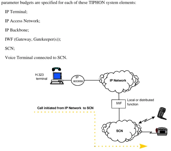
The diagrams below show the four TIPHON Scenarios and the various elements within each TIPHON system. QoS parameter budgets are specified for each of these TIPHON system elements:
- IP Terminal; - IP Access Network; - IP Backbone;
- IWF (Gateway, Gatekeeper(s)); - SCN;
- Voice Terminal connected to SCN.
Call initiated from IP Network to SCN
SCN IP Network
IWF
Local or distributed function
H.323
terminal IP access
Call initiated from SCN to IP Network SCN
IP Network
IWF Local or distributed function H.323 terminal
IP access
Figure 2: Scenario 2 - Call from SCN to IP Network
Phone
SCN
Phone
SCN
IP Network
IWF
IWF IWF
Figure 3: Scenario 3 - SCN to SCN over IP network
IP Network SCN
Client Client
IP Network
Handset Handset
IP Access IP Access
IWF IWF
5
End-to-end Quality of Service
5.1
Introduction
End-to-end QoS in a TIPHON system is characterized in the present document under two broad headings: - call set-up quality; and
- call quality.
Call set-up quality is mainly characterized by the call set up time i.e. the time elapsed from the end of the user interface command by the caller (keypad dialling, email alias typing, etc) to the receipt by the caller of a meaningful tone. ITU-T Recommendation E.600 [6] provides more information on the definition of post dialling delay in SCN systems. Call set-up time is perceived by the user as the responsiveness of the service. Other factors such as ease of use also contribute to the User experience. The first of these factors is objective, the second subjective.
Within the broad category of call quality two major factors contribute to the overall QoS experience of the user of the TIPHON system:
- end-to-end delay: this mainly impacts the interactivity of a conversation. The measurement is done from the mouth of the speaker to the ear of the listener; and
- end-to-end speech quality: this is the one way speech quality as perceived in a non interactive situation. Connection reliability and call set-up accuracy are also factors that contribute to QoS. In the context of TIPHON systems the characterization of these is for further study.
Echoes will also contribute to end-to-end speech quality and the User/Customer tolerance to these echoes decreases with increasing end-to end delay. Echoes may be generated in the terminal by acoustic feedback from the loudspeaker to microphone or within the network by 2 to 4 wire hybrids.
In the first case it is assumed that the choice of the acoustic devices associated with a TIPHON terminal is a user prerogative and therefore the specification of their characteristics is deemed to be outside the scope of the TIPHON project. It is assumed that where appropriate (e.g. loudspeaking telephones or separate speakers and microphone) that adequate echo cancellation is present in the acoustic devices or the TIPHON terminal to ensure that echoes do not contribute to the end-to-end QoS levels. ITU-T Recommendation P.310 [24] provides guidance for handset terminals. In the case of listener and talker echoes arising from 2 to 4 wire hybrids in the SCN it is assumed that suitable echo control takes place either in the SCN itself or in the TIPHON gateways to ensure that any resulting echoes do not contribute to the end-to-end QoS levels. As this is a problem associated with the SCN, and well established techniques exist for echo control in SCN networks, this factor is again assumed to be outside the scope of the TIPHON project and that suitable measures will have been taken within the SCN or the TIPHON gateways to ensure that such echoes do not affect QoS levels in the TIPHON system. ITU-T Recommendation G.131 [13] provides guidance on network
echo-control.
In general, echo cancellers should satisfy the requirements of ITU-T Recommendation G.168 [14].
The following components may be present in a TIPHON system and may each contribute to the overall end-to-end QoS performance of the system:
- an IP terminal; - an IP access network; - an IP backbone;
- one or more IWFs (gateway/gatekeeper(s)); - one or more SCN(s);
5.2
Call Set-Up Quality
The following factors contribute to the overall call-set up time within a TIPHON system:
- IP access network set up delays (these would include transport layer set up-times, modem training times and log on times at the ISP Gateway);
- signalling delays across the IP backbone; - call set-up delays within the gatekeeper(s);
- access times and call processing delays to back-end services such as directory services or authentication services;
- call set-up delays within the gateway; - call set up times in the SCN(s).
5.3
Call Quality
5.3.1
End-to-end delay
One of the main QoS factors in voice transmissions is the delay perceived by the users. In order to allow a normal conversation over a network, this delay has to be kept almost constant and below a defined bound. If the end-to-end delay is too high, an interactive communication is difficult or impossible.
Several studies about delay have been conducted and reported in the scientific literature; they lead to the following conclusions (see ITU-T Recommendation G.114 [10], ETR 250 [1] and ETR 275 [2]):
- small delays (10-15 ms) are not annoying for users, thus controllers for acoustic and electric echo are not needed because the users do not perceive this effect as an echo. This is due to the intrinsic characteristics of the human ear;
- delays up to 150 ms require echo control but do not compromise the effective interaction between the users; - if the delays are in the range 200 to 400 ms, the effectiveness of the interaction is lower but can be still
acceptable;
- if the delay is higher than 400 ms, interactive voice communication is quite difficult and conversation rules are required (as for "Walkie Talkie" communications).
Packet switched data networks also have another problem: delay is usually variable. While telephone services require fixed delay transmissions, data networks cannot provide it because of their "best effort" policies; different packets may have different delays because of traffic conditions: this variation is usually known as network jitter. This variability in the delay also creates the possibility of asymmetric links, in which delays may be different in the two directions of the conversation.
It is assumed in TIPHON systems that end-to-end delay between the speaker and listener is fixed for the duration of a call and that jitter will have been removed by buffering in the system.
This delay is the sum of several factors. Some factors are due to terminal equipment (such as codec delay or audio card buffering), others are due to the network (such as transmission delay). In the following subclauses the contribution of each of these factors is described.
5.3.1.1
IP terminal buffering delay
Audio cards and telephone cards usually include large internal buffers, in order to provide a fixed rate interface to A/D and D/A converter and an asynchronous interface to the application layer.
Additionally, modems and network adapters use internal buffers to increase network access efficiency. They have been optimized for data transmission where delay is not a problem, but this optimization may not be appropriate for voice transmission where delay is a critical issue.
There are also software buffering delays. Application or device drivers can store large amounts of data in order to process them easily and efficiently or to manage the delay jitter in received packets.
5.3.1.2
ITU-T Recommendation H.323 packetization/buffering delays
These delays are two sides of the same coin. Packetization delay may be introduced while packets are being constructed. Buffering delay may be introduced when they are being disassembled.
Packetization delay is the time taken for enough information to fill a whole packet, or until enough information is available, before sending it to the network.
When fixed length packets are used with a frame-oriented codec, packetization can introduce an additional delay if the packet length differs from the codec frame length (see subclause 5.3.2.4). On the other hand if variable length packets are used, packetization delay can be always set to zero if the packet length is equal to the codec frame length. This of course requires careful implementation in order to avoid any intermediate buffering.
Buffering delay is due to queuing in the receiver. Buffering delay is usually used for network jitter compensation. Voice playback requires equally spaced (in time) packets but network delays are variable, thus the receiver will delay early arriving packets to synchronize them with those arriving later. Otherwise a gap may occur in the playback.
5.3.1.3
Codec delay
Many speech coders work on the principle of taking a group of speech samples (usually sampled at 8 KHz) and
simultaneously processing this group of samples to produce a block of data representing the speech in compressed form. This block of data is known as a speech frame. The coded speech frame cannot be generated until all the speech samples in the group to be processed are fed into the coder. There is, therefore, a delay through the encoder equivalent to the length of the group of speech samples to be processed. The length of this group of speech samples is called the frame size of the coder.
In fact, further delays in the speech coder take place:
- processing delay before the output frame is generated;
- an algorithmic process called look-ahead in which some of the samples from the following frame are used to improve the performance of the compression process; and
- as a result of the rate at which the output frame is serially clocked out from the encoder output buffer, if this rate is chosen to provide a continuous bit stream without gaps a further frame delay is involved.
Thus, the delay through the encoder is normally assumed to be: - 2 xframe size + look-ahead + processing delay.
In the decoder a further delay is assumed to allow for further processing delay and the use of an output buffer. The total processing delay through both encoder and decoder is assumed to be less than the length of this output buffer which is usually chosen as one voice frame.
This leads to the rule of thumb for the delay through a speech encoder/decoder pair: - 3 xframe size + look-ahead.
If multiple voice frames are grouped together into a single IP packet, further delay is added to the speech signal. This delay will be the duration of one extra voice frame for each additional voice frame added to the IP packet.
5.3.1.4
Network transmission delays
See the four TIPHON Scenarios illustrated in clause 4.
Transmission delay is the time spent by packets to reach their destination during transmission through the network. There are five main components:
- the transmission delay, introduced by sending a packet over a link. (e.g. sending a 256 byte packet over a 64 kbit/s link takes 32 ms);
- the propagation delay, due to signal propagation over physical link. This delay is usually negligible if links are shorter than 1 000 km;
- the node delay, due to router queuing and processing of packets;
- the protocol delay, due to packet retransmissions (if used, like for TCP) or network access (e.g. CSMA-CD for Ethernet);
- gateway delay, introduced by interfacing between networks (e.g. packet disassembly/assembly and speech coding/decoding).
Network transmission delays are usually negligible in fixed SCNs but are not negligible for wireless SCNs or data networks (e.g. modem links or IP networks).
5.3.2
End-to-end Speech Quality
Speech quality is generally characterized by comparative subjective ratings (Mean Opinion Scores) generated in controlled listening tests. Because MOS scores are subjective, MOS ratings for a system under test are always compared with a well established reference. Several factors in the TIPHON system will contribute to the overall MOS rating of the end-to-end speech quality and will require individual optimization to achieve the best overall MOS rating for the system. The recommended test method for listening-only tests is the 'Absolute Category Rating' (ACR) method.
ITU-T Recommendation P.800 [26] provides general guidance and ITU-T Recommendation P.830 [27] provides detailed guidance for evaluation of speech codecs.
A alternative approach is based on objective measurement of speech quality. ITU-T Recommendation P.861 [28] describes the application of this test method in narrow-band speech systems.
Various five-point category-judgement scales are used in the ACR tests. The following Listening-quality scale is most frequently used for ITU-T applications and is also recommended to be used for TIPHON system evaluations.
Table 1
Quality of speech Score
Excellent 5
Good 4
Fair 3
Poor 2
Bad 1
5.3.2.1
Audio input and output devices
There are three main types of input and output devices; telephone handsets, headsets with microphone and stand-alone microphones together with separate loudspeakers. Handsets and headsets provide specified means to control input and output levels. Usually the frequency characteristics are also well suited for telephony. Acoustic echo is also less of a problem since the acoustic coupling loss is generally in the range of 40 dB to 50 dB. Usually handsets and headsets provide significantly higher background noise rejection than stand-alone microphones. When stand-alone microphones and speakers are used in handsfree situations, the performance is highly dependent on several factors, including the linearity of the equipment and their positioning. The acoustic coupling also need proper echo-control in the form of half-duplex switching solutions or full-half-duplex echo cancellation solutions. The echo canceller has to cope with background noise (e.g. office environment) and double-talk conditions (when users speak at the same time), and cancel the echo in single-talk (normal working) conditions. Poor echo performance mainly affects the user at the other end of the connection.
The sending and receiving frequency response of microphones, loudspeakers, ear-pieces and headsets should be matched to the audio bandwidth used. For narrowband telephony the bandwidth should be 300 Hz to 3 400 Hz with a flat frequency response (within ± 3 dB). If frequencies below 300 Hz are not removed, there is an increased risk that the quality will be degraded due to breathing noise and excessive noise pickup.
5.3.2.2
Analogue/Digital - Digital/Analogue circuit noise
A/D and D/A converters affect quality via their resolution (number of valid bits), the quantization noise it introduces and any non-linear characteristics. For acceptable performance for narrowband speech, a resolution of 12 to 13 bits (linear quantization) is required, and 16 bits is desirable. The circuit noise from A/D, D/A converters and amplifiers should not exceed a level of -70 dBoV. In the SCN the characteristics of 64 kbps G.711 circuits limit the resolution of the overall TIPHON system to 8 bits (algorithmic quantization). ITU-T Recommendation G.711 [15] companding effects shall be linearized prior to compression by a speech codec.
The DC-component from the AD-converter should preferably not exceed 1 % of the maximum output value.
5.3.2.3
Speech Coding Distortion
The speech codec introduces degradation in the perceived quality of speech. In general, the MOS rating of the coder is affected by a number of environmental factors and impairments. The following factors affect the speech quality of specific codecs:
- clean speech performance; - background noise performance;
- signal Levels; especially for lower rate speech coders, the input audio levels affect the quality significantly. The nominal Active Speech input Level (ASL) [37] should for ordinary use be -22 to -26 dBov. Deviations by more than ± 10 dB may create unacceptable degradation due to the speech codec over or under loading. When interfacing to SCN networks it is critical to maintain the nominal send levels for acceptable quality; - robustness to lost frames;
- error mitigation techniques (frame erasure concealment/forward error correction).
5.3.2.4
Effect of Grouping Multiple Codec Frames into a Single Packet
An effect of grouping multiple speech frames into a single IP packet is degraded speech quality when packets are lost. The effect of losing a single speech frame when a packet is lost containing one speech frame will be much less than the effect of losing several adjacent speech frames when a packet is lost which contains multiple speech frames.
5.3.2.5
Effect of Tandeming of Codecs
In general the following principles apply to tandeming of the speech encoding-decoding process:
- tandeming leads to a degradation in speech quality;
- the more tandem encoding/decoding take place the worse the degradation;
- the higher the compression ratio of the coder, i.e. the lower the bit rate, the worse the coder's tandeming performance;
- as speech coders are highly non-linear the effects of tandeming are non-linear and difficult to predict.
In the absence of subjective listening test results the following conclusions can be drawn from the above four principles (not taking into account other non-codec related QoS factors):
- use of a G.711 codec in the VoIP terminal will lead to toll quality results on the PSTN and ISDN and normal GSM performance when terminated on a GSM connection;
- use of a low bit rate coder will lead to a degradation in performance below the normal narrow band
encoding/decoding process due to the tandeming with G.711 coding which takes place in the gateway. (Coders normally operate with 16 bit linear speech samples);
- configuration C (see subclause 5.5.1.1) in which a low bit rate coder is used to generate VoIP traffic and the call is terminated on a GSM network will almost certainly lead to poor results because of the multiple tandem codings involved (three) and the low bit rate of the VoIP coder;
- it would be expected that GSM HR would lead to a further deterioration in quality and GSM EFR an improvement in quality in Configuration C;
- it would be expected that use of a lower bit rate VoIP coder would lead to a deterioration in quality and a higher bit rate VoIP coder would lead to an improvement in quality in Configuration C. This extent of this sensitivity would be coder dependent however.
5.3.2.6
Effects of Bandwidth Limitation in the IP Network
Given suitable optimization of bandwidth (as itemized above), almost any link mechanism will suffice for audio communication (from high-performance modems upwards). The problems start to arise when the audio communication is concurrent with data collaboration. If the data bandwidth demands are too high, either the audio will suffer, or the data communications will break down (depending on how well optimized the communication is for real-time). Obviously, higher bandwidth links (like ISDN, Cable, ADSL) can mitigate this problem.
5.3.2.7
Planning guidelines for handling Impairment effects
All the effects, described in subclause 5.3.2 affect the quality of speech communication. Currently there are two recommended approaches which may be used by network designers and transmission planners to describe and plan for handling such impairment effects. One approach, "the Quantization Distortion Method", is preferred in planning the use of PCM codecs (ITU-T Recommendation G.711 [15]). The other approach "the Equipment Impairment Factor Method" (ITU-T Recommendation G.113 [9]), is intended for use in planning the deployment of low bit rate coders. The
5.4
QoS Issues Associated with each component of the
TIPHON System
5.4.1
QoS Issues Associated with the IP Terminal
The following factors in the IP terminal will have an impact on QoS: - the choice of speech codec used in the terminal;
- the performance of the speech codec to various types of network degradation (including effects of any error concealment mechanisms present in the coder);
- the acoustic interface; - signal processing delays; - call processing delays;
- number of speech frames per packet;
- processing delays associated with security issues; - the design of jitter buffers;
- delays through the audio or digital media paths;
- the performance of acoustic echo-cancelling devices.
5.4.2
QoS Issues Associated with the IP Access Network
A variety of access network transport media may be used to interconnect TIPHON IP terminals with IP backbone networks. EG 202 306 [3] provides guidelines. Examples of methods that can be used for IP access layer transport are:
- LAN Access;
- PSTN Access; - xDSL Access; - Cable Modem Access; - BRAN Access; - DECT Access; - UMTS Access; - ISDN Access; - GSM Access.
5.4.2.1
LAN Access
In this configuration the access layer is limited to the Network Interface Card (NIC) used within the IP terminal. Though the LAN has ample bandwidth for transmission of coded speech, a fundamental issue frequently encountered is
contention for shared media. At any time, other (non audio) endpoints on the LAN may flood the LAN and consume all the available bandwidth. This problem can only be avoided if there are mechanisms to manage and police the use of bandwidth (both for real-time use and best-effort use). The Subnet Bandwidth Manager (SBM), and RSVP
(IETF RFC 2205 [31]) are intended to provide this capability. Factors affecting QoS in this scenario are:
- transmission delays through NIC; and - jitter in data buffers associated with the NIC.
It is anticipated that these parameters will in general be well controlled and specification of upper bounds on these parameters should present few difficulties.
5.4.2.2
PSTN Access
In this type of access, modems are used to establish a digital channel between the TIPHON terminal and the IP network. Factors affecting QoS in this configuration are:
- Modem Bit rate;
- use of PPP/IP/UDP/RTP header compression on access link (see IETF RFC 2508 [36]); - modem transmission overheads;
- throughput delay in modem and at ISP site;
- jitter within client modem, ISP modem and PPP buffers;
- PSTN set-up time;
- modem connection set-up time; - ISP logon & PPP set-up time; and - error rate on PSTN link.
5.4.2.3
xDSL Access
xDSL access allows the use of various sizes of bandwidth, up to tens of Mbit/s, depending on application and the DSL technique used (e.g. ADSL, VDSL).
IP access may use in general a mediation transport layer, i.e. ATM, or be mapped directly into the xDSL frame (not standardized yet).
Factors affecting QoS in this scenario are:
- xDSL modem available bit rate (due to line condition and specific application); - use of PPP/IP/UDP/RTP Header Compression on access link;
- throughput delay in xDSL modem (Fast or interleaved) and at ISP site;
- jitter within client modem, ISP modem and adaptation buffers;
- xDSL set-up time (e.g. when using Dynamic Power Save in VDSL application); - ISP Logon & session set up time; and
5.4.2.4
ISDN Access
ISDN access uses a set bandwidth for the communication channel (16 kbit/s for the D channel, 64 kbit/s for a B channel). Aggregation of 2 B channels to provide a 128 kbit/s channel provides a means of using
ITU-T Recommendation G.711 [15] codecs even with normal RTP/UDP/TCP/IP overheads. Transmission of IP speech packets over the D channels is possible using narrow band speech codecs and header compression.
Factors affecting QoS in this scenario are:
- use of PPP/IP/UDP/RTP header compression on access link; - throughput delay in ISDN terminal adapter and at ISP site;
- jitter within ISDN terminal adapter and ISP network interface buffers; - ISDN set-up time; and
- ISP Logon & session set-up time.
5.4.2.5
GSM Access
IP access over GSM is possible via a GSM terminal adapter. With existing systems rates are limited to 9,6 kbit/s necessitating the use of narrow band speech codecs and header compression.
Factors affecting QoS in this scenario are:
- use of PPP/IP/UDP/RTP header compression on access link;
- throughput delay in GSM terminal adapter and at ISP site;
- jitter within GSM terminal adapter and ISP network interface buffers; - GSM data link set-up time;
- ISP logon & PPP set-up time; and - error rate on GSM link.
5.4.2.6
Cable Modem, BRAN, DECT, UMTS Access
See EG 202 306 [3].
5.4.3
QoS Issues Associated with the IP Backbone
Routing through the network (e.g. the number of hops) will increase transmission delay. Traffic congestion on the network will lead to packet loss and delay jitter.
5.4.4
QoS Issues Associated with the Gateway/Gatekeeper(s)
Factors affecting QoS in the Gateway mirror those in the IP terminal: - the choice of speech codec used;
- transcoding(s) or Tandem Free Operation with the SCN;
- the performance of the speech codec to various types of network degradation (including effects of any error concealment mechanisms present in the coder);
- signal processing delays; - call processing delays; - the packetization method used;
- processing delays associated with security issues; - the design of jitter buffers;
- delays through the audio or digital media paths; - the performance of network echo-cancelling devices; - DTMF tone handling.
Factors affecting QoS in the Gatekeeper include: - call processing delays;
- processing and look-up delays associated with security issues; - delays in accessing back-end services.
5.4.5
QoS Issues Associated with the SCN
5.4.5.1
Network echo control
In telephone applications, the network echo is generated by impedance mismatch occurring at four-wire to two-wire transitions (hybrids).
If no echo control is present (in the form of either echo cancellers or echo suppressors which ensure a high echo return loss), the user who speaks will hear the echo of his voice delayed by twice the value of the mean one way delay, strongly compromising system QoS. In connections interfacing to the PSTN, network echo control is to be employed.
The usual location for the echo canceller is in the Gateway interface towards the PSTN or alternatively in the telephone exchange for those interfaces that are linked to the Gateway.
In principle, interfaces with GSM and ISDN, being entirely four-wire systems, do not need network echo control to control electrical echoes. However, for interfaces with ISDN terminated by PSTN echo control is necessary.
5.4.6
QoS Issues Associated with the Voice Terminal Connected to the
SCN
5.5
Issues Specific to each TIPHON Scenario
5.5.1
Scenario 1
5.5.1.1
Tandeming of Speech Codecs
Four different speech compression configurations are possible within a TIPHON Scenario 1 system:
a) a VoIP terminal using a narrowband codec (say ITU-T Recommendation G.723.1 [16] operating at 6,4 kbit/s) is connected through a 64 kbit/s ISDN channel or PSTN modem connection to an IP network and the speech signals then converted via an IP/PSTN gateway to 64 kbit/s PCM format and then at the local exchange to analogue signals;
b) a VoIP terminal using a 64 kbit/s G.711 codec is connected via a LAN to an IP network and the speech signals then converted via an IP/PSTN gateway to 64 kbit/s PCM format then at the local exchange to analogue signals; c) a VoIP terminal using a narrowband codec (say ITU-T Recommendation G.723.1 [16] operating at 6,4 kbit/s) is connected through a 64 kbit/s ISDN channel or PSTN modem connection to an IP network and the speech signals then converted via an IP/PSTN gateway to 64 kbit/s PCM format and in this form then pass into a GSM network. At the GSM base station they are compressed to 13 kbit/s (in the case of FR GSM FR or some other bit rate in the case of GSM HR or EFR) then transmitted over a wireless connection to a GSM terminal where they are converted to analogue speech;
d) a VoIP terminal using a 64 kbit/s ITU-T Recommendation G.711 [15] codec is connected via a LAN to an IP network. The speech signals are then converted via an IP/PSTN gateway to 64 kbit/s PCM format and in this form then pass into a GSM network. At the GSM Base Station System they are then compressed to 13 kbit/s (in the case of GSM FR or some other bit rate in the case of GSM HR or EFR) then transmitted over a wireless connection to a GSM terminal where they are converted to analogue speech;
In the future a fifth speech compression scenario may be possible:
e) A VoIP terminal using a GSM codec (FR, HR or EFR) is connected through a 64 kbit/s ISDN channel or PSTN modem connection to an IP network and the speech signals in this form then pass into a GSM network. At the GSM Base Station System they are transmitted without transcoding over a wireless connection to a GSM terminal containing the same codec where they are converted to analogue speech.
The Speech Coding and Decoding Processes that take place in each of the above scenarios is illustrated below.
G.711 G.711
G.72x G.72x
VOIP TERMINAL
ANALOGUE PHONE LOCAL
EXCHANGE GATEWAY
G.711 G.72x
VOIP TERMINAL
ANALOGUE PHONE LOCAL
EXCHANGE GATEWAY
Figure 6: Configuration B
GSM G.711
G.711 G.72x
GSM PHONE
GSM G.72x
GSM BASESTATION VOIP
TERMINAL
GATEWAY
Figure 7: Configuration C
GSM G.711
GSM PHONE
GSM G.711
GSM BASESTATION VOIP
TERMINAL
GATEWAY
Figure 8: Configuration D
GSM PHONE
GSM GSM
GSM BASESTATION VOIP
TERMINAL
GATEWAY
Figure 9: Configuration E
5.5.2
Scenario 2
For further study.
5.5.3
Scenario 3
5.5.4
Scenario 4
For further study.
6
QoS Classes in TIPHON Systems
6.1
Definition of TIPHON QoS Classes
Four classes of QoS are defined for TIPHON systems. The TIPHON QoS definitions include both the network and the TIPHON terminal characteristics but exclude the acoustic characteristics of the terminals:
- Best: This is a type of IP telephony service that has the potential (depending on the acoustic properties of the TIPHON terminal) to provide a user experience similar to PSTN or even better. It is expected to be implemented over QoS engineered IP networks and LAN environments.
- High: This is a type of IP telephony service that has the potential (depending on the acoustic properties of the TIPHON terminal) to provide a user experience similar to PSTN (or e.g. recent wireless mobile telephony services in good radio conditions, for instance GSM networks using EFR codecs or devices using
ITU-T Recommendation G.726 [17]) but with increased delay. It is also expected to be implemented over QoS engineered IP networks when trying to optimize bandwidth usage.
- Medium: This is a type of IP telephony service that has the potential (depending on the acoustic properties of the TIPHON terminal) to provide a user experience similar to common wireless mobile telephony services, for instance GSM networks using FR codecs. It is expected to be implemented over uncongested IP networks. - Best Effort: This type of service will provide a usable communication but with significantly impaired speech
quality, and end-to-end delays are likely to impact the overall conversational interactivity, no upper bound on delays is required. The perceived voice quality will be less than, for instance, GSM FR. It is expected to be provided over the public Internet.
To fall in one of those categories, the TIPHON system shall comply with minimal characteristics for the three parameters that have a significant impact on the user experience:
- Oneway non-interactive end-to-end Speech Quality; - End-to-end Delay;
- Call set-up time.
The classification and measures of speech quality used for TIPHON systems exclude the acoustic and related
characteristics of TIPHON terminals (including echo return loss) and apply only to the path from the electrical input of one terminal through the network to the electrical output of the other terminal. Acoustic and related characteristics of terminals have been excluded in order to:
- focus on the parameters specific to TIPHON (i.e. where TIPHON systems differ from existing SCN systems); - avoid the problems of measurement and characterization associated with forms of acoustic systems other than traditional handsets. These measures therefore do not describe the full acoustic-acoustic (mouth to ear) quality that will be experienced by a user, which is dependent on the acoustic quality of the terminal as well as the quality of the TIPHON system. Care should be taken not to confuse the approach used for TIPHON systems with the more general and more complete approach to end-to-end quality. In the present document he term "TIPHON speech quality" refers to the first of these definitions.
6.2
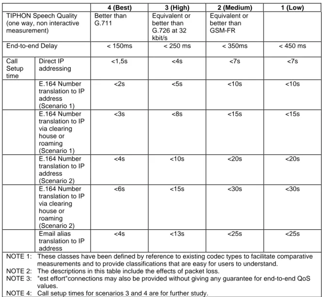
TIPHON End-to-End QoS Budgets
Table 1a: End-to-end QoS Classes for TIPHON Systems
4 (Best) 3 (High) 2 (Medium) 1 (Low)
TIPHON Speech Quality (one way, non interactive measurement)
Better than G.711
Equivalent or better than G.726 at 32 kbit/s
Equivalent or better than GSM-FR
End-to-end Delay < 150ms < 250 ms < 350ms < 450 ms
Call Setup time
Direct IP addressing
<1,5s <4s <7s <7s
E.164 Number translation to IP address (Scenario 1)
<2s <5s <10s <10s
E.164 Number translation to IP via clearing house or roaming (Scenario 1)
<3s <8s <15s <15s
E.164 Number translation to IP address (Scenario 2)
<4s <10s <20s <20s
E.164 Number translation to IP via clearing house or roaming (Scenario 2)
<6s <15s <30s <30s
Email alias translation to IP address
<4s <13s <25s <25s
NOTE 1: These classes have been defined by reference to existing codec types to facilitate comparative measurements and to provide classifications that are easy for users to understand.
NOTE 2: The descriptions in this table include the effects of packet loss.
NOTE 3: "est effort"connections may also be provided without giving any guarantee for end-to-end QoS values.
NOTE 4: Call setup times for scenarios 3 and 4 are for further study.
N.B. All delay parameters represent an upper bound for 90% of the connections over the TIPHON system.
Table 1b: Overall Transmission Quality Rating for TIPHON Systems
TIPHON QoS Class 4 (Best) 3 (High) 2 (Medium) 1 (Low)
Overall Transmission Quality Rating
> 90 80 – 89 70 – 79 60 - 69
User’s satisfaction (from ITU-T)
Very satisfied Satisfied Some users dissatisfied
Many users dissatisfied NOTE 1: The values given in the row ‘Overall transmission quality rating’ are provisional.
NOTE 2: The descriptions in this table include the effects of packet loss.
6.3
TIPHON Terminal Device Classification
TIPHON terminals need to be designed to interwork with and match the quality characteristics of TIPHON networks. The end-to-end quality perceived by the user depends strongly on how well the terminals and networks are matched. Because there is a wide spread in network characteristics, three different classes of terminal have been defined, each
specified to match a particular range of IP network characteristics. Table 2 relates the terminal classes to the network characteristics that the terminals are designed to match, together with the typical end-to-end performance objective.
Table 2: Relationship between Terminal Class and Achievable System Performance Terminal Class Network Characteristics Performance Objective achievable for
terminal - network combination
Class A High bandwidth, e.g. Intranets based on LANs High-Best Class B Medium bandwidth (< 64 kbit/s), e.g. Intranets
with rather limited capacity or connection to the Internet via ISDN
Medium - High
Class C Low bandwidth (< 25 kbit/s) e.g. connections to the Internet via a modem link.
Best effort - Medium
The distinction between the terminals types relates to the intended application or market, and therefore class A should not be considered to be inherently "better" than class B.
A terminal equipment may be designed to implement more than one coding scheme and therefore may be capable of providing more than one class of performance.
A terminal of class A may perform very poorly with a network of low bandwidth or be totally incompatible with it. In order to design a terminal capable of working with any network characteristic, a manufacturer has either to design to class C and accept limited performance with better networks, or design a terminal that can adapt to the bandwidth characteristics of the network, i.e. it should implement more than one terminal class and be able to adapt its class to match the network bandwidth characteristics.
The performance of IP based networks will vary with time depending on a range of factors such as traffic loading. Consequently the design of the terminals needs to be able to accommodate these variations. The main variables affecting terminal performance are:
- packet loss; - delay jitter.
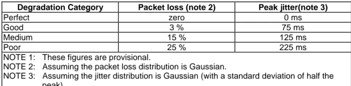
Four categories of network degradation are defined as in table 3 (note 1):
Table 3: Levels of network degradation
Degradation Category Packet loss (note 2) Peak jitter(note 3)
Perfect zero 0 ms
Good 3 % 75 ms
Medium 15 % 125 ms
Poor 25 % 225 ms
NOTE 1: These figures are provisional.
NOTE 2: Assuming the packet loss distribution is Gaussian.
NOTE 3: Assuming the jitter distribution is Gaussian (with a standard deviation of half the peak).
The performance classes of the terminals are therefore defined for the matching network with a range of degradations, i.e. a performance envelope is defined for each terminal class and a terminal should meet the performance limits of the whole envelope. This approach should ensure that terminals are designed both to match networks and to provide an adequate degree of robustness in performance.
Although the design of a terminal requires exact conformance to the coding algorithm for the encoding direction, manufacturers may innovate in the design of the decoding algorithm and may trade-off decoding delay against performance for example by using interpolation to reduce the effects of packet loss. Consequently the performance envelope for the terminals is defined to allow this trade-off.
The performance envelopes for TIPHON speech quality are specified for an end-to-end connection with terminals of the given class at each end.
6.3.1
Class A TIPHON Terminal Devices
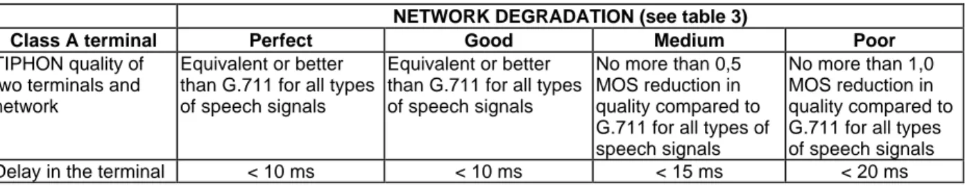
Class A devices are typically used in Intranets where the bandwidth available is sufficient to use low compression rates and redundancy if necessary. Those devices are expected to provide a high interactivity (low delays), and a sound quality comparable or better than G.711. Table 4 specifies the performance envelope for class A devices.
Table 4: Terminal performance envelope for class A terminals with a network
whose bandwidth is greater than that required by the terminal (i.e. the terminal is not constrained) NETWORK DEGRADATION (see table 3)
Class A terminal Perfect Good Medium Poor
TIPHON quality of two terminals and network
Equivalent or better than G.711 for all types of speech signals
Equivalent or better than G.711 for all types of speech signals
No more than 0,5 MOS reduction in quality compared to G.711 for all types of speech signals
No more than 1,0 MOS reduction in quality compared to G.711 for all types of speech signals Delay in the terminal < 10 ms < 10 ms < 15 ms < 20 ms
6.3.2
Class B TIPHON Terminal Devices
Class B devices can be used in Intranets where the bandwidth budget is more tight (64 kbit/s per sound channel), or by users having a good connection (typically, via ISDN) to the internet. Table 5 specifies the performance envelope for class B devices.
Table 5: Terminal performance envelope for class B terminals with a network whose bandwidth is < 64 kbit/s
NETWORK DEGRADATION (see table 3)
Class B terminal Perfect Good Medium Poor
TIPHON quality of two terminals and network
Equivalent or better than G.726 at 32 kbit/s for all types of speech signals
Equivalent or better than G.726 at 32 kbit/s for all types of speech signals
No more than 0,5 MOS reduction in quality compared to G.726 at 32 kbit/s for all types of speech signals
No more than 1,0 MOS reduction in quality compared to G.726 at 32 kbit/s for all types of speech signals Delay in the terminal < 40 ms < 40 ms < 50 ms < 60 ms
6.3.3
Class C TIPHON Terminal Devices
Class C devices can be used on the Internet where the bandwidth is restricted. These devices cannot use more bandwidth than typically available through a modem and therefore need codecs with high compression rates. The speech quality will be degraded although still understandable, and the delay budget may grow due to increased coding/decoding delays and increased jitter buffers. Table 6 specifies the performance envelope for class C devices.
Table 6: Terminal performance envelope for class C terminals with a network whose bandwidth is < 25 kbit/s
NETWORK DEGRADATION (see table 3)
Class C terminal Perfect Good Medium Poor
TIPHON speech quality of two terminals and network
Equivalent or better than GSM FR for all types of speech signals
Equivalent or better than GSM FR for all types of speech signals
No more than 0,5 MOS reduction in quality compared to GSM FR for all types of speech signals
No more than 1,0 MOS reduction in quality compared to GSM FR for all types of speech signals Delay in the terminal < 60 ms < 60 ms < 80 ms < 100 ms
6.4
Network Delay Characterization
Table 7 shows the requirements on transmission delay across a network for the achievement of a given level of TIPHON end-to-end quality with a specified class of terminal. (NB: Delay is not the only network factor in achieving TIPHON end-to-end quality and therefore this is a necessary but not sufficient requirement).
Table 7a applies to Scenarios 1 & 2 where one IP terminal is involved in the connection. Table7b applies to Scenario 3 with no IP terminals involved and Table 3c applies to Scenario 4 with two IP terminals involved.
Table 7a: TIPHON Network Delay Requirements (Scenarios 1 & 2) TIPHON QoS Class Terminal A
(10-20 ms)
Terminal B (40-60 ms)
Terminal C (60-100 ms)
4 Best <150 ms <130 ms Not achievable because of other
factors
Not achievable because of other
factors 3 High <250 ms <230 ms <190 ms Not achievable
because of other factors 2 Medium <350 ms <330 ms <290 ms <250 ms 1 Low <450 ms <430 ms <390 ms <350 ms NOTE: Delay in the IWF is included in the network delay requirements.
Table 7b: TIPHON Network Delay Requirements (Scenario 3) TIPHON QoS Class Network Delay Requirements
4 Best <150 ms <150 ms
3 High <250 ms <250 ms
2 Medium <350 ms <350 ms
1 Low <450 ms <450 ms
NOTE: Delay in both IWFs is included in the network delay requirements.
Table 7c: TIPHON Network Delay Requirements (Scenario 4) TIPHON QoS Class Terminal A
(10-20 ms)
Terminal B (40-60 ms)
Terminal C (60-100 ms)
4 Best <150 ms <110 ms Not achievable because of other
factors
Not achievable because of other
factors 3 High <250 ms <210 ms <130 ms Not achievable
because of other factors 2 Medium <350 ms <310 ms <230 ms <150 ms 1 Low <450 ms <410 ms <330 ms <250 ms NOTE: Delay in both IWFs is included in the network delay requirements.
NOTE: These values assume the same terminal type is used at each end of the connection. The use of different terminal types at each end will result in different values of permitted network delay.
6.5
Using this subclause
The information in this subclause can be used in any of the following ways:
- manufacturers should decide which class of terminal to develop. They should choose the terminal class to match the characteristics of the networks available to their potential customers. They may wish to design multiple class terminals to address a broader market, or to design a terminal with common hardware capable of supporting different coding algorithms implemented n software;
- users should decide what network - terminal combination they require to provide a particular TIPHON level of service. If they already have a network (e.g. a LAN) they should choose a terminal class to match their network;
- network designers should decide what is the maximum level of quality that they wish to support and its cost implications. e.g. Supporting only a low level of quality will make their network unsuitable for customers whose terminals can only support say class A.
6.6
Further work
End-to-end quality depends on many variables. The approach and characterization given in this subclause considers only some of these variables. In particular the design of the terminal and the environment in which the terminal is used have a very strong effect on the perceived end-to-end quality. Subjective measurements are needed on the quality that can be achieved by PC based terminals.
There is a strong interaction between the performance of codecs and the statistics of network performance, especially cell loss and delay jitter. Work is needed to investigate the robustness of coding algorithms to the performance typical of IP networks. The results of such practical work may make revisions of the performance objectives for the classes in subclause 6.3.
7
Testing of TIPHON Systems
The purpose of this subclause is to provide information on how TIPHON systems and terminals can be tested in order to support conformance statements concerning the class of quality provided.
7.1
Testing of Speech Quality
There are two methods of testing end-to-end (acoustic to acoustic) speech quality:
- subjective tests involving the opinion of panels of users (See ITU-T Recommendation P.800 [26]); - objective tests including comparison methods against a known reference signal (see
ITU-T Recommendation P.861 [28]), absolute estimation methods e.g. based on
ITU-T Recommendation P.561 [25], and the measurement of individual parameters followed by the use of a transmission rating model (TRM) to combine the effects of the individual parameters and predict the subjective views of users. The E-model is under consideration for this purpose. See ETR 250 [1].
Subjective tests have the advantage of including all parameters and providing a direct subjective view, but they take a long time to perform, are costly and are ill-suited to investigating changes in the values of many parameters because of the large numbers of combinations involved.
Objective comparison methods are described in EG 201 377-1 [33].Objective tests using the EModel approach should include the same parameters as in the PSTN world:
- SLR Sending Loudness Rating; - RLR Receiving Loudness Rating; - OLR Overall Loudness Rating;
- STMR Sidetone Masking Rating; - LSTR Listener Sidetone Rating;
- Ds D-Value of Telephone at Send-side; - Dr D-Value of Telephone at Receive-side; - WEPL Weighted Echo Path Loss;
- qdu Number of Quantizing Distortion Units;
- I.e. Equipment Impairment Factor (low bit-rate Codecs); - Nc Circuit Noise referred to the 0 dBr-point;
- Nfor Noise Floor at the Receive-side; - Ps Room Noise at the Send-side;
- Pr Room Noise at the Receive-side.
For evaluation of the I.e. values for low bit-rate codecs, some objective measurement methods have been developed but commercial measurement systems are not yet available. In addition, specific requirements from the TIPHON system (e.g.. packet loss) have to be considered in determining I.e.
In conversational situations:
- TELR Talker Echo Loudness Rating;
- T Mean one way delay of the echo path; and - Tr Roundtrip Delay in a closed 4-wire loop,
need also to be considered.
The performance of TIPHON systems in terms of TIPHON speech quality classes may also be measured between the electrical input/outputs of the TIPHON terminals or SCN telephone terminals connected to the TIPHON system. Figure 10 shows in general how this should be done. Details are for further study.
Reference Codec G.711, G.726
or GSM FR
TIPHON Network Acoustic
Part
Electrical Part
Terminal
Reference Acoustic
Device Test Point
Subjective Comparison ITU-T
recorded speech signals
Electrical Part
Acoustic Part
Terminal
Figure 10: Methodology for testing TIPHON speech quality
Speech quality shall be measured using the subjective test methodology as defined by ITU-T SG12 until such times as calibrated objective methods are possible. It is planned that these test results will be used in the future to enable predictions of overall performance to be made using a TRM (e.g. the E Model). It should be noted that the E model is not a test method.
7.2
Testing of End-to-End Performance
7.2.1
Testing of End-to-End Speech Quality
The methodology and test configuration outlined in subclause 7.1 shall be employed for testing TIPHON terminal speech quality.
7.2.2
Testing of End-to-End Delay
For further study.
7.2.3
Testing of Call Set-Up Time
7.3
Testing of Terminals
7.3.1
Introduction
The critical aspect of performance in terms of the TIPHON quality classes is the ability of the TIPHON terminal to handle performance degradations in the network (packet loss and delay jitter).
Terminals should be tested using pairs of the same terminals and a network simulator as shown in figure 11.
Network Simulator TIPHON Terminal TIPHON
Terminal
Input Signal Output Signal
Figure 11: Methodology for testing TIPHON terminals
The network simulator should be set in turn to produce packet loss and delay jitter performance at the maximum limits for each category specified in table 3, starting with "Perfect". The performance of the terminal and network simulator combination should be measured and the performance of the terminal derived from the results as detailed below:
- if the performance of the terminal complies with the requirements of subclauses 6.3.1 for all levels of network degradation then the terminal provides class A performance;
- if the performance of the terminal complies with the requirements of subclauses 6.3.2 for all levels of network degradation then the terminal provides class B performance;
- if the performance of the terminal complies with the requirements of subclauses 6.3.3 for all levels of network degradation then the terminal provides class C performance.
7.3.2
Measurement of TIPHON Terminal Speech Quality
The methodology outlined in subclause 7.1 shall be employed for testing TIPHON terminal speech quality. TIPHON speech quality tests shall be performed using the test configuration in figure 12.
Reference Codec G.711, G.726
or GSM FR
Network Simulator Acoustic
Part
Electrical Part
TIPHON Terminal
Reference Acoustic
Device Test Point
Subjective Comparison ITU-T
recorded speech signals
Electrical Part
Acoustic Part
TIPHON Terminal Figure 12: Methodology for testing TIPHON terminal speech quality