Volume 21 (2009)
Proceedings of the
3
rd
International Workshop on
Multi-Paradigm Modeling
(MPM 2009)
Model-Based Engineering of Supervisory Controllers using CIF
Ramon R.H. Schiffelers, Rolf J.M. Theunissen, Dirk A. van Beek, and Jacobus E. Rooda
10 pages
Guest Editors: T. Levendovszky, L. Lengyel, G. Karsai, C. Hardebolle Managing Editors: Tiziana Margaria, Julia Padberg, Gabriele Taentzer
Model-Based Engineering of Supervisory Controllers using CIF
Ramon R.H. Schiffelers, Rolf J.M. Theunissen, Dirk A. van Beek, and
Jacobus E. Rooda
∗(r.r.h.schiffelers, r.j.m.theunissen, d.a.v.beek, j.e.rooda)@tue.nl
Department of Mechanical Engineering
Eindhoven University of Technology, P.O.Box 513, 5600 MB Eindhoven, The Netherlands
Abstract: In the Model-Based Engineering (MBE) paradigm, models are the core elements
in the design process of a system from its requirements to the actual implementation of the system. By means of Supervisory Control Theory (SCT), supervisory controllers (supervi-sors) can be synthesized instead of designing them manually. In this paper, a framework based on the Compositional Interchange Format for hybrid systems (CIF) has been developed that integrates the MBE and the SCT paradigms. To illustrate the framework, an industrial-size case study has been performed: synthesis of a supervisory controller for the patient support system of an MRI scanner. In this case study, we address 1) modelling of the components and the control requirements; 2) synthesis of the supervisor; 3) simulation of the synthesized supervisor and a hybrid model of the plant; and 4) real-time, simulation based control of the supervisor and the actual patient support system of the MRI scanner.
Keywords:Model-based engineering, Supervisory control synthesis, Automata, Interchange
formats
1
Introduction
Complex manufacturing machines consist of physical components (hardware) and control systems. The physical components, typically sensors, actuators and main structure, provide the means of the machine. The interactions between the physical components result in the so-called uncontrolled behavior of the machine. The control systems interact with the sensors and actuators to employ the means of the machine, which results in the controlled behavior of the machine. The controlled behavior should be such that the machine fulfills its functions, i.e. meets its pre-defined requirements. The control systems can be divided into five functional subsystems, see [PFC89]: 1) Regulative control(also known as direct or feedback control) that assures that the actuators reach the desired position in the desired way. 2) Error-handling control(also known as fault detection and isolation or exception handling) that detects erroneous behavior, determines the cause, and acts to recover the machine control system. 3)Supervisory control (also known as logic control) that coordinates the control of the individual machine components. This includes planning, scheduling and dispatching functions. 4) Thedata processing subsystemthat stores and manipulates gathered data. 5) Theuser interface subsystemthat allows the user to interact with the machine control system. In this paper, we focus on the development process of supervisory controllers (supervisors).
The current practice of developing supervisory controllers is to code them manually, based on (possibly informal) control requirements. Creating and changing requirements, a design and/or an implementation can be time consuming and error-prone. An other possibility is to use theModel-Based Engineering (MBE) paradigm, see [Ogr00,Bra08], in order to design the supervisory controller. In this case, (pos-sibly formal) executable models for the supervisory controller are developed (by hand). Using analysis
techniques such as simulation and verification, the system controlled by the supervisor can be analyzed. However, the development of a model of the supervisory controller is a highly non-trivial task. An alterna-tive approach is to synthesize the supervisory controller automatically usingSupervisory Control Theory, see [Won07,CL07]. First, the uncontrolled behavior of the machine to control is modeled precisely (by hand). Secondly, the requirements on the function of the machine (with respect to supervisory control) are modeled in detail (by hand). This includes safety and functional requirements. Out of these formal requirements and the model of the uncontrolled system, the supervisory controller can be synthesized automatically. This supervisory controller is proven correct by construction. This means that the con-trolled system behaves according to the prescribed requirements on the function of the machine and that the system is deadlock and lifelock free.
Although Supervisory Control Theory ensures that the controller is proven correct by construction, it remains a non-trivial task (but easier than the development of the supervisory controller itself) to define the correct plant and requirement models, and errors or undesired behavior might still exist in the plant models and/or requirement models.
Therefore, in this paper, we describe a framework developed for supervisory controller design. It combines the model-based engineering paradigm, that enables analysis by means of simulation and ver-ification, together with supervisory control theory, that provides automatic synthesis of supervisors. For example, the plant models that are developed for the supervisor synthesis, can be reused for simulation of these plant models controlled by the synthesized supervisor. Simulation results can be used to validate whether the controlled plant behaves as intended. At a later stage in the design process, more detailed, e.g. timed or hybrid, plant models can be developed. Simulation of the more detailed plant models con-trolled by the synthesized model of the supervisor, enables a more detailed analysis. Early integration and testing can be performed by means of coupling models and realizations of different components via an infrastructure. Finally, the realization of all plant and controller components are integrated into one system.
To support the design process of industrial-size supervisory controllers, a (software) tool framework, based on the Common Interchange Formalism for hybrid systems, see [BRSR07,BRRS07], has been developed. To illustrate this tool framework, we describe an industrial-size case study that has been performed:synthesis of a supervisory controller for the patient support system of an MRI scanner.
The outline of this paper is as follows. Section2 introduces the Model-Based Engineering (MBE) paradigm and Supervisory Control Theory (SCT). The developed framework and the accompanying tools are described in Section3. The industrial-size case study is described in Section4. Section5concludes the paper with conclusions and recommendations of future work.
2
MBE and SCT
This section provides the required background on Model-Based Engineering and Supervisory Control Theory.
2.1
Model-Based Engineering
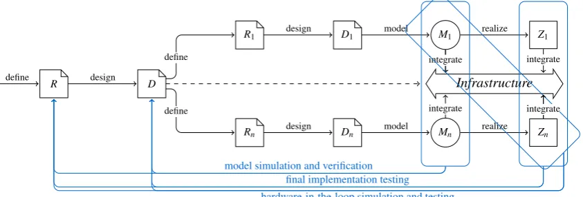
The Model-Based Engineering (MBE) system development process is depicted in Figure11. It starts with defining system requirementsRand creating a system designD. Based on system design the system is divided intoncomponents. For each componenti∈ {1, . . . ,n}requirementsRiare defined and its design
Di is developed. Based on the design of a component, modelsMi are developed, each with their own
purpose and required level of detail. After that, the component implemented resulting in a realizationZi.
The models of the components can be used to perform further functional and performance analysis
R D
R1 D1 M1 Z1
Rn Dn Mn Zn
Infrastructure define
define define design
design
design
model
model
realize
realize integrate
integrate
model simulation and verification
integrate
integrate
hardware-in-the-loop simulation and testing
integrate
integrate
final implementation testing
Figure 1: Model-Based Engineering.
by means of simulation and/or verification techniques such as model checking. Early integration and testing can be performed by means of coupling models and realizations of different components via an infrastructure. At the end, the realization of all components are integrated into one system. To confirm that the resulting system fulfills its requirements, the implemented components and the system as a whole are tested.
2.2
Supervisory Control Theory
Supervisory Control Theory (SCT) has been developed by W.M. Wonham and P.J. Ramadge, and their co-workers, in the 1980’s, see [Won07,CL07]. It allows to synthesize the models of the supervisors, such that the correctness of these models is predetermined. The behavior of the system under control (further on, uncontrolled system) is considered unsatisfactory and has to be restricted by the supervisor to fulfill certain requirements. First, an uncontrolled system and its requirements are formally specified in terms of automata. Then, from these models, the supervisor is derived. The method guarantees that the system consisting of the derived supervisor and the uncontrolled subsystem fulfills the requirements. The theory has been implemented in a software package called TCT, see [Won07]. For large systems, the method suffers a state space explosion problem. To overcome this problem, research has been and is conducted to reduce complexity by using methods such as modular, decentralized and hierarchical control, see [CL07] and references therein.
3
Integrating MBE and SCT
In this section, we present the framework developed for supervisory controller design. It combines the model-based engineering paradigm, that enables analysis by means of simulation and verification, to-gether with supervisory control theory, that provides automatic synthesis of supervisors. Furthermore, we present the developed tool framework that supports the design process.
3.1
Integrating MBE and SCT
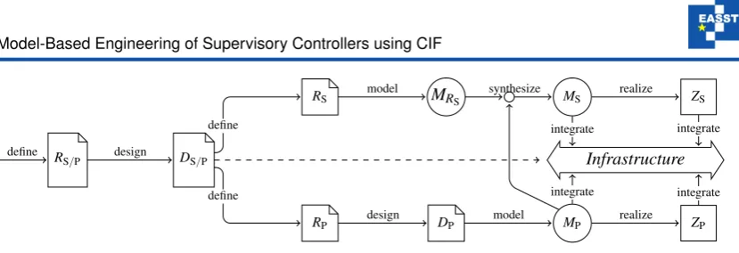
Figure2shows the framework developed for supervisory controller design. From requirementsRS/P2of the controlled system, a designDS/Pof the system is made and decomposed into a plant and a supervisory controller. RequirementsRSof the supervisor are formally modeled resulting in modelMRSof the control
requirements . From plant requirementsRP, a designDPand one or more modelsMPcan be made, each
RS/P DS/P
RS MRS MS ZS
RP DP MP ZP
Infrastructure define
define define design
model
design
synthesize
model
realize
realize integrate
integrate
integrate
integrate
Figure 2: Supervisory controller design framework.
with a different level of detail. For instance, a discrete-event model of the plant can be made that serves as input for the supervisory controller synthesis, while a more detailed (possibly hybrid) model can be developed to study the dynamic behavior of the plant by means of simulation. In this way, simulation of the hybrid plant model and the model of the supervisor can reveal invalid assumptions in the models that are used for the supervisor synthesis. Using SCT, that takes as input the discrete-event model of the plant and the model of the control requirements for the supervisor, the model of supervisorMSis synthesized.
Using this model and the model(s) of the plant, the analysis techniques provided by the MBE paradigm can be used. By means of, for instance, code-generation, a realization of the supervisor can be made.
3.2
Tool framework
In this section we describe the tool-framework that is developed to support the development of supervisors using the integrated MBE and SCT paradigms. The tool-framework uses the Common Interchange Format for hybrid systems (CIF) to connect the controller synthesis tools and the analysis tools such as simulators, and modelcheckers.
3.2.1 The CIF language
TheCompositional Interchange Format(CIF) for general hybrid systems, see [BRSR07,BRRS07,BRRS08], was recently developed within the European Network of Excellence HYCON, see [HYC05]. Its opera-tional semantics, defined formally in a SOS style [Plo04], defines themathematical meaningof a hybrid model and is independent of implementation issues and limitations, such as e.g. circular dependencies and algebraic loops. In [BRSR07], the CIF has been related to previous work on interchange formats for hybrid systems, such as [MoB02], and [PCPS06].
3.2.2 Tool framework
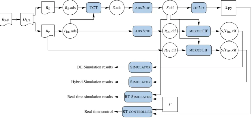
Figure3shows the developed tool framework to support the supervisory controller design. Documents, models and realizations are graphically depicted according to the convention of Figure1. (Software) tools are represented as filled, rounded rectangles.
Hybrid Simulation results
Real-time control DE Simulation results
Real-time simulation results
MERGECIF
MERGECIF
CIF2PY
SIMULATOR
SIMULATOR
RT SIMULATOR
RTCONTROLLER
TCT ADS2CIF
ADS2CIF
P PDE.ads
S.cif S.py
PDE.cif S/PDE.cif
S/PHY.cif S.ads
RS.ads RS
PHY.cif RS/P DS/P
RP
Figure 3: Tool framework based on CIF.
In the tool framework, RS/P andDS/P represent the requirements and the design of plantP under supervision of supervisorS, andRPandRSdenote the requirement documents of the plant and supervisor,
respectively. The models used in this figures are related to the models from Figure2as follows:RS.ads∈
MRS;S.ads,S.cif∈MS;PDE.ads,PDE.cif,PHY.cif∈MP; andS.py∈ZS 3.
The control requirementsRSare formally modeled by means of automata, resulting inRS.ads. Model
PDE.ads describes the uncontrolled discrete-event behavior of the plant. The TCT tool takes as input
(discrete-event) model of the uncontrolled systemPDE.ads and model of the control requirementsRS.ads.
As output, we obtain model of the supervisor S.ads. Using the ADS2CIF translator, the models of the plant and the supervisor can be translated to equivalent CIF models (PDE.cif, andS.cif, respectively). A
discrete-event model of the plant controlled by the supervisorS/PDE.cif is obtained by combining these
individual component models using theMERGECIF tool.
At this moment, the translations are implemented using the general-purpose programming language Python. Recently, we have defined the conceptual model (domain model or meta model) of the CIF lan-guage by means of Ecore class diagrams [SBPM09]. These class diagrams (see [Sys08]) will be used for the model-to-model transformations that will be developed in near future.
Using the CIF simulator (SIMULATOR), theS/PDE.cif model can be simulated to analyse its behavior
with respect to the control requirements. After that, the discrete-event model of the plant can be replaced by the hybrid CIF model of the plantPHY.cif. The next step is to replace the hybrid CIF model of the
plant by actual hardware of the plantP. The real-time simulator (RT SIMULATOR) connects the hardware of the plant and the CIF model of the supervisor to analyse the response of the plant hardware as well as the simulation output. After that, using theCIF2PYcompiler, the CIF model of the supervisor can be compiled into Python codeS.py that can be executed on real-time control platform RT CONTROLthat is connected to the actual hardware of the plant.
3 The (file) extension ‘.ads’ refers to the input language for the controller synthesis software package TCT, extention ‘.cif’ refers
4
Case study: Patient Support System
An MRI scanner, see Figure4, is used in medial diagnosis to render pictures of the inside of a patient non-invasively. To position a patient in an MRI scanner, a patient support system, consisting of a patient table (see Figure5), a user interface and a light-visor is used.
User Interface Light Visor
Bore
Patient table
Figure 4: MRI scanner
Position encoder
(on/off)
Horizontal motor
(in/out/stopped)
Clutch
(on/off)
Tabletop sensor
(on/off)
Max out sensor
(on/off)
TTR button
(on/off)
Vertical motor
(up/down/stopped)
Max up sensor
(on/off)
Max down sensor
(on/off)
Emergency
(on/off)
2×Timer
(on/off)
Figure 5: Patient table
The patient support system can be divided into the following components: vertical axis, horizontal axis and user interface. The vertical axis consists of a lift with appropriate motor drive and end-sensors. The horizontal axis contains a removable tabletop which can be moved in and out of the bore, either by hand or by means of a motor drive depending on the state of the clutch. It contains sensors to detect the presence of the tabletop, and the position of the tabletop. Furthermore, the system is equipped with hardware a safety system (emergency stop and tabletop release), that allows the operator to override the control system in emergency situations. Finally, the system contains a light-visor for marking the scan plane, and automated positioning of this scan plane to the center of the bore of the MRI scanner.
4.1
Controller synthesis
4.1.1 Models of the uncontrolled plant
The model of the uncontrolled plant consists of 5 components: 1)vertical axisconsisting of the motor model, the sensors model, and the model of the relation between the motor and the sensors; 2)horizontal axisconsisting of separate models for the motor, clutch, sensor, TTR sensor, TT sensor, encoder, and the TTS mode, respectively, and a model for the relation between the actuators and the sensors; 3)PICU consisting of models for the tumble switch, manual button, light-visor button, TTS button, manual LED, TTS LED, and the emergency LED, respectively. Furthermore, it contains a model to describe the time-behavior of the tumble timer; 4)light visor; 5)emergency subsystem. The complete models of the vertical axis are shown in Figure64.
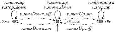
The vertical axis contains two sensors: maximally up and maximally down. Initially the table is as-sumed to be neither up or down, so that both end sensors are inactive. The sensors emit the events v max. . . onorv max. . . off, when a sensor becomes active or ceases to be active, respectively (Fig.6a). Because of the physical location, the sensors are never active at the same time.
The motor is initially in an error state (Fig.6c). The motor returns to this state after each error. From the error state, the system can be reset, to enter the inactive state. If the system is inactive, movement can be started. When movement is stopped, the system enters the stopping state. If the system is not moving anymore, the motor emits the eventstopped, and the motor enters the stopped state. From this state, either movement can be started, or the system can be reset to enter the inactive state.
VMIDDLE VUP VDOWN
v maxUp on
v maxUp off v maxDown on
v maxDown off
(a) sensor model
VSTOPPED VMUP VMDOWN
v move up
v move down
v move down v move up
v stopped v error v stopped v error v stopped v error
v stop up v stop down
v maxDown off v maxUp on v maxDown on
v maxUp off
(b) motor sensor relation model
VERROR
VINACTIVE
VMOVING VSTOPPED
v reset v err or v mo ve up v mo ve down v error vstop up vstop down vstop tumble vstop TTR v err or v stopped v error
v move up v move down
vreset
(c) motor model
Figure 6: Plant model of the vertical axis (∈PDE.ads).
VMIDDLE VUP VDOWN
v maxUp on
v maxUp off v maxDown on
v maxDown off
v move down v stop up v move up
v move down v move up
v stop down
Figure 7: Example vertical control requirements (∈SR.ads).
The sensors do not change state when the motor is not moving (Fig.6b). Only when the vertical motor is moving up, the maximally down sensor can turnoff and the maximally up sensor can turn on, and likewise for the opposite direction. Note that this model is not a control requirement, it is an physical property of the system. If this model would be included as control requirement, the resulting supervisor would be empty due to restrictions on the uncontrollable sensor events, which cannot be realized by any supervisor. Summarized, the model of the uncontrolled plant consists of 27 relatively small, loosely coupled automata.
4.1.2 Models of the requirements
In total there are 57 automata describing the control requirements for the supervisor. The automaton model of the requirement “The vertical axis should not move beyond its maximally up and maximally down position” is shown in Figure7. When the table is maximally up or down, it should stop (eventsv stop up andv stop down). In the maximally up position it is not allowed to move up (no eventv move up), in the maximally down position it is not allowed to move down (no eventv move down).
4.1.3 Synthesis of the supervisor
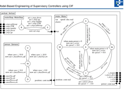
E I M S Sd act v reset when main-po wer = 0 no w act v err or act v mo ve up do speed := 5. 0 act v mo ve down do speed :=−
5.0 act
stop
dospeed
,t:=
0.0, 0.0
when main-power = 0 now actv error
dospeed:=0.0
when t≥ 0. 1 no w act v stopped when main-po wer = 0 no w act v err or
actv move up
dospeed:=5.0
actv move down
dospeed:=−5.0
act
vreset
when main-power = 0 now actv error
dospeed:=0.0 motor: Motor
var speed: disc real clock t
v error v reset v move up v move down v stopped stop
power: cont real position: cont real
M U
D
whenvpos≥10.0 now actv maxUp on
whenvpos≤0.0 now actv maxDown on
whenvpos>0.0 now actv maxDown off
whenvpos<10.0 now actv maxDown off
sensor: Sensors
v maxDown on v maxDown off v maxUp on v maxUp off
position: cont real
R S
actv stop down
actv stop up
actv stop tumble
actv stop TTR
actv stop tabletop
now actstop
motorStop: MotorStop
v stop up v stop down v stop tumble v stop TTR v stop tabletop
stop
vertical: Vertical
Figure 8: Hybrid CIF model of the vertical axis (∈PHY.cif).
4.2
Simulation of the supervisor and a hybrid model of the plant
Figure8shows the hybrid CIF model of the vertical axis component. In this figure, an automaton instan-tiation is represented as a solid box that is labeled with its name and the name of the automaton definition. Its internal declarations are listed in the upper left corner, and its external declarations are represented as ports on the borders of the box. The shape of a port depends on the type of declaration: a solid box denotes an action, and a solid triangle on the outer side (inner side) denotes an output (input) variable. Modes are visualized by means of circles labeled with the name of the mode. The flow, invariant and time-can-progress predicates are omitted from the figure, the predicates are true unless stated differently. Edges are represented as arrows between modes and are labeled with their guard, action, update (e.g. assignment to a variable), and, if the edge is urgent, the keywordnow.
The CIF model of the vertical axis consists of an automata instantiationverticalthat instantiates automa-ton definitionVertical. Automaton definitionVerticalconsists of the automata instantiationsmotorStop,
motor, andsensorthat instantiate the automata definitionsMotorStop,Motor, andSensor, respectively. Automaton definitionMotorStoptranslates the various stop events from the supervisor to a singlestop event;Motormodels the dynamic behavior of the motor; andSensorsmodels the behavior of the sensors. The invariant predicate for all modes of theMotorautomaton equalspostion˙ =speed, whereposition˙ de-notes the derivative of theposition. The automataMotorandMotorStopsynchronize on thestopevent. The automataMotorandSensorsshare the continuous variableposition.
0 2 4 6 8 10
0 2 4 6 8 10 12
-1.5 -1 -0.5 0 0.5 1
position angle
t
H_position(t) V_position(t) Tumble_angle(t)
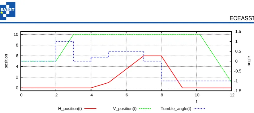
Figure 9: Simulation resultsS/PHY.cif.
4.3
Real-time, simulation based control
The sensors and actuators of the actual patient support table are connected to an industrial grade I/O controller, which in turn is connected to a standard PC. The I/O controller conditions the sensor signals, translates sensor state changes to events, and translates events from the PC to appropriate inputs for the actuators. On the PC, the events from the I/O controller are buffered in an event queue. After receiving an event from the I/O controller, the state of the supervisor is updated, and the set of controllable events that is allowed by the supervisor is calculated. From this set, an event is selected and sent to the I/O controller. In the simulation model, the plant model and the model of the supervisor interact synchronously, i.e. they synchronize on common events. However, during the Real-time, simulation based control, the interaction between the patient table and the supervisor is asynchronously. More precisely: after a change of state of a sensor, this change has to be detected by the I/O controller (sensor polling delay). Then the I/O controller sends an event to the PC (communication delay between I/O controller and PC). After detection of the event (event queue polling delay), the state of the supervisor is updated, the allowed events are calculated, and an event is selected (calculation delay). In the setup, first all events from the event queue are processed. Then, when the event queue is empty, an allowed controllable event is selected and sent to the I/O controller.
5
Conclusions
In this paper, we developed a framework for supervisory controller design, based on the Model-Based Engineering and Supervisory Control Theory paradigms. This framework enables 1) simulation of the discrete-event plant models controlled by the synthesized supervisor model in order to validate the con-trolled behavior; 2) simulation of more detailed, e.g. timed or hybrid, plant models; 3) early integration and testing by means of real-time simulation; and 4) code-generation for the supervisory controller.
To support the design process of industrial-size supervisory controllers, a tool framework, based on the Common Interchange Formalism for hybrid systems (CIF) has been developed.
As part of the MULTIFORM project, the relations between the discrete-event model of the plant that is used for the supervisory controller synthesis and the more detailed timed and/or hybrid models of the plant will be studied.
Acknowledgements: The authors like to thank Dennis Hendriks and Albert Hofkamp for implementing
major parts of the CIF tool framework, and Peter Thijs for implementing theADS2CIFtranslation tool.
Bibliography
[BRRS07] D. A. v. Beek, M. A. Reniers, J. E. Rooda, R. R. H. Schiffelers. Revised hybrid system inter-change format. Technical report HYCON Deliverable D3.6.3, HYCON NoE, 2007.
[BRRS08] D. A. v. Beek, M. A. Reniers, J. E. Rooda, R. R. H. Schiffelers. Concrete syntax and semantics of the compositional interchange format for hybrid systems. In17th Triennial World Congress of the International Federation of Automatic Control. Pp. 7979–7986. Seoul, Korea, 2008.
[BRSR07] D. A. v. Beek, M. A. Reniers, R. R. H. Schiffelers, J. E. Rooda. Foundations of an Inter-change Format for Hybrid Systems. In Bemporad et al. (eds.),Hybrid Systems: Computation and Control, 10th International Workshop. Lecture Notes in Computer Science 4416, pp. 587– 600. Springer-Verlag, Pisa, 2007.
[CL07] C. G. Cassandras, S. Lafortune.Introduction to Discrete Event Systems. Springer, 2nd edition, 2007.
[HYC05] HYCON Network of Excellence. http://www.ist-hycon.org/. 2005.
[MoB02] MoBIES team. HSIF Semantics. Technical report, University of Pennsylvania, 2002. internal document.
[MUL08] MULTIFORM consortium. Integrated Multi-formalism Tool Support for the Design of net-worked Embedded Control Systems MULTIFORM. http://www.multiform.bci.tu-dortmund.de, 2008.
[Ogr00] I. Ogren. On the principles for model-based systems engineering.Systems Engineering3(1):38– 49, 2000.
[PCPS06] A. Pinto, L. P. Carloni, R. Passerone, A. L. Sangiovanni-Vincentelli. Interchange Format for Hybrid Systems: Abstract Semantics. In Hespanha and Tiwari (eds.), Hybrid Systems: Com-putation and Control, 9th International Workshop. Lecture Notes in Computer Science 3927, pp. 491–506. Springer-Verlag, Santa Barbara, 2006.
[PFC89] R. J. Patton, P. M. Frank, R. N. Clarke (eds.).Fault diagnosis in dynamic systems: theory and application. Prentice-Hall, Inc., 1989.
[Plo04] G. D. Plotkin. A structural approach to operational semantics.Journal of Logic and Algebraic Programming60-61:17–139, 2004.
[SBPM09] D. Steinberg, F. Budinsky, M. Paternostro, E. Merks. EMF Eclipse Modeling Framework. Addison-Wesley, 2009.
[SSB+09] C. Sonntag, R. R. H. Schiffelers, D. A. v. Beek, J. E. Rooda, S. Engell. Modeling and Simula-tion using the ComposiSimula-tional Interchange Format for Hybrid Systems. In Troch and Breitenecker (eds.),6th International Conference on Mathematical Modelling. Vienna, Austria, 2009.
[SSRH08] R. Su, J. H. van Schuppen, J. E. Rooda, A. T. Hofkamp. Nonconflict Check by Using Sequen-tial Automaton Abstractions. Technical report 2008-010, Eindhoven University of Technology, 2008.
http://se.wtb.tue.nl/sereports
[Sys08] Systems Engineering Group TU/e. CIF toolset. http://se.wtb.tue.nl/sewiki/cif, 2008.
[Won07] W. Wonham.Supervisory control of discrete-event systems. Dept. Elect. Comput. Eng., Univ. Toronto, Toronto, ON, Canada, 2007.