Volume 1 (2006)
Proceedings of the
Third International Workshop on Graph Based Tools
(GraBaTs 2006)
Generating Meta-Model-Based Freehand Editors
Mark Minas
13 pages
Guest Editors: Albert Z ¨undorf, Daniel Varr ´o
Managing Editors: Tiziana Margaria, Julia Padberg, Gabriele Taentzer
ECEASST
Generating Meta-Model-Based Freehand Editors
Mark Minas1
1[email protected],http://www.unibw.de/Mark.Minas/
Institut f¨ur Softwaretechnologie
Universit¨at der Bundeswehr M¨unchen, Germany
Abstract: Most visual languages as of today (e.g., UML) are specified using a model in a meta-model-based approach. Editors for such languages have supported structured editing as the only editing mode so far. Free-hand editing that leaves the user more freedom during editing was not supported by any editor or editor frame-work since parsing has not yet been considered for meta-model-based specifications. This paper describes the diagram editor generator framework DIAMETAthat makes
use of meta-model-based language specifications and supports free-hand as well as structured editing. For analyzing freely drawn diagrams, DIAMETAparses a graph representation of the diagram by solving a constraint satisfaction problem.
Keywords:Diagram editors, meta-modelling
1
Introduction
Each visual editor, i.e., tool for editing data structures visually, implements a certain visual lan-guage. Several approaches and tools have been proposed to specify visual languages and to generate editors from such specifications. These approaches and tools can be distinguished by the way (1) the diagram language is specified, and by the way (2) the user interacts with the editor and creates resp. edits diagrams. These distinguishing features are considered in the following:
1. Traditionally, some kind of grammar has been used to specify visual languages for editors providing free-hand as well as structured editors. Some examples areextended positional
grammarsin VLDESK[CDP05] andconstraint multiset grammarsin PENGUINS[CM95]
for free-hand editing, and hypergraph grammars in DIAGEN [Min02, Min04] for free-hand as well as structured editing. Grammars describe a language syntax by rules that are applied, starting at a certain starting symbol, to derive valid sentences of the language. Syntactically analyzing diagrams means trying to find a sequence of rule applications that derive the diagram or some representation of it. Communication between diagram editor and application requires building an abstract representation of the diagram by attribute evaluation, i.e., additional specification and evaluation efforts are necessary.
of this approach. One of them is the training of users in specifying data structure with class diagrams. On the contrary, writing grammars appears to be much more complicated. Moreover, the visual modeling languages of the Unified Modelling Language (UML) are specified by models, too. Extending such visual languages then requires to use and extend their models instead of writing grammars.
2. When considering user interaction and the way how the user can create and edit dia-grams,structured editingis usually distinguished fromfree-hand editing. Structured ed-itors offer the user some operations that transform correct diagrams into (other) correct diagrams. Free-hand editors, on the other hand, allow to arrange diagram components from a language-specific set on the screen without any restrictions. The editor has to find out whether the drawing is correct and what is its meaning. Therefore, structured editors offer more guidance to the user which may make editing easy. However, free-hand edi-tors leave more freedom to the user when she edits diagrams. Allowing for (temporarily) incorrect diagrams may make the editing process even easier.
There are many examples of grammar-based tools supporting structured editing and free-hand editing. However, all of the meta-model-based approaches offer structured editing only. We are not aware of any tool supporting free-hand editing although that editing mode would offer more freedom to the user. A recent paper has shown that analyzing the correctness of a diagram and determining its meaning based on a meta-model-based approach can be efficiently solved by transforming this task into a constraint satisfaction problem [Min06]. Based on this approach, the tool DIAMETAis described in the following. Diagram languages must be specified by models, and DIAMETAgenerates visual editors offering structured editing as well as free-hand editing
from such specifications. Generated editors, therefore, allow for easy free-hand editing and, at the same time, easy meta-model-based language specifications.
The next section describes the syntax specification with models that are class diagrams of the edited object structure. Moreover, the basic concepts of syntax analysis as described in [Min06] are outlined. Section 3 introduces the common editor architecture of each editor built using DIAMETA and the diagram analysis when editing a diagram in free-hand mode based on the
concepts presented in section 2. Section 4 presents details of the DIAMETA environment, in particular on specification and code generation. Section5concludes the paper.
2
Syntax Specification and Analysis Based on Class Diagrams
ECEASST
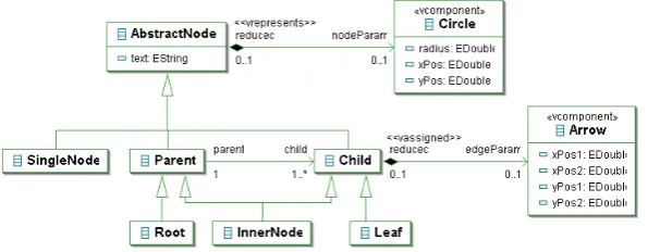
Figure 1: Model (i.e., class diagram) of trees
Class diagrams specify object structures, but they do not specify a diagram language syntax directly. Syntax specification by class diagrams is limited to those diagram languages that pro-vide a reasonably simple mapping between a diagram and its underlying object structure. This is particularly true for graph-like diagram languages that have an almost one-to-one relation be-tween diagram components and objects. DIAMETArequires that a diagram is easily and uniquely mapped to a graph that resembles its object structure.1 When drawing a diagram in free-hand mode, its representing graph is created by the editor.
We use simple trees as an example in the paper. The class diagram in Fig.1 contains class
AbstractNodeas the abstract base class of a tree’s nodes. Each node has a member attributetext2.
Concrete classes areRoot,InnerNode,Leaf, andSingleNode. Abstract superclassesParentand
Childrepresent nodes that act as parents resp. children. Please note thatInnerNodeis a subclass
of both classes. Parent-child-relations are represented by the association between Parent and
Child with the roleschild resp.parent. Please note the cardinalities; they specify that a parent
must have at least one child, and a child must have exactly one parent. The classesCircleand
Arrowrepresent aspects of the concrete syntax aspect of the visual components as described in
section3.2.
The class diagram does not completely specify trees. It does not prevent object structures from being circular, and data structures may be disconnected. The first problem could be solved by turning the association into a composite association which, by definition, prohibits circles. The second problem, however, can be described by additional constraints only. We omit them and, therefore, specify sets of trees instead of trees.
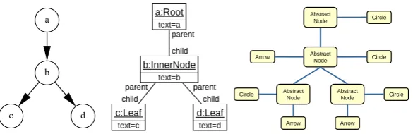
Fig.2shows a valid tree and the UML object diagram of its object structure. The node names are also used as object identifiers. Checking the represented tree for syntactic correctness means checking whether the object structure can be created by instantiation as described by the class diagram.3 That is obviously true here, i.e., the object structure and the represented diagram are
1 This process of mapping a diagram to an object structure is performed by thereduceras described in section3.4.
Since the reducer is rather powerful, DIAMETAis not restricted to graph-like diagrams, only. For instance, hierarchi-cal diagrams like statecharts are supported as well as Nassi-Shneiderman diagrams.
2 Fig.1is a screenshot of the EMF model as used in DIAMETA based on the Eclipse Modeling Framework
(EMF) [EMF06]. EMF typeEStringcorresponds to the Java typeString.
parent
child
parent child parent
child
b a
c d
a:Root
c:Leaf d:Leaf
b:InnerNode text=a
text=b
text=c text=d
60
DiaGen - Syntax Definition with Graphs, Graph Grammars and Metamodels Mark Minas, Universität der Bundeswehr München Abstract
Node Circle
Abstract
Node Circle
Circle Abstract
Node Abstract
Node Circle
Arrow
Arrow Arrow
Figure 2: Sample tree, its object diagram with respect to Fig.1, and its instance graph.
syntactically correct. However, root node, inner node and leaves of a tree cannot be distinguished visually. Actually, each leaf node may be turned into an inner node by adding an outgoing edge to another node. Free-hand editors, therefore, cannot unchangeably bind an internal representation to the visual component. The editor rather has to reconsider this binding after each diagram modification. In the example of Fig.2, an editor can deduce from context information thatais a root node,ban inner node, andcas well asdare leaves. The editor has to perform this task by first binding the common type of all possible internal representations, i.e., classAbstractNodein the example, to each visual component. The obtained data structure (calledinstance graphin the following) is similar to object diagrams with the exception of the not yet determined concrete component types.
Correctness of the instance graph and, hence, of the diagram is checked by deducing the con-crete types and examining whether the resulting object structure fits to the class diagram. In the predecessor paper [Min06], this problem is expressed as the problem of finding a special kind of graph morphism from the instance graph to the graph schema that represents the class diagram. Searching for the concrete types of the instance graph nodes is actually aconstraint satisfaction
problem(CSP). Preprocessing of this CSP requires linear time in the size of the analyzed
dia-gram. Experiments had shown that backtracking was never required after preprocessing the CSP, i.e., syntax analysis is efficient when using meta-model-based syntax specifications.
3
D
IAM
ETAeditors
DIAMETA provides an environment for rapidly developing diagram editors based on
meta-modelling. Diagram editors developed using DIAMETA (such editors are called “DIAMETA
editors” in the following) always support free-hand editing. Each DIAMETAeditor is based on the same editor architecture and contains code that is specific for this editor and its diagram language. The editor architecture is described in the following whereas section4outlines how DIAMETA’s specification and code generation tool, the DIAMETADESIGNER, is used to gener-ate the specific code of an editor.
3.1 DIAMETAeditor architecture
ECEASST
54
DiaGen - Syntax Definition with Graphs, Graph Grammars and Metamodels Mark Minas, Universität der Bundeswehr München
DiaGen: Architecture of generated editors
with Metamodels
Graph model Graph model Modeler Instance graph Instance graph Reducer Modelchecker objectsJava
Java objects Diagram Diagram Drawing tool Editor user selects operation selects operation Graph transformer (optional) reads reads ad ds/ rem oves modifies reads
Highlights syntactically correct sub-diagrams
Layouter (optional)
Figure 3: Architecture of a diagram editor based on DIAMETA.
the structure which is common to all DIAMETAeditors and which is described in the following paragraphs. Ovals are data structures, and rectangles represent functional components. Flow of information is represented by arrows. If not labeled, information flow means reading resp. creating the corresponding data structures. The structure of DIAMETAeditors is very similar to DIAGENeditors; they most prominently differ in the method of abstract syntax specification and,
hence, syntax analysis. Moreover, DIAGEN requires a specification of attribute evaluation for creating abstract diagram representations. Since class diagrams as abstract syntax specification are also a specification of abstract diagram representations, DIAMETAdoes not require such an
additional specification.
The editor supports free-hand editing by means of the included drawing tool which is part of the editor framework, but which has been adjusted by the DIAMETA DESIGNER. With this
drawing tool, the editor user can create, arrange and modify diagram components which are spe-cific to the diagram language. Editor spespe-cific program code which has been generated by the DIAMETADESIGNERfrom the language specification is responsible for the visual
representa-tion of these language specific components. The drawing tool creates the data structure of the diagram as a set of diagram components together with their attributes (position, size, etc.).
The sequence of processing steps necessary for free-hand editing starts with themodelerand ends withmodel checker(cf. Fig.3): The modeler first transforms the diagram into an internal model, thegraph model. Thereducerthen creates the diagram’sinstance graphthat is analyzed by themodel checker (cf. section2). This last processing step identifies the maximal subdia-gram which is (syntactically) correct and provides visual feedback to the user by drawing those diagram components with a certain color; errors are indicated by missing colors. However, the model checker not only checks the diagram’s abstract syntax, but also creates the object structure of the diagram’s syntactically correct subdiagram.
since wrong parts of the diagram are emphasized anyway.
Thelayoutermodifies attributes of diagram components and thus the diagram layout based on
the (syntactically correct subdiagram’s) object structure. The layouter is necessary for realizing syntax-directed editing: Structured editing operations modify the graph model by means of the
graph transformerand add or remove components to resp. from the diagram. The visual
repre-sentation of the diagram and its layout is then computed by the layouter. However, layouters and structured editing are not considered in this paper.
The processing steps necessary for free-hand editing are described in more detail in the fol-lowing.
3.2 Diagram components
Each diagram consists of a finite set of diagram components, each of which is determined by its attributes. For the diagram language of trees, there are nodes and arrows. Each node is a circle whose position is defined by itsxPosandyPoscoordinates, its size by aradiusattribute, and its inscribed text by a text attribute. Each edge is an arrow whose position is defined by its two end points, i.e., by two coordinate pairsxPos1and yPos1resp. xPos2and yPos2. All of these attributes are necessary for completely determining a diagram component, e.g., when storing it to a file or retrieving it again. However, only some of these attributes are essential for a diagram’s abstract syntax, too. In the tree example, only the inscribed text of a node is part of the abstract syntax. Position and size attributes are solely member of the concrete syntax. This fact is modelled in the tree model in Fig.1, too: Attributetextis a member ofAbstractNode; the other attributes do not belong to any class of the abstract syntax. However, they are attributes of the two additional classesCircleresp. Arrow which describe the diagram components and, therefore, belong to the concrete syntax, indicated by the stereotypehhvcomponentii.4 These concrete syntax classes belong to the diagram language’s model for two reasons:
1. In order to specify all attributes in a single model, not only attributes from the abstract syn-tax are modelled in the diagram language model, but also the attributes from the concrete syntax.
2. The object structure as result of model checking is an instance of the diagram language model in terms of its class diagram. In order to contain all the information about the diagram, its concrete syntax attributes have to be represented, too. This is necessary for computing the layout based on the object structure, but also to store an object structure and to be able to retrieve the complete diagram again.
Note that a node’s attributes are spread over two classes: CircleandAbstractNode. The con-nection between both classes is indicated by an association annotated with stereotypehhvrepresentsii. The code generator of the DIAMETADESIGNER, when generating code for visual components, uses attributes of classes annotated withhhvcomponentiistereotypes and those which are con-nected by associations annotated withhhvrepresentsiistereotypes to store a visual component’s attributes.
4 DIAMETAuses the three stereotypeshhvcomponentii,hhvrepresentsii, andhhvassignediito annotate class
ECEASST
62
DiaGen - Syntax Definition with Graphs, Graph Grammars and Metamodels Mark Minas, Universität der Bundeswehr München
circle circle
circle circle
arrow
arrow arrow
from from
from at
to to
to
at at
at at
at
border
border border
border
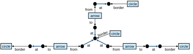
Figure 4: Graph model of the tree in Fig.2.
Note also that there is an association between classesArrowandChild that is not annotated
withhhvrepresentsii. Arrowinstances do not have a direct representative in the abstract syntax
like Circle instances that are represented by instances ofAbstractNodesubclasses. AnArrow
instance is best assigned to aChild object as it has an incoming arrow. SinceArrow instances do not have atextattribute, stereotypehhvrepresentsiidoes not make sense for the association between classesArrowandChildeither. Instead, stereotypehhvassignediiis used as annotation for this kind of associations.
Diagrams are checked for their correctness in terms of their instance graphs. The main differ-ence between instance graph and object diagram of a diagram are the not yet determined concrete classes of the object diagram. However, instance graphs are the result of a translation process from the diagram’s concrete syntax, i.e., mainly the arrangement of is diagram components. This process is described in the following, and it requires an intermediate, uniform representation of the analyzed diagram, itsgraph model.
3.3 Graph model
Arrangements of diagram components can always be described by spatial relationships between them. For that purpose, each diagram component typically has several distinctattachment areas
at which it can be connected to other diagram components. An arrow representing an edge of a tree, e.g., has its two end points as attachment areas. Connections can be established by spatially related (e.g., overlapping) attachment areas as with trees where an arrow has to end at the border of a node’s circle in order to be connected to the node.
DIAMETAuses directed graphs to describe a diagram as a set of diagram components and the relationships between attachment areas of “connected” components. Each diagram component is modeled by a node (calledcomponent node) whose type is determined by the kind of rep-resented diagram component. Attachment areas are also modeled by nodes (calledattachment
nodes). Edges (calledattachment edges) connect component nodes with attachment nodes for
all attachment areas that belong to a component. Edge labels are used to distinguish different attachment areas. Relationships between attachment areas are modeled by edges (called
rela-tionship edges) connecting the corresponding attachment nodes. Relationship edges carry the
kind of relationship as edge type.
relation-59
DiaGen - Syntax Definition with Graphs, Graph Grammars and Metamodels Mark Minas, Universität der Bundeswehr München Abstract
Node Circle
nodeParam
reduced circle
border
⇓
61
DiaGen - Syntax Definition with Graphs, Graph Grammars and Metamodels Mark Minas, Universität der Bundeswehr München
at
at from
to child
parent
edgeParam
reduced arrow
⇓
a
b
e
f c
d
a
b c
d
e
f Arrow
Figure 5: Reducer rules for trees.
ship edges. The only relationship typeatindicates that the end point of the corresponding arrow is at the border of the connected circle.
3.4 Instance graph
Thereduceris responsible for translating the graph model to the corresponding instance graph.
The translation process has to be specified in the DIAMETADESIGNERin terms of triple graph grammar rules [Sch94], calledreducer ruleshere. The rules specify the simultaneous construc-tion of the graph model as well as the instance graph. Addiconstruc-tionally, it builds up a third graph which contains the information on correspondence of nodes of the graph model to nodes of the instance graph. Fig.5shows the two rules specifying the reducer for the diagram language of trees. Reducer rules operate on triple graphs: the graph model, the correspondence graph, and the instance graph, from left to right.
The left rule indicates that whenever a circle component node together with its attachment node and their attachment edge is added to the graph model, corresponding nodes are added to the instance graph. The added nodes represent anAbstractNodeinstance for the attachment node of the tree node, and aCircle instance for its component node. The latter models the set of those attributes of a tree node that do not belong to the abstract syntax (cf. section3.2). The added edge represents the link as an instance of the association between classesAbstractNode
andCirclein Fig.1. The right rule adds anArrownode representing the arrow attributes to the
instance graph if an arrow component is added to the graph model. Right-hand side nodeseand
f are theAbstractNodenodes that have been added by the other reducer rule already. Moreover, two edges are added to the instance graph that correspond to the two associations of theChildin Fig.1.
3.5 Model checking
ECEASST
2
DiaGen – EMF & MOF Mark Minas, Universität der Bundeswehr München
Generating diagram editors with EMF-DiaGen
Editor developer
Diagram editor DiaMeta
editor framework
DiaMeta Designer
DiaMeta Designer DiaMeta
Generated program
code Editor Specification
Generated program
code
EMF Compiler
EMF Compiler
operates
EMF Model
EMF Modeller
EMF Modeller
op erate
s
Figure 6: Generating diagram editors with DIAMETA.
structure of Java objects is an abstract representation of the diagram that can be used when inte-grating the editor in a larger environment. The subgraph, moreover, corresponds to a subgraph of the graph model and, hence, a subset of diagram components that form a syntactically cor-rect subdiagram. Based on this information, feedback to the user is provided as described in section3.1.
4
D
IAM
ETAEnvironment
This section completes the description of DIAMETA and outlines its environment supporting
specification and code generation of diagram editors that are tailored to specific diagram lan-guages. The DIAMETAenvironment shown in Fig.6 consists of an editor framework and the DIAMETADESIGNER. The framework is an extension of the DIAGENframework and, as a
col-lection of Java classes, provides the generic editor functionality which is necessary for editing and analyzing diagrams. In order to create an editor for a specific diagram language, the editor developer has to provide two specifications: First, the abstract syntax of the diagram language in terms of its model, and second, the visual appearance of diagram components, the concrete diagram language syntax, the reducer rules and the interaction specification.
DIAMETA uses the Eclipse Modelling Framework EMF [EMF06] for specifying language models and generating their implementations. A language’s class diagram is specified as an EMF model that the editor developer creates by using the EMF modeller. Several tools are available as EMF modeller, e.g., the built-in EMF model editor in the EMF plugin for Eclipse, or EclipseUML by Omondo [Ecl05]. TheEMF compiler, being part of the EMF plugin for Eclipse, is used to create Java code that implements the model. Fig.1shows the tree class diagram as an EMF model. The EMF compiler creates Java classes (resp. interfaces) for the specified classes.
5
DiaGen – EMF & MOF Mark Minas, Universität der Bundeswehr München
Generation Process
Arrow
Circle model
other classes..
Arrow
Circle editor
other classes.. EClass
ecore
other classes..
DiaMeta Designer EMF Compiler
View & Control Model
M2 M1
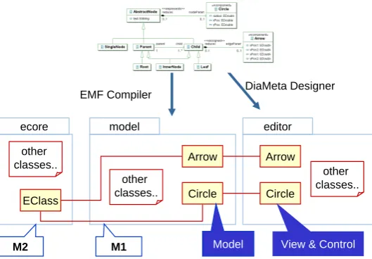
Figure 7: Generated Java classes from the specification.
inscribed name and tree edges as arrows. The DIAMETADESIGNER generates Java code from this specification. This code, together with Java code created by the EMF compiler and the editor framework, implement an editor for the specified diagram language.
Fig. 7 shows Java classes and packages that are taken from the framework resp. that are generated by the EMF compiler and the DIAMETADESIGNERfor our example of tree diagrams. The EMF compiler creates the package model5 that contains all classes corresponding to the language’s EMF model. The DIAMETA DESIGNER generates the packageeditor (or an other chosen name) together with the classes that are responsible for visualizing diagram components, interacting with them in the editor, and language specific classes for diagram analysis.
Note that two classesCircleresp. Arroware created – one in packagemodeland one in
pack-ageeditoreach. Together, they establish aModel-View-Controllerpattern of the diagram
com-ponents and the diagram: The classes in packagemodelcreated by the EMF compiler represent the model aspect whereas the classes ineditorcreated by the DIAMETA DESIGNER represent the view and controller aspects.
The classes in packagemodelimplement the EMF model and, hence, the abstract syntax of the specified diagram language. However, the EMF compiler does not only generate these classes, but also code that sets up a reflective model representation at start-up time as shown in Fig.8. The reflective model representation represents the EMF model usingEcore, EMF’s counterpart of the OMG MOF [Obj06]. This Ecore model allows to inspect the EMF model, i.e., the abstract diagram at editor runtime. In terms of the meta-modelling hierarchy, the abstract syntax of a specific diagram is on theM0 level. Its EMF model, i.e., the class diagram, is on theM1level.
Ecore is the model of all EMF models and, hence, on the M2 level. These Ecore classes of
the M2 level are instantiated at start-up time such that these instances provide a runtime data
structure representing the specified EMF model. The model checker makes use of this runtime
5 The EMF compiler actually creates several packages. To avoid cluttering of the figure, only a single package is
ECEASST
5
DiaGen – EMF & MOF Mark Minas, Universität der Bundeswehr München
Generation Process
Arrow
Circle model
other classes..
Arrow
Circle editor
other classes.. EClass
ecore other classes..
editing
Editor State editing
CSP solver
Abstract Diagram (Java object structure) uses
Model
Instances
Reflective Model Representation
at start-up
Instance Graph reducing
uses
Figure 8: Using the reflective model representation for checking the diagram’s syntax by con-straint satisfaction.
data structure in order to inspect the EMF model and to find all possible concrete classes for each node of the instance graph and all possible associations for each edge in the instance graph.
5
Conclusions
The paper has described DIAMETA, a tool for generating visual editors that support free-hand and – at the same time – structured editing. However, structured editing has not been considered in this paper. The new contribution of DIAMETA and this paper consists of the combination
of free-hand editing and a diagram language specification based on a meta-modelling approach. Earlier to this paper, meta-model-based editors had been restricted to structured editing.
The paper has described the architecture of visual editors generated by DIAMETA, and
dia-gram analysis that checks the correctness of freely drawn diadia-grams and translates them – if they are correct – into some object structure. However, there are still unsolved questions. The pre-decessor of DIAMETA, DIAGEN, that used a grammar-based syntax specification, could easily identify maximal subdiagrams that are syntactically correct; DIAMETA with its model-based syntax specification and its syntax analysis based on a constraint satisfaction problem does not yet provide as satisfying results as DIAGEN.
Moreover, DIAMETAdoes not yet support additional constraints on the object structures. Such constraints are required if the diagram language is not fully specified by a class diagram. It is planned to allow for constraint specification using OMG’s OCL and to add an OCL interpreter to DIAMETA.
automatically create Ecore instances when creating EMF models. The EMF compiler could be used without any further efforts for immediately generating code from such models.
Since EMF is a rather restricted meta-modelling framework, current work investigates OMG’s MOF 2.0 as an alternative and the MOFLON plugin [Ame04] for the Fujaba tool [NZ00]. Using MOF instead of EMF has the further benefit that the visual languages of the UML are already specified by a MOF model. Hence, generating editors for those languages will become easier. Essentially, only the concrete syntax and the reducer rules have to be specified.
Bibliography
[Ame04] C. Amelunxen. A MOF 2.0 Editor as Plugin for FUJABA. In Giese et al. (eds.),Proc.
2nd International Fujaba Days. Volume tr-ri-04-253, pp. 43–48. 2004.
[CDP05] G. Costagliola, V. Deufemia, G. Polese. Towards Syntax-Aware Editors for Visual Languages.Electronic Notes in Theoretical Computer Science127(4):107–125, Apr. 2005. Proc. Workshop on Visual Languages and Formal Methods (VLFM 2004).
[CM95] S. S. Chok, K. Marriott. Automatic Construction of User Interfaces from Constraint Multiset Grammars. InProc. 1995 IEEE Symp. on Visual Languages, Darmstadt, Ger-many. Pp. 242–249. IEEE Computer Society Press, Sept. 1995.
[Ecl05] EclipseUML on the Omondo web site. http://www.omondo.com/, 2005.
[EMF06] EMF, Eclipse Modeling Framework web page. http://www.eclipse.org/emf/, 2006.
[LVA04] J. de Lara, H. Vangheluwe, M. Alfonseca. Meta-modelling and graph grammars for multi-paradigm modelling in AToM3.Software and Systems Modelling3(3):194–209, Aug. 2004.
[Met05] MetaEdit+ documentation on the MetaCase web site. http://www.metacase.com/, 2005.
[Min02] M. Minas. Concepts and Realization of a Diagram Editor Generator Based on Hyper-graph Transformation.Science of Computer Programming44(2):157–180, 2002.
[Min04] M. Minas. VisualDiaGen – A Tool for Visually Specifying and Generating Visual Editors. In Pfaltz et al. (eds.), Applications of Graph Transformation with Industrial Relevance, Proc. 2nd Intl. Workshop AGTIVE’03, Charlottesville, USA, 2003, Revised
and Invited Papers. Lecture Notes in Computer Science 3062, pp. 398–412.
Springer-Verlag, 2004.
[Min06] M. Minas. Syntax Analysis for Diagram Editors: A Constraint Satisfaction Problem. In Celentano and Mussio (eds.), Proc. of the Working Conference on Advanced
Vi-sual Interfaces (AVI’2006), May 23-26, 2006, Venice, Italy. Pp. 167–170. ACM Press,
ECEASST
[NZ00] J. Niere, A. Z¨undorf. Using Fujaba for the Development of Production Control Sys-tems. In Nagl and Sch¨urr (eds.), Int. Workshop on Applications of Graph
Transfor-mations with Industrial Relevance (AGTIVE’99), Selected Papers. Lecture Notes in
Computer Science 1779, pp. 181–191. Springer, Mar. 2000.
[Obj06] Object Management Group. Meta Object Facility (MOF) Core Specification. Version 2.0 edition, Jan. 2006. Document - formal/06-01-01.
[Sch94] A. Sch¨urr. Specification of Graph Translators with Triple Graph Grammars. In Tin-hofer (ed.), 20th Int. Workshop on Graph-Theoretic Concepts in Computer Science. Lecture Notes in Computer Science 903, pp. 151–163. Springer Verlag, Heidelberg, 1994.
[ZGH04] N. Zhu, J. Grundy, J. Hosking. Pounamu: A Meta-Tool for Multi-View Visual Lan-guage Environment Construction. In Proc. 2004 IEEE Symposium on Visual