Proceedings of the
Third Workshop on Software Evolution
through Transformations:
Embracing the Change
(SeTra 2006)
EMF Model Refactoring based on Graph Transformation Concepts
Enrico Biermann, Karsten Ehrig, Christian K¨ohler, G¨unter Kuhns, Gabriele Taentzer, Eduard Weiss
16 pages
Guest Editors: Jean-Marie Favre, Reiko Heckel, Tom Mens
Managing Editors: Tiziana Margaria, Julia Padberg, Gabriele Taentzer
EMF Model Refactoring based on Graph Transformation Concepts
Enrico Biermann1, Karsten Ehrig2, Christian K¨ohler3, G ¨unter Kuhns1, Gabriele
Taentzer4, Eduard Weiss1
1Department of Computer Science, Technical University of Berlin, Germany,
{enrico,bunjip,eduardw}@cs.tu-berlin.de
2Department of Computer Science, University of Leicester, United Kingdom,
3Department of Software Engineering, CWI Amsterdam, The Netherlands,
4Department of Mathematics and Computer Science, Philipps-University Marburg, Germany,
Abstract:The Eclipse Modeling Framework (EMF) provides a modeling and code generation framework for Eclipse applications based on structured data models. Within model driven software development based on EMF, refactoring of EMF mod-els become a key activity. In this paper, we present an approach to define EMF model refactoring methods as transformation rules being applied in place on EMF models. Performing an EMF model refactoring, EMF transformation rules are ap-plied and can be translated to corresponding graph transformation rules, as in the graph transformation environment AGG. If the resulting EMF model is consistent, the corresponding result graph is equivalent and can be used for validating EMF model refactoring. Results on conflicts and dependencies of refactorings for exam-ple, can help the developer to decide which refactoring is most suitable for a given model and why.
Keywords:Model refactoring, Eclipse Modeling Framework, graph transformation
1
Introduction
In the world of model-driven software development, the Eclipse Modeling Framework (EMF) [EMF06] is becoming a key reference. It is a framework for describing class models and gener-ating Java code; it supports the creation, modification, storage, and loading of model instances. Moreover, it provides generators to support the editing of EMF models.
EMF unifies three important technologies: Java, XML, and UML. Regardless of which one is used to define a model, an EMF model can be considered as the common representation that subsumes the others. That means that by defining a transformation approach for EMF, it will become also applicable to the other technologies.
available, see e.g. [SPTJ01], [Por03], [MB05], which all cover at least refactoring of class mod-els. Since EMF models resemble very much UML class models, UML refactoring methods can also be considered for EMF model refactorings.
Different approaches have been considered for model refactorings, which can be categorized as model transformations in general, optimizing models of a given modeling language. Most of the refactoring approaches presented (e.g. [SPTJ01], [MB05]) use OCL constraints to describe the pre- and post-conditions of refactorings in a declarative way. Another kind of approaches use transformation rules (e.g. [Por03]). In [MT04], declarative approaches based on pre-/post-conditions are compared with graph transformation approaches.
In this paper, we consider two selected refactorings of instances of the Ecore model being the EMF meta model and as such also an EMF model. Besides the Ecore model, we could also choose any other EMF model, such as the UML2 model [UML06], for refactoring. Our transformation approach is based on graph transformation and adapted to EMF models.
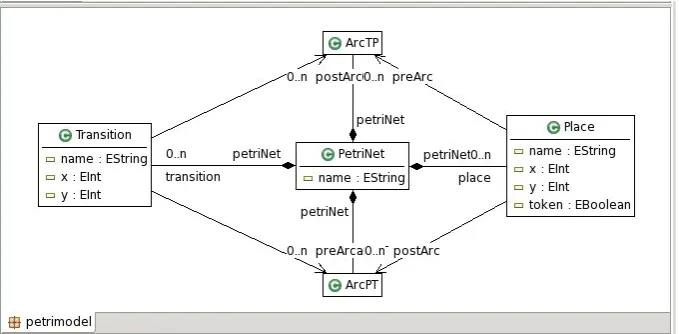
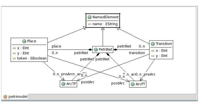
In our running example, we consider an EMF model which stores the abstract syntax of simple place/ transition Petri nets and refactor it in order to get a more object-oriented model. (See the original Petri net model in Fig.1.) This model is restructured by pulling up the common attribute ”name” of classes ”Place”, ”Transition” and ”PetriNet” to a new superclass ”NamedElement”. (See the refactored model in Fig.2.) In the following, we consider “create superclass” and “pull up attribute” as sample EMF model refactorings.
Figure 1: Petri net model before refactoring
EMF model refactoring can be considered as endogenous model transformation [MVG06] performing some kind of model optimization. When applying a refactoring method to an EMF model, this model will be modified, i.e. it will be transformed in-place. Considering the current transformation approaches for EMF such as Tefkat [LS05], ATL [JK06], MTF [MTF05], Mer-lin [Mer06], and the transformation engines developed within the Eclipse Project General Model Transformer (GMT), a transformation engine for in-place transformation and with validation facilities for model transformations is not yet available.
Figure 2: Petri net model after refactoring
transformation description can be compiled to Java code using those EMF classes already gener-ated. Furthermore, it is possible to translate the rules to AGG [AGG06], a tool environment for algebraic graph transformation where the transformation might be further analyzed.
The analysis of transformations and transformation rules is helpful in deciding what to refactor and when. Termination of refactoring operations as well as conflicts and dependencies between different refactorings are important issues to be analysed to inform the user about the refactorings which can be performed. The dependency analysis has already been considered in [MTR07].
2
Eclipse Modeling Framework
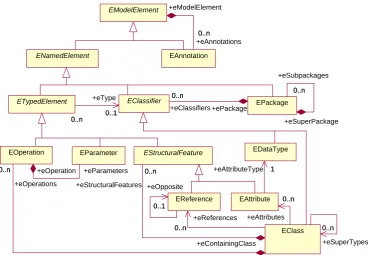
The Eclipse Modeling Framework (EMF) [EMF06] provides a modeling and code generation framework for Eclipse applications based on structured data models. The modeling approach is similar to that of MOF, actually EMF supports Essential MOF (EMOF) as part of the OMG MOF 2.0 specification [EMO06]. The type information of sets of instance models is defined in a so-called core model corresponding to metamodel in EMOF. The core or metamodel for core models is the Ecore model. It contains the model elements which are available for EMF core models in principle. In Fig.3, the main part of Ecore (without attributes) is shown. The kernel model contains elements EClass, EDataType, EAttribute and EReference. These model elements are needed to define classes by EClass, their attributes by EAttribute and interrelations by EReference. EClasses can be grouped to EPackages which might be again structured into subpackages. In addition, each model element can be annotated by EAnnotation. Furthermore, there are some abstract classes to better structure the Ecore model, such as ENamedElement, ETypedElement, etc.
ENamedElement EAnnotation EModelElement 0..n +eAnnotations 0..n +eModelElement ETypedElement EPackage 0..n +eSubpackages 0..n +eSuperPackage EParameter EClassifier 0..1 +eType 0..1 0..n +ePackage +eClassifiers 0..n EOperation 0..n +eOperation +eParameters 0..n EReference 0..1 +eOpposite 0..1 EDataType EAttribute +eAttributeType 11
EClass 0..n +eSuperTypes 0..n 0..n +eContainingClass +eOperations 0..n 0..n +eReferences 0..n 0..n +eAttributes 0..n EStructuralFeature +eContainingClass +eStructuralFeatures 0..n 0..n
File: C:\Dokumente und Einstellungen\christian\Desktop\thesis\refs\mof-vs-ecore.mdl 15:00:44 Sonntag, 25. Juni 2006 Class Diagram: Logical View / ecore-kernel Page 1
Figure 3: Kernel of Ecore model
refactoring rules and interpret these notions in terms of formal graphs and graph transformations.
3
Specification of EMF Model Refactorings
Before presenting the specification of concrete EMF model refactoring methods, we present the transformation approach used to manipulate EMF models. The transformation concepts are closely related to the algebraic graph transformation concepts [EEPT06]. The main reason for this design decision is the basic opportunity to validate EMF model transformations which is possible only if some form of consistency can be reached by the EMF transformation. We will discuss consistency issues in the next section.
3.1 EMF Model Transformation Approach
in Fig. 1) and refactor EMF instance models (e.g. Petri net instance models). Moreover a third level of refactoring could be considered: Refactoring of the ECore model itself may be possible with our approach if it is treated as dynamical class instance but the Ecore model used by Eclipse and our tool could not be refactored without adapting the Eclipse EMF packages and the related packages of our tool.
ATransformation Systemconsists of a set of transformation rules. Furthermore, it has a link to the core model its instances are typed over. Rules are expressed mainly by two object structures LHS and RHS, the left and right-hand sides of the rule. Furthermore, a rule has mappings between objects of the LHS and the RHS indicated by numbers preceding the class names. The left-hand side LHS represents the pre-conditions of the rule, while the right-hand side RHS describes the post-conditions. Those objects of the LHS which are mapped to the RHS, describe a structure part which has to occur in the EMF source model, but which is not changed during the transformation. All objects of the LHS not mapped to the RHS define the part which shall be deleted, and all symbols and links of the RHS to which nothing is mapped, define the part to be created.
The applicability of a rule can be further restricted by additional application conditions. As already mentioned above, the LHS of a rule formulates some kind of positive condition. In certain cases alsonegative application conditions(NACs) which are pre-conditions prohibiting certain object structures, are needed. If several NACs are formulated for one rule, each of them has to be fulfilled. A NAC is again an object structure which is the target of a mapping from the LHS. This feature is useful to prohibit structures connected to the LHS.
The rule’s LHS or a NAC may contain constants or variables as attribute values, but no Java expressions, in contrast to an RHS. A NAC may use the variables already used in the LHS or new variables declared as input parameters. The scope of a variable is its rule, i.e. each variable is globally known in its rule. The Java expressions occurring in the RHS, may contain any variable used within the LHS or declared as input parameter. Multiple usage of the same variable is allowed and can be used to require equality of values.
A rule-based transformation system may show two kinds of non-determinism: (1) for each rule several matches may exist, and (2) several rules may be applicable. There are techniques to restrict both kinds of choices. The choice of matches can be restricted by using input parameters. Moreover, some kind of control flow on rules can be defined by applying them in a certain order. For this purpose, rules are equipped with layers. All rules of one layer are applied as long as possible (in any order) before going over to the next layer. The transformation stops after having executed the last layer.
To apply the defined transformation rules on a given EMF model, we either select and apply the rules step-by-step, or take the whole rule set and let it apply as long as possible. A transformation step with a selected rule is defined by first finding a match of the LHS in the current instance model. A pattern is matched to a model if its structure can be found in the model such that the types and attribute values are compatible. In general, a pattern can match to different parts of a model. In this case, one of the possible matches has to be selected, either randomly or by the user.
trans-formation, more precisely a transformation sequence, consists of zero or more transformation steps.
3.2 Selected Refactoring Methods for EMF Models
Based on the presented transformation approach for EMF models we show two selected refactor-ing methods for EMF models. All transformation rules are typed over the Ecore model, in more detail over the Ecore section shown in Fig.3. In the following, we define the simple refactorings “create superclass” and “connect superclass” where a new superclass is created for a given class and can be become superclass of further classes. Moreover, the complex refactoring “pull up attribute” is shown. If each subclass contains an attribute with the same name and type, it can be pulled up to their common superclass.
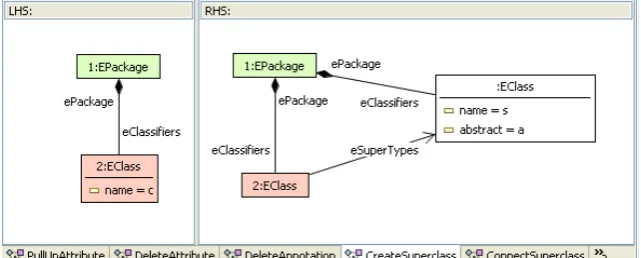
Refactoring rule “CreateSuperclass(EString c, EString s, boolean a)” in Fig.4has parameters “c” and “s” to determine the name of the child class and of the new super class. Moreover, we have to decide if the new superclass will be abstract. The LHS describes the pattern to be found for refactoring consisting of a class which will be the child and the package it belongs to. The RHS shows the new pattern after refactoring where a new class with name “s” has been created which is the superclass of the given class. The superclass will be contained in the same package as the class its subclass. Fig.4shows the left and the right-hand sides of the rule. Objects which are preserved occur in both parts. If two objects correspond to each other, they are colored and numbered equally.
Figure 4: Rule ”CreateSuperclass”
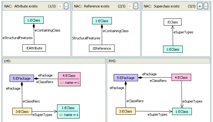
After creating a superclass, it might become superclass of more than one class which can be restructured by rule “ConnectSuperclass(EString s, EString c)” in Fig. 5. A class is allowed to become subclass of a given class, if that class does not have attributes and references yet to forbit the situation that a class or a subclass have two attributes (references) with the same name. These additional conditions are expressed by two NACs “No Attribute” and “No Reference” which check that the class does not have an EAttribute and does not have an EReference to some class.
Figure 5: Rule ”ConnectSuperclass”
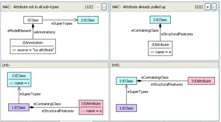
and to make the model consistent afterwards. For checking the pre-condition, rule “Check-Attribute(EString c, EString a)” in Fig.6checks for the class named “c” if there is a subclass not containing an attribute named “a”. This rule can be applied at most once, since there are NACs which check if there is already a subclass with this annotation. Thereafter, we try to apply rule “PullUpAttribute(EString c, EString a)” in Fig.7. If there is no subclass of the class named “c” which has an annotation with source ” no attribute” and if the class named “c” has not already an attribute named “a”, it looks for a subclass which has an attribute named “a”. After the refac-toring, an existing attribute with name “a” is pulled up. This rule is applicable at most once. Thereafter, NAC “Attribute already pulled up” will not be satisfied anymore. NAC “Attribute not in all sub-types” checks a necessary pre-condition.
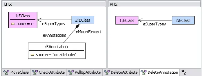
If “PullUpAttribute” was successful, i.e., there is no subclass with a corresponding annotation, all attributes named “a” being still contained in subclasses have to be deleted. This is done by rule “DeleteAttribute(EString c, EString a)” in Fig.8applying it as long as possible. Finally, if the refactoring was not successful, all new annotations have to be deleted again which is performed by rule “DeleteAnnotation()” in Fig.9. The application control for these rules just described can be realised by putting each of the rules to consecutive layers in the order of description. (See Table1.)
Figure 6: Rule ”CheckAttribute”
Figure 7: Rule ”PullUpAttribute”
creation of graph parts. We restricted our transformation approach such that for-all-conditions and -operators are supported, because we provide algebraic graph transformation as formal ba-sis for validation purposes, provided by AGG. Since there are also formal concepts for graph transformation with for-all-conditions and -operators around, it is up to future work to extend the analysis techniques for such extended graph transformation and to implement them.
Layer Rule
1 CreateSuperclass, ConnectSuperclass, CheckAttribute
2 PullUpAttribute
3 DeleteAttribute
4 DeleteAnnotation
Table 1: Control flow for refactoring “pull up attribute”
Figure 8: Rule ”DeleteAttribute”
Figure 9: Rule ”DeleteAnnotation”
“DeleteAttribute” is applied twice (to classes “Petrinet” and “Transition” in this case). Rule “CheckAttribute” does find a match, since all subclasses of “NamedElement” have attribute “name”. Similarly, rule “DeleteAnnotation” is not applicable. The result of this refactoring is shown in Fig.2.
4
Consistency of EMF Model Refactorings
Consistency of model refactorings can be understood in different ways: (1) In the software de-velopment process different kinds of artefacts such as models, programs, documentations,etc. occur. If the model is changed, the corresponding code and documentation has to be changed accordingly (see [MT04] for further information). Following the model-driven software devel-opment paradigm thoroughly, code would be changed accordingly as soon as the code generator uses the refactored model. Thus, consistency between model and code could be easily achieved in this case. (2) More basically, consistency of model refactorings should also mean a kind of syntactic correctness in the sense that the refactored model is still an element of the given mod-eling language and fulfills certain validation properties. In the following, we concentrate on this second kind of consistency, while the first kind is out of scope of this paper.
Similarly to MOF, modeling languages are defined with EMF by a class model defining the model elements and their relations. Since all refactoring rules are typed over the EMF core model, i.e. the meta model, the refactored model is still correct w.r.t. its meta model. If the meta model contains additional consistency constraints, they have to be checked after each refactoring to make sure that the resulting model is still consistent.
4.1 Consistency with Graph Transformation
To open up the possibility for formal validation of EMF model refactorings, another kind of consistency is needed. In the following, we consider EMF model refactorings as consistent if they can be compared with graph transformations. In this case, the formal analysis techniques for graph transformation become available also for EMF refactoring. Results on conflicts and dependencies of refactorings for example, can help the developer to decide which refactoring is most suitable for a given model and why.
Although EMF models show a graph-like structure and can be transformed similarly to graphs [EEPT06], there is a main difference between them. In contrast to graphs, EMF models have a distinguished tree structure which is defined by the containment relation between their classes. An EMF model should be defined such that all its classes are transitively contained in the root classes. Since an EMF model may have non-containment references in addition, the follow-ing question arises: What if a class which is transitively contained in a root class, has non-containment references to other classes not transitively contained in some root class? In this case we consider the EMF model to be inconsistent.
have to be removed, too. To ensure consistent transformations only, rules which delete objects or containment links or redirect them, have to be equipped with additional NACs.
If a containment link is deleted, the corresponding contained object has to be deleted, too. This object is not allowed to contain further objects. This constraint has to be required with a separate NAC. If a containment link is set or redirected and a maximum multiplicity is set on the container’s end, an application condition is needed which checks that this multiplicity has not yet been reached, i.e. there do not exist objects which would be without container after rule application.
Similarly to the handling of deleted structures, consistency recovery is also applied to newly created objects. If a rule creates objects which are not transitively contained in one of the root objects, the consistency recovery will remove these objects at the end of a rule application. It is easily possible to forbid the application of those rules entirely, since inconsistencies on creation of objects can be determined statically.
Our visual editor for EMF transformation rules is able to check the consistency with graph transformation discussed above. Every time an inconsistency is found, the inconsistent part is highlighted and the inconsistency is further described to inform the user.
4.2 Consistency of Selected EMF Model Refactorings
All selected refactoring rules are typed over the Ecore model, thus also the refactored EMF models will be typed over Ecore.
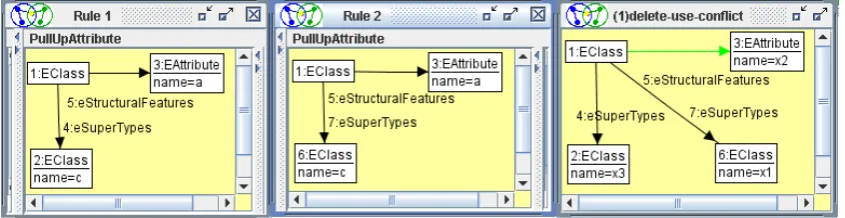
Considering the consistency of the selected EMF model refactorings, we define all objects of type “EPackage” as root objects. Now we check the consistency of those refactoring rules defined in the previous section: Rules “CreateSuperclass”, “ConnectToSuperclass”, “CheckAt-tribute”, and “PullUpAttribute” are consistent by definition. Rule “DeleteAttribute” could cause an inconsistent model in principle, but does not do so, since “EAttribute” objects cannot have children and all possible links occur in the LHS. In contrast, rule “DeleteAnnotation” defines the deletion of an object which may have children due to the Ecore model, but does not have any applying only the refactoring rules. To ensure a consistent rule application only, rule “DeleteAn-notation” could be extended by a NAC checking that there is no EObject connected to the given EAnnotation. In this way we get a set of consistent refactoring rules only which can be translated to a set of corresponding graph transformation rules for further validation. In this case, the EMF refactoring rules can be translated to AGG, a tool environment for algebraic graph transforma-tion where they might be further analyzed. Since all refactoring rules in the running example preserve the consistency of EMF models, analysis techniques such as critical pair analysis, ter-mination checks, etc. are available also for EMF model refactorings. For example in [MTR07], critical pair analysis was used to detect conflicts and dependencies between refactorings of class models.
Figure 10: Sample critical pair in AGG
5
Related Work
To realize EMF model refactoring we use an EMF model transformation environment which we have developed recently on the basis of graph transformation. There are already several model transformation tool environments around being based on graph transformation and/or Eclipse. Most of these tool environments are designed for exogenous model transformation, i.e. model transformations between different languages, and do not allow in-place model updates. This fact is one of the differences to our approach which is especially designed for endogenous model transformation, i.e. model transformation within the same language. In the following, we look a little closer to several approaches and distinguish between EMF-related and graph transformation related approaches.
5.1 EMF-Related Approaches
A rather simple approach to EMF model transformation is given by the Merlin Eclipse plug-in [Mer06] which can perform model-to-model and model-to-code transformations. Focussing on the first type of transformations type mappings and simple mapping rules consisting of con-ditions - actions pairs can be performed. Type mappings and rules are defined in a textual form.
Sub-projects in Eclipse GMT [GMT06] like Tefkat [LS05], ATL [ATL06], MTF [MTF05] and MOMENT [BCR06] support a much more elaborated transformation approach which is mainly declarative and close to the concepts of QVT, but might also allow imperative feature, as in the case of ATL. Similarly, our approach is mainly rule-based, but allows native method calls in attribute computations (as ATL does). In contrast to ours, model transformations are formulated in textual forms in all studied approaches.
Each of the QVT-related approaches considered provides a transformation engine based on EMF which might be integrated in other applications as well as a tool environment (IDE) which consists of at least an editor and a debugger provided as Eclipse plug-ins. While also offering a transformation engine and a (visual) editor, our approach lacks from an integrated debugger. For this purpose, a model transformation has to be translated to AGG where the stepwise execution of transformations is supported.
formal background. But in contrast to MOMENT our EMF transformations are based graph transformation concepts which can be used for verify properties of model transformations such as termination, confluence, and constraint checking, and can be executed by the AGG graph transformation engine.
5.2 Graph Transformation Related Approaches
There are a number of graph transformation-based approaches to model transformation, as e.g. supported by VIATRA2 [VIA06], VMTS [LLMC04], AToM3 [dLV02], GReAT [GRe06], MOFLON [MOF06], Gmorph [Sen03] and MOTMOT [Mot06]. While all dealing with graphs and their manipulation, these approaches differ heavily concerning the kind of graphs used and the transformation concepts supported. All indicated approaches support exogenous model trans-formations.
Besides standard graph transformation concepts, such as rules with left and right-hand sides and integrated attribute computations, a number of advanced transformation concepts are sup-ported. Additional forms for structuring rule sets are supported by all of the related approaches. We decided to keep our transformation model rather simple by supporting the standard transfor-mation concepts with negative application conditions for rule in addition. As advantage, graph transformations of this form can be verified based on the theory of algebraic graph transforma-tion. Additional structuring of transformation rules has to be expressed by additional Java code and is not yet taken into account for verification.
Most of these graph transformation-related approaches do not offer EMF import/export facil-ities. While VIATRA2 is able to perform EMF transformations in an interpretative mode, it is not able to generate Java code for endogenous EMF transformations. MOFLON combines MOF with graph transformation and supports the generation of JMI compliant Java code, but does not offer verification facilities.
5.3 Model Refactoring
While software refactoring has been started with the restructuring of programs, the focus of research has been extended to model refactoring recently. In [SPTJ01], [Por03], and [MB05] for example, UML class and state models are refactored using different kinds of refactoring specification languages, i.e. a script language or rule-based approaches such as QVT. While there are a number of tools such as Eclipse supporting the refactoring of class models by predefined refactoring methods, there is no tool which allows the refactoring of EMF models. Moreover, our tool envrionment allows user-defined refactoring methods for any kind of EMF model and its instances.
6
Conclusion
performed. A necessary presumption for this kind of formal validation is the consistency of EMF refactorings with graph transformations. We could show that the selected EMF model refactoring rules fulfill this kind of consistency.
It is up to future work to investigate further EMF model refactorings, to answer the following questions: How far are EMF refactorings similar to UML refactorings? Which of the EMF refactorings are consistent with graph transformation (as defined above) and thus, can be formally analysed concerning conflicts and dependencies?
Future work also includes the development of a comprehensive environment for EMF model refactoring. A visual editor and a transformation engine with code generator presented in [BEK+06] are already available at http://tfs.cs.tu-berlin.de/emftrans. Further tools such as a visual debugger and validation tools would be helpful.
Acknowledgement
This work has been partially sponsored by the project SENSORIA, IST-2005-016004.
Bibliography
[AGG06] AGG-Systemhttp:// tfs.cs.tu-berlin.de/ agg/, 2006.
[ATL06] ATL: The Atlas Transformation Language Home Page http:// www.sciences. univ-nantes.fr/ lina/ atl, 2006.
[BCR06] A. Boronat, J. Carsi, and I. Ramos. Algebraic Specification of a Model Transforma-tion Engine. InSpringer LNCS 3922. Fundamental Approaches to Software Engi-neering (FASE’06). ETAPS’06. Vienna (Austria)., 2006.
[BEK+06] E. Biermann, K. Ehrig, C. K¨ohler, G. Kuhns, G. Taentzer, and E. Weiss. Graphical Definition of In-Place Transformations in the Eclipse Modeling Framework. InProc. 9th International Conference on Model Driven Engineering Languages and Systems (MoDELS’06), Genova, Italy, October 2006.
[dLV02] J. de Lara and H. Vangheluwe. ATOM3: A Tool for Multi-Formalism Modelling and Meta-Modelling. In R. Kutsche and H. Weber, editors,Proc. Fundamental Ap-proaches to Software Engineering (FASE’02), Grenoble, April 2002, pages 174 – 188. Springer LNCS 2306, 2002.
[EEPT06] H. Ehrig, K. Ehrig, U. Prange, and G. Taentzer. Fundamentals of Algebraic Graph Transformation. EATCS Monographs in Theoretical Computer Science. Springer, 2006.
[EMF06] Eclipse Modeling Framework (EMF)http:// www.eclipse.org/ emf, 2006.
[GMT06] Eclipse Generative Modeling Tools (GMT)http:// www.eclipse.org/ gmt, 2006.
[GRe06] GReAT: Graph Rewriting And Transformation http:// www.isis.vanderbilt.edu/ Projects/ mobies/ downloads.asp, 2006.
[JK06] Fr´ed´eric Jouault and Ivan Kurtev. Transforming Models with ATL. In Satellite Events at the MoDELS 2005 Conference: MoDELS 2005 International Workshops OCLWS, MoDeVA, MARTES, AOM, MTiP, WiSME, MODAUI, NfC, MDD, WUs-CAM, Montego Bay, Jamaica, October 2-7, 2005, Revised Selected Papers, LNCS 3844, edited by Jean-Michel Bruel. Springer Berlin / Heidelberg, pages 128–138, 2006.
[LLMC04] T. Levendovszky, L. Lengyel, G. Mezei, and H. Charaf. Systematic Approach to Metamodeling Environments and Model Transformation Systems in VMTS. In2nd International Workshop on Graph Based Tools (GraBaTs), workshop at ICGT 2004, Rome, Italy, 2004.
[LS05] M. Lawley and J. Steel. Practical Declarative Model Transformation With Tefkat. In J. Bruel, editor,Satellite Events at the MoDELS 2005 Conference. Springer, LNCS 3844, 2005.
[MB05] Slavisa Markovic and Thomas Baar. Refactoring OCL annotated UML class di-agrams. In Model Driven Engineering Languages and Systems, 8th International Conference, MoDELS 2005, Montego Bay, Jamaica, Proceedings, volume 3713 of LNCS, pages 280–294. Springer, 2005.
[Mer06] Merlin Generatorhttp:// sourceforge.net/ projects/ merlingenerator/, 2006.
[MOF06] MOFLONhttp:// gforge.echtzeitsysteme.org/ projects/ moflon/, 2006.
[Mot06] MoTMoT: Model driven, Template based, Model Transformerhttp:// www.fots.ua.ac. be/ motmot/ index.php, 2006.
[MT04] Tom Mens and Tom Tourw´e. A survey of software refactoring. IEEE Transactions on Software Engineering, 30(2):126–139, February 2004.
[MTF05] IBM Model Transformation Framework http:// www.alphaworks.ibm.com/ tech/ mtf, 2005.
[MTR07] T. Mens, G. Taentzer, and O. Runge. Analysing Refactoring Dependencies Using Graph Transformation. InJournal on Software & System Modeling, 2007. To appear.
[Por03] Ivan Porres. Model Refactorings as Rule-Based Update Transformations. In Perdita Stevens, Jon Whittle, and Grady Booch, editors,UML 2003 - The Unified Modeling Language. Model Languages and Applications. 6th International Conference, San Francisco, CA, USA, October 2003, Proceedings, volume 2863 ofLNCS, pages 159– 174. Springer, 2003.
[Sen03] S. Sendall. Combining Generative and Graph Transformation Techniques for Model Transformation: An Effective Alliance? In18th Annual ACM SIGPLAN Conf. on Object-Oriented Programming, Systems, Languages, and Applications (OOPSLA), 2003.
[SPTJ01] Gerson Sunye, Damien Pollet, Yves Le Traon, and Jean-Marc Jezequel. Refac-toring UML models. In UML 2001 - The Unified Modeling Language. Modeling Languages, Concepts, and Tools: 4th International Conference, Toronto, Canada, Proceedings, volume 2185 ofLNCS, pages 134–148. Springer, 2001.
[UML06] Eclipse UML2 Project – EMF-based UML 2.0 Metamodel Implementation http:// www.uml2.org, 2006.
[VIA06] VIATRA2 (VIsual Automated model TRAnsformations) framework http: // dev.eclipse.org/ viewcvs/ indextech.cgi/∼checkout∼/ gmt-home/ subprojects/