Available online throug
ISSN 2229 – 5046
A NUMERICAL TECHNIQUE FOR SOLVING COUPLED THERMALHYDRAULIC
AND MULTI- ENERGY GROUP NEUTRON DIFFUSION EQUATIONS
S. M. Khaled
a,b,*and Fahd Al Mutairi
ca
Department of Studies and Basic Sciences, Community College, University of Tabuk, Saudi Arabia
b
Department of Mathematics, Faculty of Science, Helwan University, Cairo, Egypt
c
Department of Chemical Engineering, Faculty of Engineering, University of Tabuk, Saudi Arabia
(Received on: 30-03-14; Revised & Accepted on: 14-04-14)
ABSTRACT
A
sub-channel thermalhydraulic core analysis code CI based on the Channel Integral model is currently coupled to the three-dimensional neutronic code POWEX-K based on the neutron diffusion theory. This forms the integrated neutronic/thermalhydraulic code system POWEX-K/CI. The integrated model assessed against positive reactivity insertion transients in training and research reactors taking into account feedback effects due to coolant and fuel temperatures. An efficient and flexible cross-section generation procedure based on WIMS code was developed and included in POWEX-K/CI. The code system was then applied to analyzing power excursion accidents initiated by ramp reactivity insertions of 1.2 $. The results show that the reactor is inherently safe in case of such accidents i.e. no core melt occurs even if the safety rods do not fall into the core due to electrical, mechanical or any other reason.Key words: Gauss-Seidel iteration; reactivity accident, channel integral model, thermalhydraulic, neutron diffusion, finite difference.
1. INTRODUCTION
The safety analysis of the research and training reactors usually simulate two broad categories of severe accidents, namely, reactivity excursion accidents (the case under study in this article), and loss of coolant accidents. Usually such accidents occur when the heat produced by the reactor cannot be removed, causing overheat and melt of core components.
During these accidents the core temperatures should remain below the melting points of core components. This is important for the fuel and the clad materials. This is must be analyzed over core live, since as power distribution in the core changes due to fuel burnup or core reloading, the temperature distribution will similarly change. Furthermore since the cross sections governing the neutronics of the core are strongly temperature and density dependent, there will be a strong coupling between the thermalhydraulic and neutronic behavior of the reactor core.
The power excursion is stopped only by the feedback through the temperature coefficients (both Doppler and moderator). Consequently, the three dimensional spatial and time dependent neutronic codes with thermalhydraulic feedback calculations would be preferable to simulate reactivity induced power excursion accidents and obtaining satisfactory transient results. Unfortunately, there are no standardized computer tools or procedures for research and training reactors. These reactors require their own codes.
The objective of the present article is concerned with building this code by coupling the three dimensional dynamic code POWEX-K [1] based on neutron diffusion equations with the subchannel thermalhydraulic transient code CI based on the channel integral hydraulic model [2, 3] to form a new integrated code POWEX-K/CI for research and training core transient analysis. The finite difference method [4] has been used as a numerical technique of solving the coupled set of governing partial differential equations. The code has been tested and applied to simulate power excursion accidents initiated by ramp reactivity 1.2$ and has been compared with other experimental and theoretical methods. The results shows that the reactor is inherently safe and no overheat or melt of core components occur.
Corresponding author: S. M. Khaled
a,b,*a
Department of Studies and Basic Sciences, Community College, University of Tabuk, Saudi Arabia
2. REACTOR DESCRIPTIONS
The training and research reactor of Budapest University of Technology and Economics (BME-Reactor) is pool type reactor which is located on the site of the University. The current calculations have been done for safety analysis of the BME-Reactor. The BME-Reactor is designed to be compact and safe and it is used mainly for neutron activation analysis, production of short-lived radioisotopes and for education and training. Its maximal thermal power is 100 kW.
The reactor core is moderated and cooled by light water. The reflector is graphite surrounded by water. Other details can be found in references [5]. A summary of the design and thermalhydraulic parameters of the BME-Reactor core is given in Table 1.
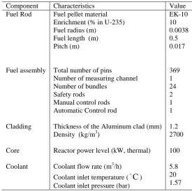
Table 1. Design parameters of the BME-Reactor core
Component Characteristics Value
Fuel Rod
Fuel assembly
Cladding
Core
Coolant
Fuel pellet material Enrichment (% in U-235) Fuel radius (m)
Fuel length (m) Pitch (m)
Total number of pins
Number of measuring channel Number of bundles
Safety rods
Manual control rods Automatic Control rod
Thickness of the Aluminum clad (mm) Density (kg/m3)
Reactor power level (kW, thermal)
Coolant flow rate (m3/h)
Coolant inlet temperature (
C
) Coolant inlet pressure (bar)EK-10 10 0.0038 0.5 0.017
369 1 24 2 1 1
1.2 2700
100
5.8 20 1.57
3. POWEX-K/CI CODE MODELS 3.1. Reactor physics model (POWEX-K)
3.1.1 Differential Equations
The BME-Reactor dynamics under transient conditions have been modeled using the neutron diffusion equations [6]:
(
(
)
(
,
)
)
(
,
)
(
1
)
(
)
(
,
)
(
,
)
)
,
(
1 T
1
∑
=
−
=
∇
∇
−
+
−
+
∂
∂
Mm
m m
m
C
t
t
t
t
t
t
r
χ
r
Φ
r
χF
r
A
Φ
r
Φ
r
D
r
Φ
V
β
λ
(1)M
m
t
C
t
t
t
C
m m m
m
1,2,...,
),
,
(
)
,
(
)
(
)
,
(
=
T−
=
∂
∂
r
r
Φ
r
F
r
β
λ
(2)
where
r
is the spatial coordinate, t is the time [sec], m is the delayed neutron family index, M is the total number ofdelayed neutron families,
Φ
(
r
,
t
)
=
[
φ
1(
r
,
t
)
φ
G(
r
,
t
)
]
T is the vector of space and time dependent neutron fluxes[n/m2/sec] and the superscript “T” denotes matrix transpose, G is the total number of energy groups,
C
m(
r
,
t
)
is the space and time dependent delayed neutron precursor concentration for delayed neutron family m [atom/m3],V
−1 is thediagonal matrix of inverse neutron velocities averaged for the energy groups [sec/m] such that
[ ]
g gg
v
1
1
=
−
V
, D isneutron fission spectrum such that
[ ]
χ
g=
χ
gp,F
is the vector of neutron production cross sections [m–1] such that[ ]
fg g
=
v
Σ
F
,χ
m is the vector of the neutron spectrum for delayed neutron precursor family m such that[ ]
χ
m g=
χ
mg,β
m is the delayed neutron fraction for family m,λ
m is the decay constant for delayed neutronprecursor family m (sec–1),
β
is the total delayed neutron fraction such that∑
=
=
M mm 1
β
β
, A is the total cross sectionplus slowing down matrix [m–1] such that:
[ ]
≠
′
Σ
−
=
′
Σ
+
Σ
=
→ ′ ′
g
g
g
g
g g
g g g
g
a R
,
A
,3.1.2 Time and Spatial Finite Difference Equations
A fully implicit (i.e. backward) finite difference approximation for time t and mesh-cell-centered formulation for spatial variable r has been used. Our iteration formula [7] reads as follows:
1
1 T T
, 1
1
1
( )
(1
)
1
M
m n m
ijk n ijk ijk ijk ijk m ijk
m
n n m
t
t
t
t
λ
λ
β
β
λ
− −
+
=
∆
=
+
+
−
−
−
∆
+ ∆
∑
Φ
V
E
A
χF
χ F
( )
( )
( )
( )
( )
( )
1, , , , 1, , , , 1,
1, , , , 1, , , , 1,
1
1 , 1
1
1
(
)
(
)
1
ijk i j k n ijk i j k n ijk i j k n
ijk i j k n ijk i j k n ijk i j k n M
m m
ijk n m ijk n
m
n n m
t
t
t
t
t
t
t
C
t
t
t
λ λ λ
λ λ λ
λ
λ
+ + +
− − −
−
− −
=
Φ
+
Φ
+
Φ
• +
Φ
+
Φ
+
Φ
+
+
∆
+ ∆
∑
R
C
S
U
H
B
χ
V
Φ
(3)
where
ijk
=
ijk+
ijk+
ijk+
ijk+
ijk+
ijkE
R
C S
U
H
B
The subscript
λ
is the iteration counter,n
is the time step and the integral of the leakage term∇
(
D
∇
Φ)
in equation (1) with respect to coordinate for group g and mesh point ijk representing coordinates x, y and z directions is approximated by the diagonal matrices Sijk, Bijk, Cijk, Hijk, Rijk, and Uijk .Also, for detailed discussion about time and spatial difference equations reader can refer back to reference[6, 7]In view of iteration formula (3) a power excursion FORTRAN program for simulating power accidents due to excess reactivity namely, POWEX-K has been built [1]. Since this program is meant for simulating reactivity accidents, the
initial fluxes
Φ
ijk(
0
)
and delayed neutron precursor concentrationsC
ijk(
0
)
att
=
0
are calculated by a staticthree-dimensional neutron diffusion code using the same group constants as the dynamic code.
As it can be seen from Equation (3) the iteration sweeps through the mesh in the sense of increasing subscripts ijk., we apply the Gauss-Seidel method. Further details about the convergence and stability of solutions will be given in the discussion.
3.2 Sub-channel thermalhydraulic module (CI)
The heat transfer model in the Channel Integral Model (CI) [2, 3] inside the fuel region is based upon one-dimensional radial heat conduction. The conservation equations are written for one-dimensional axial homogeneous upward flow through the channel. On the other hand, constitutive equations as heat transfer coefficient, friction factor are used taking into account the geometry as well as the convection regime (forced and natural). In the following, we shall discuss the basic models and equations used in both the fuel model and hydrodynamic model of CI module.
3.2.1 Thermal Heat conduction model
3.2.1.1 Differential Equations
The heat conduction equation inside the fuel element and clad was represented by the following equations [8]: v F F F pF F
q
r
T
rk
r
r
t
T
C
+
′′′
∂
∂
∂
∂
=
∂
∂
1
ρ
(4)
∂
∂
∂
∂
=
∂
∂
r
T
rk
r
r
t
T
C
C CC pC C
1
ρ
; (5)For the EK-10 type fuel pellet, there is no actual gap between the fuel outside surface and the clad, hence the accompanied set of boundary conditions
0
0=
∂
∂
= r Fr
T
and,
[
( )
( )]
co
C
C co m
r r
T
q
k
h T
t
T t
r
=∂
′′ = −
=
−
∂
Where,
q
′′
is the heat flux [W/m2],T
F(
r
,
t
)
is the fuel pellet temperature [K],T
m(
z
,
t
)
is the moderator temperature [K],T
C(
r
,
t
)
is the clad temperature [K],T
co(
z
,
t
)
is the clad surface temperature [K],ρ
FC
pF(
t
)
is the fuel pellet heat capacity [J/m3 K],ρ
CC
pC(
t
)
is the clad heat capacity [J/m3
K],
k
F(
t
)
is the fuel pellet thermal conductivity[W/mK],
q
v′′′
(
t
,
r
,
z
)
is the heat source per unit volume [W/m3],k
C(
t
)
is the clad thermal conductivity [W/mK],r
co is the clad outside radius [m],r
is the radial coordinate [m],h
is the convective heat transfer coefficient (W/m2 K).The second part of the previous boundary condition represents the coupling between the heat conduction process represented by equations (4, 5) and energy generated at the interface between the clad and the coolant through
q
′′
. The initial distributions of both fuel and clad has been taken at normal room temperatures.The thermal conductivity in [W/m K] and heat capacity in [J/kg K] for both the EK-10 fuel material type and aluminum alloy clad has been taken as functions of fuel and clad temperatures respectively [1].
Neglecting axial heat transfer and considering only radial heat transfer in transient thermal calculation of the the unit cell and applying a first order implicit finite difference formula to equation (4) and (5), the temperature at each node, at time
t
=
t
+
∆
t
is then given by the following.3.2.1.2 Finite Difference Equations
n i v n i n i fo n i ce n i ba
k
t
j
i
n
q
T
T
r
i
t
r
t
T
r
t
T
r
i
t
r
t
∆
′′′
+
=
∆
−
∆
−
∆
∆
−
+
+
∆
∆
+
∆
−
∆
+
∆
∆
−
+ + + + −)
,
,
(
)
1
(
2
1
2
)
1
(
2
1 1 2 2 1 2 1 1 2 2
α
α
α
α
α
α
(6)where n is the time index and i is the radial index, and
(
)
(
)
(
)
n i n i n i fo n i n i n i n i ce n i n i n i ba n i n iC
k
k
C
k
k
k
C
k
k
C
k
ρ
α
ρ
α
ρ
α
ρ
α
2
,
4
2
,
2
,
=
+
1=
1+
+
1=
1+
=
− + − +where
i
=
1
,
2
,...,
M
,T
in+1=
T t
i(
+ ∆
t
);
T
in=
T t
i( )
and
+
=
=
Φ
Σ
=
′′′
∑
=µ
ξ
ξ
,
i
,...,
i
j
i
n
j
i
n
q
g g v1
,
0
1
,
)
,
,
(
E
)
,
,
(
4 1 f f
(7)where
q
v′′′
(
n
,
i
,
j
)
[W/m
3]
represent the heat source per unit volume in the ith fuel radial node of the jth axial mesh, Ef
Equation (7) represents the coupling between the neutronic field represented by equations (1, 2) and the fuel heat conduction process represented by equations (4,5).
3.2.2 Hydrodynamic model
The basis of the channel integral model (CI) is an integration of the laws of conservation of mass, momentum and energy over the length of the length of the channel. During this integration, the shape of the enthalpy profile is considered to be known and invariant during the course of the transient. Consequently, by neglecting the lateral variation of the fluid properties and velocity in addition to neglecting the pressure and friction terms of the energy equation the integrated balance conservation equations of mass, momentum and energy for a single heated channel can be written as follow.
3.2.2.1 Differential Equations
The integrated balance mass, momentum, and energy conservation equations are used in the channel integral model are [3]: outlet inlet
G
G
dt
dM
−
=
(8)(
p
F
)
L
dt
G
d
−
∆
=
1
ˆ
(9))
(
outlet inlet outletH
H
G
Q
dt
dE
=
−
−
(10) Where,
∫
=
L mdz
M
0
ρ
(11)dz
G
L
G
=
∫
L m0
1
ˆ
(12)dz
H
H
E
L m(
m inlet)
0
∫
−
=
ρ
(13)dz
A
P
q
Q
L z h 0∫
′′
=
(14)∫
=
−
∂
∂
−
=
∆
Ldz
z
0
P
inletP
outletP
P
(15)∫
+
∫
+
−
=
L L me m m m m m m m
gdz
dz
D
G
G
f
G
G
F
o 0 0 2 inlet 2 outlet 22
|
|
)
/
(
ρ
ρ
φ
ρ
ρ
(16)where
∆
P
is the pressure drop andF
is the friction term.Also
A
z is the Channel flow area [m2],D
eis the Equivalent hydraulic diameter [m],f
is the Friction factor, g is the Gravitational acceleration [m/sec2],G
is the Mass flux [kg/m2 sec],H
is the Enthalpy J/kg],ρ
is the Density[kg/m3],
P
his the Heated perimeter [m], t is the Time [sec],z
is the Axial distance [m], 2 o
φ
is the Two phase friction multiplication factor,L
is the channel length [m] andP
is the pressure [M Pa].In order to perform the integrations indicated in equations (8-10), the enthalpy profile is assumed to have the same shape but not necessarily the same level as in steady state:
]
)
(
ˆ
)[
(
)
,
(
inlet inletm
z
t
H
z
H
t
H
H
=
+
β
−
(17)The function
β
(
z
)
is determined by the steady state enthalpy profile with normalization obtained by requiring that:( )
1
/
(
)
1
0
=
∫
z
L
Lβ
Applying channel integral model permits the use of pointwise conservation of mass equation to yield the following description of the mass velocity profile:
]
)
(
ˆ
)[
ˆ
,
(
)
,
(
z
t
G
inletz
H
G
t
G
inletG
=
+
γ
−
(18)Such that:
( )
1
/
(
,
ˆ
)
1
,
00
0
=
=
∫
γ
z
H
γ
L
L ,Defining
H
d
dE
C
H
d
dM
C
ˆ
,
ˆ
21
=
=
then using Equations (8, 10, 17-18) and performing integrations (11, 13) thefollowing equations has been obtained [3]:
[
Q
G
H
]
L
C
dt
H
d
∆
−
=
1
ˆ
ˆ
3
(19)
(
/
)
[
ˆ
]
)
(
ˆ
)
,
0
(
t
G
t
C
1C
3L
Q
G
H
G
=
+
γ
n−
∆
(20)Where
C
3=
(
1
/
γ
nL
)(
γ
nC
2−
(
γ
n−
1
)
C
1∆
H
)
The initial distributions at
t
=
0
of these variables are assumed to be known from the steady state solutions of the corresponding set of conservation equations (8-10).3.2.2.2 Finite Difference Equations
In channel Integral model equations (9, 19) has been solved in finite difference form yields [3]:
[
n]
m n n n
m n
m
Q
G
H
L
C
t
H
H
ˆ
)
(
ˆ
)
ˆ
(
)
(
3
1
=
+
∆
−
∆
+
(21)
[
n n]
n n
F
p
L
t
G
G
ˆ
+1=
ˆ
+
∆
∆
−
(22)
From the calculated
H
ˆ
n+1,G
ˆ
n+1 the enthalpy and mass velocity distributions can be found from the relations:[
in]
n m in
n j
m
H
z
H
H
H
)
+1=
+
(
)
(
ˆ
)
+1−
(
β
(23)[
1 1]
1
1
ˆ
)
)
ˆ
(
,
(
)
(
G
m nj+=
G
in+
γ
jz
H
m n+G
n+−
G
inn+ (24)Where j is the spatial index.
The solution is completely determined by considering the closure relationships; the initial and boundary conditions.
The initial distributions of
G
m(
z
,
t
),
and
H
m(
z
,
t
)
are assumed known from steady state solutions [2]. The heat flux)
,
(
z
t
q
′′
in a reactor is dependent on the coolant and fuel thermal conditions. Hence, the specification ofq
′′
(
z
,
t
)
is obtained from the effects of the neutronic response and the transient heat conduction in the fuel. In the present article we shall assume the inlet and outlet pressures are specified. Details about heat transfer closure relationships and Convective coolant heat transfer coefficient has been used in the current work can be found in [1].Now, Equations (1), (2), (4-5), (8-10) together with some constitutive relations for density
ρ
m and friction factorf
(or their corresponding finite difference forms) are defining completely our new integrated neutronic/tehrmalhydraulics3.2.3. Feedback process
Fuel, clad and moderator temperatures are the parameters influencing the cross sections. But why only this three parameters are taken into consideration?. Fuel temperature, moderator density, fission product poisons, and fuel burn-up are examples of feedback mechanisms that influence reactor dynamics. Feedback mechanisms are distinguished by the response time constants of order of seconds. They are hours for fission product poisons and weeks or months for fuel burn-up. Since the power excursion transient is very fast, we may assume that only the fuel and moderator temperatures (consequently the moderator density) are the significant feedback mechanisms. Consequently, only fuel, clad and moderator temperature feedback are taken into account in the current work.
Now, we shall give a brief description on how the library of group constants has been organized inside POWEX-K/CI model. When, for a given power distribution inside the core, the thermalhydraulic module computes the average fuel, clad and coolant temperatures for every mesh point of the finite difference scheme, we are able to calculate the few-group constants of the 3D diffusion equation. These few-few-group constants can be obtained by an asymptotic slowing-down and thermalisation code WIMS-D4 [9]. The thermalhydraulic feedback is taken into account via the recalculation of the few-group constants. It is needless to say that WIMS-D4 is not run in the framework of the model POWEX-K/CI but the few group constants are calculated once for ever for some selected values of the fuel, clad and coolant temperature. We thus obtain tables of the few-group constants with three entries. These tables allow interpolating the few-group constants for every particular set of these three temperatures.
4. RESULTS AND DISCUSSION
The convergence of the iteration scheme represented by equation (3) was briefly studied and proven and it was shown that the iteration is always convergent for subcritical reactor states while, for supercritical states, it is convergent only if
time step
∆
t
is sufficiently small [7]. Moreover, the method has been found unconditionally stable. Due to thebackward scheme, the time step
∆
t
is limited only by the speed of change of the neutron fluxes. Thus, relatively largetime steps may be used for slow processes. However, they should be of the order of milliseconds for power excursion accidents. It was equally shown that the Gauss-Seidel method accelerates the iteration model; too, just as it does in case of the conventional source iteration schemes. Simply, a simplified method for solving the spatial finite difference equations which avoids the usual source iteration difficulties has been built [7]. This method will be used to simulate the neutronic field in the current calculations.
In the channel integral (CI) code module, the coolant flow and the connective heat transfer problem was solved by employing the channel integral model which solves the governing mass, momentum and energy conservation equations along with the pressure balance equation for the entire domain on interest at each time step. The CI model has been found valid especially for small cores and very low coolant velocity like occurring in the BME-Reactor. The CI code can compute the flow and enthalpy distributions in nuclear fuel rod bundles and core for both steady-state and transient conditions. The CI code is very flexible for modeling a reactor core and fuel assemblies.
As a matter of fact no benchmark available for such reactor types to compare with consequently, a number of other verifications of our 3D neutronic model namely, POWEX-K has been applied experimentally [5]. As an examples of tests were applied is the following: The neutronic part POWEX-K of both integrated codes POWEX-K/MI and POWEX-K/CI has been tested experimentally [1] by a start-up experiment during which the reactor power increases exponentially but slowly. The BME-Reactor was left alone in a supercritical state with a reactivity of 14 cents and the increase of the neutron flux was observed by means of a neutron detector. The calculation has been done without thermal-hydraulic feedback due to it runs at very low power. i.e., only the neutronic part of the program i.e., POWEX-K was used. The results showed a good agreement with the experimental data. For the calculations performed for BME-Reactor, the input data used are summarized in Table 2 depending on data from reference [5].
Table 2. Channel geometry properties and operating conditions.
Operating Condition Symbol BME Units
Channel length L 0.5 m
Rod diameter D 0.01 m
Pitch P 0.017 m
Initial linear heat
q
o′
0.542 kW/mInlet mass flux
G
inlet 21.46 kg/m2 sInlet pressure
P
inlet 0.00157 MPaOutlet pressure
P
outlet 0.00150 MPaInlet enthalpy
H
inlet 84.0 kJ/kg4.1. Power Excursion at Prompt Supercriticality
The desirable excess reactivity of BME-Reactor is 1.2 $, thus, the power excursion was analyzed for the ramp insertion of this reactivity. In this case, we adjusted a reactor size for which
009432
.
1
00786
.
0
*
2
.
1
1
eff
=
+
=
k
where 0.00786 is the effective delayed neuron fraction for BME-Reactor as calculated by the kinetic version of program GRACE [10]. The adjustment was achieved by adding some fuel rods to the reactor. This is corresponds to the reality because this excess reactivity will be realized in the same way. Many previous attempts [11] have been done to simulate the current problem using the single velocity model in treating the thermalhydraulic response of the problem. In this article the thermalhydraulic response of the problem has been treated using the channel integral model [2, 3].
Figure 1 shows our new model POWEX-K/CI predictions for the total reactor power. For illustration, the results are compared with the predictions obtained by means of the REMEG point kinetic model [12] and with the 3D neutronic/thermalhydraulic model POWEX-K/MI [1]. The figure shows that, starting from 1 W, the power rises following a rapid exponential trend, increasing to 36.8 MW at 1.38 sec then it decreases due to the temperature feedbacks. While it was 28.9 MW at time 0.99 sec for POWEX-K/MI and 14.7 MW at 0.88 sec for REMEG, then it decreases after the specified times. It is remarkable that the three curves deviate from each other, namely the 3D models predicts a power peak which almost two times higher than REMEG point kinetic model. The shutdown systems would fall in the reactor within 0.5 sec, thus they could reduce the power rise. However, as mentioned before we did not assume the operation of the safety rods in order to see the effects of the inherent feedback mechanisms clearly.
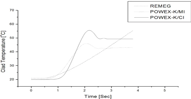
The total energy released during the transient is 23813.1 kW.sec, 23687.4 kW.sec and 8277.8 kW.sec for POWEX-K/CI, POWEX-K/MI and REMEG respectively. If we divide these numbers by the nominal power of BME-reactor, we get 3.92 min, 3.90 min and 1.4 min, respectively. This means that the energy released corresponds to the energy released during 3.92 min and 3.90 min of nominal operation for 3D models. In this basis, we do not expect very high temperatures. Figure 2 shows our model predictions for the fuel temperature while Figure 3 and 4 shows the clad and coolant temperatures at a fuel rod located near the core center and in the axial position located at half length of the fuel pin. The fuel temperature goes up to 837 oC, 681 oC and 454 oC according to POWEX-K/CI, POWEX-K/MI and REMEG respectively. The clad temperature increased to 55.5 oC and 46 oC according to the 3D models, namely, POWEX-K/CI and POWEX-K/MI while only to 55.5 oC according to REMEG in 3.5 sec. These figures are much lower than the melting point of aluminum (which is 660.2 oC). The moderator temperature for both codes is still less than 21 oC as it can be noticed from Figure 4. The calculations were done up to 3.5 seconds until all the heat generated due to the transient went into the moderator and fuel and clad temperatures are stabilized while further time is required for stabilization in REMEG point kinetic code. As in case of the reactor power, the temperatures calculated using POWEX-K/MI model are higher than those calculated by REMEG.
Figure 1. Time behavior of power for ramp reactivity of 1.2 $
Figure 2. Time behavior of fuel temperature for ramp reactivity of 1.2 $
Figure 4. Time behavior of coolant temperature for ramp reactivity of 1.2 $
0.0 0.5 1.0 1.5 2.0 2.5 3.0 3.5
0
1x10¹⁴
2x10¹⁴
3x10¹⁴
4x10¹⁴
5x10¹⁴ near core center
near reflector near a water gap
Ther
m
al
F
lux
[n/
cm
2
s
ec
]
Time [sec]
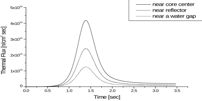
Figure 5. Thermal flux as a function of time in three different points inside the core for 1.2 $
5. CONCLUSIONS
From the results presented in the previous section, we can draw the following conclusions:
• For safety of nuclear reactors it is important to have possibility for three-dimensional neutronics calculation with good thermalhydraulic model. It gives a tool to analyze all types of accident and incident scenarios of nuclear reactor in realistic way.
• From the comparisons with the results of the point kinetic REMEG code, we may conclude that the 3D models predict the reactivity accident more severe both as far as peak powers and temperatures are concerned. This is due to the different thermalhydraulic treatments of the problem in POWEX-K/CI and POWEX-K/MI models.
• It can be noticed from Figures 2-4 that the fuel and clad temperatures during the accident are much below their melting point and no boiling will occur (i.e., single phase fluid assumption of the channel integral model is acceptable). Consequently, Even for 1.2 $ reactivity insertion, we need not reckon with the melting of the clad and boiling of the moderator.
• The 3D model predictions of temperatures are much less than the point kinetic REMEG model. This is due to the better and more sophisticated study of the problem in our new model.
• It is observable from the temperature distributions Figures (2-4) that temperatures stabilizes much faster in the 3D modeling than REMEG point kinetic model which again is an advantage of using the 3D modeling in treatment of nuclear engineering problems.
ACKNOWLEDGMENTS
The authors would like to acknowledge financial support for this work from the Deanship of Scientific Research (DSR), University of Tabuk, Tabuk, Saudi Arabia, under grant no. S-171/1434. Also the authors are indebted to Professors Attila Aszódi and Zoltán Szatmáry for their guidance and valuable help during this work. Furthermore, the authors wish to express their sincere thanks to Dr. Mujid S. Kazimi for his support.
REFERENCES
[1] Khaled S.M., "Power Excursion of The Training and Research Reactor of Budapest University", Int. J. Nuclear Energy Science and Technology, Vol. 3, No. 1, February 13, pp. 43-62, 2007.
[2] Neil E. Todreas, and Mujid S. Kazimi, Nuclear Systems II: Elements of thermalhydraulic design, Hemisphere Publishing Coordination, New York, 1990.
[3] Lee M., and Kazimi M. S., Transient response of a single heated channel, MITNE-271, July 25, 1985.
[4] Adams C.H., "Current trends in methods for neutron diffusion calculations", Nucl. Sci. Eng., 64, 552-562, 1977.
[5] Szatmáry Z., Nuclear Safety Report of BME-Training Reactor, Budapest University of Technology, Institute of Nuclear Techniques, 1996.
[6] Szatmary Z., Introduction to Reactor Physics. Hungarian Academy of Science, ISBN 9630577348, 2000. [7] Khaled S. M. and Z. Szatmáry, Numerical method for solving the three-dimensional time-dependent neutron
diffusion equation, Int. J. Nuclear Energy Science and Technology, Vol.1, 4, 2004
[8] Holman, J.P., "Heat transfer", McGraw-Hill Companies. IAEA Safety Guide on the Assessment of Research Reactors and Preparation of the safety Analysis Report, 1992. Safety Series 35-G1, 1990.
[9] Newton, T.D. and Hutton, J.I., The next generation WIMS-D4 lattice code, PHYSOR, October 7 10, Seoul, Korea, 2002.
[10] Szatmáry Z., J. Valkó, GRACE- A Multigroup Fast Neutron Spectrum Code, Central Research Institute for Physics, Budapest, KFKI-70-14-RPT, 1977.
[11] Khaled S. M., Doaa G.M., "Safety Analysis of Power Excursion Accidents for Training and Research Reactors using Different Thermalhydraulic Models", International Journal of Mathematical Archive, 2(10), 2011 pages: 1809-1818
[12] Csom Gy., Lévai F., Fehér S. and Szondi J., Development of the emergency response procedures plan for the BME-Training Reactor, Part II, Budapest, BME-NTI-178/89, 1988.