Administrator Guide
Director Software
2
Notices
© Exterity Limited 2003-2014
This document contains information that is protected by copyright. Reproduction, adaptation, or translation without prior permission is prohibited, except as under the copyright laws.
Exterity Limited, Ridge Way, Hillend Industrial Park, Dalgety Bay, Fife, KY11 9JD, Scotland, UK http://www.exterity.com
Document Reference
1300-0070-0001
Edition 6.2 Issue1 (July 2014)
Applications Described by This Guide
AvediaServer™ Channel Monitor Application AvediaServer™ Director Application AvediaServer™ Logger Application
AvediaServer™ Product Feature Manager Application AvediaServer™ System Application
AvediaServer™ TFTP Server Application AvediaServer™ Users Application
Trademarks
AvediaStream, AvediaServer, AvediaPlayer and Artio are trademarks or registered trademarks of Exterity Limited. All other trademarks are the property of their respective owners. All rights reserved.
Disclaimer
The information contained in this document is subject to change without notice.
EXTERITY LIMITED MAKES NO WARRANTY OF ANY KIND WITH REGARD TO THIS MATERIAL, INCLUDING, BUT NOT LIMITED TO, THE IMPLIED WARRANTIES OF MERCHANTABILITY AND FITNESS FOR A PARTICULAR PURPOSE. Exterity Limited shall not be liable for errors contained herein or for incidental or consequential damages in connection with the furnishing, performance, or use of this material.
Warranty
A copy of the specific warranty terms applicable to your Exterity products and replacement parts can be obtained from Exterity. To request more information or parts, email
Safety Notices
Table of Contents 3
Table of Contents
1 AvediaServer Overview... 7
2 Getting Started ... 9
Installing the AvediaServer Chassis... 9
Installing the AvediaServer on a Virtual Machine Platform... 9
Configuring the IP Address and DHCP Settings ...10
Installing AvediaServer and Artio licences ...11
3 AvediaServer Applications and Documentation ...12
4 Management Interfaces...15
Web Management Interface ...15
Admin Interface...17
5 Using the Channel Monitor Application...19
Channel Monitor Page Layout and Functions ...20
Managing Channels ...23
6 Using the Director Application...25
Getting Started ...26
Viewing Devices ...28
Managing Devices ...34
Maintenance Tasks ...34
Configuration Tasks...42
Receiver Operational Tasks...46
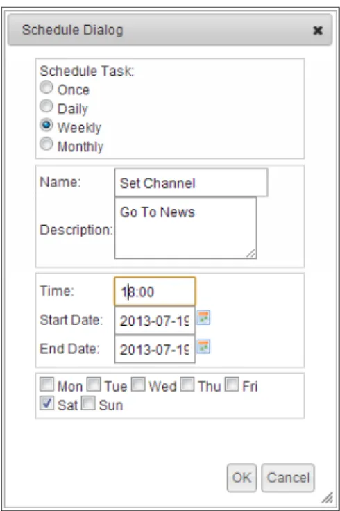
Scheduling Tasks...51
Creating Scheduled Tasks ...52
Managing Scheduled Tasks...59
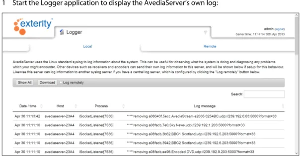
7 Using the Logger Application...62
Viewing Logging Information ...62
Logging Information to an External Syslog Server ...64
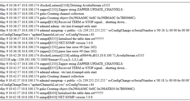
Using the AvediaServer as a Syslog Server ...65
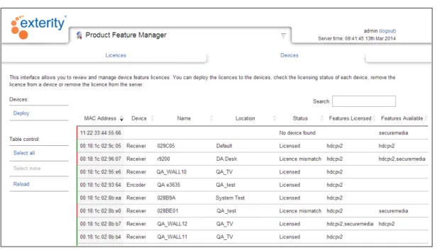
8 Using the Product Feature Manager Application...67
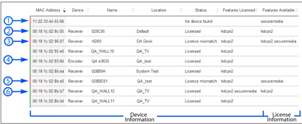
Reviewing the License Status of the IPTV Network Devices ...68
Importing Licenses to the Product Feature Manager...69
Deploying Features to Specific Devices...71
9 Using the System Application ...73
Naming the AvediaServer...74
Configuring the SNMP Community Strings ...75
Configuring Network Settings ...75
Table of Contents 4
Configuring the AvediaServer Timezone ...78
Specifying a Fully Qualified Domain Name ...80
Configuring AvediaServer Services ...81
Managing AvediaServer and Artio Licenses ...84
Status Monitoring ...86
Monitoring Content Bandwidth ...92
Maintaining the AvediaServer...93
10 Using the TFTP Server Application...98
Managing Files on the TFTP Server ...98
11 Using the Users Application ... 103
Changing the Admin Account... 104
Managing Profiles ... 105
Managing User Accounts ... 109
Configuring LDAP Access... 111
Managing AvediaServer Access Control... 116
Specifying Default Content Sharing Permissions... 119
Configuring for Secure Server Access... 121
Configuring for Single Sign-on Operation... 123
5
Glossary
The following terms and definitions are used in this document:
Table 1
DHCP Dynamic Host Configuration Protocol, a protocol used to allocate IP addresses to devices on an IP network.
EIT Found in a Transport Stream, the Event Information Table provides information to enable construction of Program Guides
EPG Electronic Program Guide FTP File Transfer Protocol
IGMP Internet Group Management Protocol, a protocol used to manage multicast traffic on an IP network.
LDAP Lightweight Directory Access Protocol
NTP Network Time Protocol, a protocol for synchronizing the clocks of computer systems. PMS Property Management System
RTSP Real Time Streaming Protocol
SAP Session Announcement Protocol, a protocol used to advertise the presence of multicast sessions on an IP network.
SNMP Simple Network Administration Protocol SSH Secure Shell
TFTP Trivial File Transfer Protocol, a simple file transfer protocol used on IP networks. VoD Video on Demand
This section contains information on the following:
• An overview of the AvediaServer Software and Applications • Basic configuration of the AvediaServer Software and Applications • An overview of the AvediaServer Administrator’s Guides
7
1
The applications displayed on the AvediaServer desktop are determined by the licensed
configuration. Table 2 lists the applications. Table 3 lists the application icons and their functions.
Table 2 AvediaServer Software and Applications
AvediaServer Director Software AvediaServer Producer Software AvediaServer Creator Software Additional Optional Applications Manage the AvediaServer settings, user access to content and applications, and monitor/manage the operation of your IPTV system and its devices.
In addition to all the functions of the Director Software, the Producer enables configuration of end-user interaction with the IPTV system, providing creation and management of multiple portals, messaging, program guides, and a web server.
Configure content encryption and property management systems (PMS) by adding the SecureMedia Link and PMS Link
applications.
In addition to all the functions of the Director and the Producer Software, the Creator allows creation and
management of recordings and their distribution/ availability.
Configure content encryption and property management systems (PMS) by adding the SecureMedia Link and PMS Link applications.
These applications must be ordered separately. Their operation is described in the AvediaServer Producer Software - Administrator’s Guide and AvediaServer Creator Software - Administrator’s Guide
Channel Monitor Artio Configurator Asset Editor Artio Multiview Configurator
Director Artio Desktop Asset Manager PMS Link
Logger Artio Desktop Manager Play SecureMedia Link
Product Feature Manager
Channel Announcer Recorder
System EPG Server Transfer
TFTP Server Macro Builder Video On Demand Users Macro Triggers
Messaging Web Server
(Plus Director Software Applications)
(Plus Director and Producer Software Applications)
8 Table 3 Application Icons and Function
AvediaServer Applications
Artio Configurator Artio Desktop Artio Desktop manager Artio Multiview Configurator
Create and manage Artio portals
Select and Play channels and on demand content on a PC or Mac
Monitor and manage Artio Desktop usage and activity
Create and display multiple channels in a tiled layout on a PC
Asset Editor Asset Manager Channel Announcer Channel Monitor
Preview and clip any listed unencrypted asset or recording
Import/Download and configure all stored content
Create SAP announcements for channels created by 3rd party streaming devices
Monitor the status of some or all the IPTV channels on the network
Director EPG Server Logger Macro Builder
Monitor and manage head end devices, AvediaServers and receivers
Collect and manage the channel data used to display Program Guides on client devices
Specify and record system information for performance and event monitoring
Create actions to be performed on devices by specified triggers
Macro Triggers Messaging Play PMS Link
Configure triggers and specify the macro to be applied in response to the trigger event
Set up configurable messages to be displayed on specified devices
Stream content on custom channels
Configure the Server for operation with a Property Management System (PMS)
Product Feature Manager Recorder SecureMedia Link System
Manage licensed features of Exterity devices.
Create and manage recordings from network channels
Configure the server for use with SecureMedia content encryption
Monitor and manage the basic functions of the AvediaServer
TFTP Server Transfer Users Video on Demand
Store and serve files such as firmware for other IPTV devices
Configure and manage the location of assets and recorded content, specifying local and remote AvediaServers and FTP destinations
Create and manage user profiles and capabilities
Manage content for on-demand availability
Web Server
Host a third party website on the AvediaServer
Installing the AvediaServer Chassis 9
2
This section provides a brief overview of the steps required to bring the AvediaServer up to operational status. Follow the steps below before proceeding with the AvediaServer configuration using the System and Users applications.
• Installing the AvediaServer Chassis
• Installing the AvediaServer on a Virtual Machine Platform • Configuring the IP Address and DHCP Settings
• Installing AvediaServer and Artio licences
Installing the AvediaServer Chassis
From version 5.0 onwards the AvediaServer is available as a device that combines the server software with a hardware platform (and optional hard disk RAID for some platforms), and also as software only, suitable for installation on a virtual machine platform. Refer to “Installing the AvediaServer on a Virtual Machine Platform” for the minimum system requirements and the installation process.
For all AvediaServer chassis installations refer to the AvediaServer c1500 Chassis Installation Guide and carry out all the required installation steps up to and including “Chapter 4 - Switching the AvediaServer On”.
Note: Ensure that you adhere to the personal safety guidelines and warnings displayed in the AvediaServer c1500 Chassis Installation Guide.
Note: From version 5.0 onwards, the physical licence dongle from Exterity has been replaced with a soft licence. The licence file is supplied on a USB memory device with the AvediaServer. It is pre-installed on the AvediaServer hardware platform but must be installed following the AvediaServer software installation on a virtual platform.
Installing the AvediaServer on a Virtual Machine Platform
Installation on a virtual machine gives customers the freedom to use their own hardware and virtual machine with Exterity software. The AvediaServer Virtual Platform option is delivered as an ISO file on a USB memory device and is licensed for a fixed MAC address supplied by Exterity. The licence file is supplied with the AvediaServer virtual platform.
Minimum Virtual Platform Requirements
The minimum Exterity recommendation for a virtual machine equivalent is: • Intel Quad core X3430 2.40 Ghz Processor
• 2 GB RAM • 500 GB disk space Please note the following:
• Only a virtual machine install is supported, Exterity does not support simple installation on non-Exterity hardware.
• AvediaServer performance under a virtual machine cannot be guaranteed as it depends on factors such as the physical machine, virtual machine configuration parameters, and the number of other virtual machines running on the same hardware.
Configuring the IP Address and DHCP Settings 10 • Where VoD, Play or Record functions are required Exterity strongly recommends that the
AvediaServer virtual machine is the only VM running on the physical machine.
Installation Process
Exterity recommends the use of propriety software such as VMware for the installation of the AvediaServer on a virtual machine. The physical machine should meet the requirements described in “Minimum Virtual Platform Requirements”, above.
The AvediaServer software is supplied as an ISO image file on a USB stick. You must ensure that the virtual machine application is configured to allow selection and use of this file type during the installation.
Caution: The AvediaServer software only functions with the MAC address specified by the licence. When installing the AvediaServer software on a virtual machine you MUST configure its MAC address to match that of the supplied AvediaServer licence.
Note: The following procedure is generic and provides only a guide to the steps required for installation. Refer to the documentation for the virtual machine software in use. To install the AvediaServer on a virtual machine:
1 Ensure the virtual machine is correctly configured to meet the requirements specified in “Minimum Virtual Platform Requirements” on page 9 and is connected to the IP network. 2 Configure the virtual machine MAC address to match that of the AvediaServer licence supplied
by Exterity.
3 Insert the supplied AvediaServer Virtual Platform memory device into a USB port accessible from the browser/PC you are using.
4 Start the virtual machine and locate the AvediaServer software. 5 Proceed with the installation into the virtual machine environment. 6 On completion:
a. Configure a static IP address for the AvediaServer VM.
b. Log into the AvediaServer Web Interface and using the System application, install the AvediaServer and licence. Refer to “Managing AvediaServer and Artio Licenses” on page 84.
Configuring the IP Address and DHCP Settings
By default, the AvediaServer requires a DHCP Server to be available on the network to assign it an IP address. Allocating a static IP address for the AvediaServer allows continued operation without a DHCP Server.
Exterity strongly recommends using a static IP address for an AvediaServer because other Exterity devices will rely on this address remaining the same.
To assign a static IP address to the AvediaServer, temporarily set up a DHCP server on an isolated network. Once an IP address is assigned to the AvediaServer, you can configure a static IP address using the System application.
Refer to the associated virtual machine documentation to configure an AvediaServer VM installation with a static IP address.
Installing AvediaServer and Artio licences 11
Determining the DHCP assigned address
There are four methods to find out the IP address assigned via DHCP:
1 Check the leased IP address database of the DHCP server. Match the MAC address of the AvediaServer to an allocated IP address.
2 If you already have another AvediaServer (release 3.2.0 or later) in the system, click Director > AvediaStream and select AvediaServer from the Device drop-down list. All AvediaServer MAC and IP addresses are listed.
3 Connect directly to an AvediaServer RS-232 port using a null modem cable and another computer
• Baud rate: 115200 • Data: 8 bit • Stop Bit: 1 • Parity: None
4 If you cannot use any of the methods listed above, connect a keyboard, mouse and monitor directly to the AvediaServer chassis ports.
a. At the Operating System screen, log in using the username=serveradmin and
password=labrador.
b. Locate and click the Firefox icon or click Applications > Internet > Firefox to launch the browser.
c. Enter http://localhost in the browser address field to display the AvediaServer web interface.
d. Log in locally using the username=admin and password=labrador.
e. Start the System application and click the Network tab. The AvediaServer IP address information is listed.
Installing AvediaServer and Artio licences
AvediaServer Chassis/Software combinations are delivered with the purchased licences pre-installed and require no further configuration. AvediaServer VM installations require the licences to be installed following the software installation. If you are upgrading AvediaServer applications and/or bandwidth licences, adding more Artio licences, or completing an
AvediaServer VM installation, refer to the procedures described in “Managing AvediaServer and Artio Licenses” on page 84.
12
3
Documentation
The Exterity AvediaServer is a modular system both in terms of the physical hardware and the applications. To help you make best use of the AvediaServer and its applications, the following documentation is available.
Hardware
The AvediaServer Installation Guide contains all safety and regulatory information and shows you how to install the AvediaServer in a rack, power it on, and connect it to the IP network. Hard drive replacement for the c1555 chassis is also described. If you have installed AvediaServer in a virtual machine environment, refer to the documentation supplied for the platform.
Software Modules
The AvediaServer Director Software - Administrator’s Guide describes how to manage and maintain the core functions of the AvediaServer including its licensing, IP network settings, system name and location, time server, user accounts, and monitor and manage the features and operation of the IPTV system devices.
Refer to the AvediaServer Director Software - Administrator’s Guide for more information about using the Channel Monitor, Director, Logger, Product Feature Manager, System, TFTP Server, and
Users applications.
The AvediaServer Producer Software - Administrator’s Guide describes how to manage the client interfaces and deliver content, providing messaging, program guides, content encryption, middleware such as property management systems (PMS), and a web server.
Refer to the AvediaServer Producer Software - Administrator’s Guide for more information about using the Artio Configurator, Artio Desktop, Artio Desktop Manager, Channel Announcer,
EPG Server, Macro Builder, MacroTriggers, Messaging, and Web Server applications.
The AvediaServer Creator Software - Administrator’s Guide describes how to create, edit and manage recordings and configure their distribution and availability.
Refer to the AvediaServer Creator Software - Administrator’s Guide for more information about using the Asset Editor, Asset Manager, Play, Recorder, Transfer, and Video on Demand applications.
Director
Software
Producer
Software
Creator
Software
13
Non-Module Software
The SecureMedia Link, PMS Link, and Artio Multiview Configurator applications can be ordered in addition to the Producer or Creator Software modules. They are not available with the Director module.
Refer to the AvediaServer Producer Software - Administrator’s Guide or the AvediaServer Creator Software - Administrator’s Guide for more information about the SecureMedia Link, PMS Link, and
Artio Multiview Configurator applications.
Artio Configurator
The Artio Configurator is part of the Creator Software Module but has its own documentation. The Administrator’s Guide contains mainly reference material. The Artio Portal Quick Start Guide shows how to create a basic portal.
Scope
This edition of the manual refers to version 6.0 of the AvediaServer and describes the operation and use of the applications listed in “AvediaServer Software and Applications” on page 7.
Conventions
The following conventions are used in the AvediaServer Administrator’s Guides:
Note: A Note calls attention or adds information that is important for the proper operation of the product.
Caution: A CAUTION notice calls attention to an operating procedure or practice that, if not correctly performed, could result in damage to the product or loss of important data. Do not proceed beyond a CAUTION notice until the indicated conditions are fully understood and met.
Courier Font - is used to identify scripts, code examples, or keyboard commands. Emphasis is used when referring to another document, for example AvediaServer Chassis Installation Guide.
Audience
This manual is intended for use by systems integrators or systems administrators who are installing and setting up Exterity products.
It is assumed that readers are familiar with installing and configuring network-based products. Ideally, readers will also have an understanding of the key features of an IPTV system.
Copyright
The Exterity AvediaServer is a powerful product that allows you to import (copy) content (audio and video) and subsequently distribute that content to large numbers of users over an IP network. Content may have a copyright and you should always secure the permission of the copyright holder in order to copy and transmit the content on the IP network.
Unauthorised use and/or duplication of copyrighted material may be a violation of copyright law in one or many countries/regions. In using the AvediaServer you accept full responsibility for the copyright status of the content you import and transmit on the IP network.
Specialised
Applications
14
Safety
This guide refers to the AvediaServer applications only. For all Safety and Regulatory information associated with the AvediaServer chassis please refer to the AvediaServer Chassis Installation Guide located on the AvediaServer page at: www.exterity.com/support.
Web Management Interface 15
4
The AvediaServer has two management interfaces as follows: • Web Management Interface
• Admin Interface
Web Management Interface
You can manage every aspect of AvediaServer functionality using the Web Management Interface and the available applications. The Web Management Interface is optimised for Microsoft Internet Explorer and Mozilla Firefox browsers.
Figure 1 AvediaServer – Web management interface Table 4
Element Description
1 Logo and active application Displays the active application. Figure 1 shows the AvediaServer home screen with all available applications. To return to the home screen from an application, click the Exterity logo. Click the selected application name (or the down arrow) to hide the application page. This allows you to see and/or select another application from the home screen.
2
4
3
Web Management Interface 16 Open the Web Management Interface as follows:
1 Determine the IP address of the AvediaServer using the methods described in “Configuring the IP Address and DHCP Settings” on page 10.
2 Open a browser window and enter the IP address of the AvediaServer directly into the address field.
The AvediaServer login page is displayed:
Figure 2 AvediaServer login page
Note: Your browser must be configured to allow cookies. 3 The default login details are:
Username: admin Password: labrador
4 The Web Management Interface opens in your browser, as shown in Figure 2. 5 Refer to Table 4 above for interface summary information.
Note: By logging into the AvediaServer you are accepting the terms of the Exterity Licence Agreement.
The administrator can change the admin password in the Users application. For more information, refer to “Changing the Admin Account” on page 104.
2 User, Logout, and time The logged-in user name, logout function and server time are displayed. This is either 'admin' or an assigned user name. If Active Directory access has been configured the user's common name is displayed. Click logout to close the session and return to the login screen.
3 Applications All the applications enabled by the licence configuration or login profiles are displayed on the home screen.
4 System summary The System summary function displays basic information about the AvediaServer such as the IP address, serial number and configured name and location. Click the Exterity logo to return to the home screen.
Admin Interface 17
Admin Interface
In certain circumstances it may not be possible to manage the AvediaServer via the Web Management Interface. If you know the IP address of the AvediaServer, you can use a terminal application (such as PuTTY) to provide an SSH connection to the Linux kernel.
Alternatively, connect a mouse, keyboard, and VGA monitor to the AvediaServer chassis interfaces. Log into the Admin Interface using the following login details:
User name: serveradmin Password: labrador
Figure 3 Admin interface
Note: The same login credentials can be used for local access when using a directly connected monitor, keyboard and mouse.
This section contains the following: • Using the Director Application
• Using the Channel Monitor Application • Using the Logger Application
• Using the Product Feature Manager Application • Using the System Application
19
5
Application
The Channel Monitor application allows prompt and accurate monitoring of channel status. The list of network channels is built up by listening for SAP announcements from head-end equipment. Additionally, by connecting to the multicast stream of each selected channel in turn, both the presence and integrity of the transport stream encapsulation is determined. Both Multicast RTP and UDP channels are detected.
If a valid stream is not detected on a monitored channel within the specified channel aging period, the channel is highlighted red in the Channel Monitor application. Channels are highlighted yellow when they have stopped streaming but have not yet reached the full aging time limit. You can change the channel aging values on the Director application Configuration page. (Time before marking channel as off-air:)
Channel, stream and source device information is displayed in an orderable and searchable table. The table is split into the Listener (on the left) and the Monitor (on the right):
Figure 4 Channel Monitor application
Note: For channels to be added and updated automatically, the SAP (Session Announcement Protocol) must be enabled by the streaming devices (head-end), and the Channel Listener service must be running in the AvediaServer System application Services page.
The Channel Monitor function, also located on the System application Services page, must be enabled and running to enable use of the Monitor section of the channel table.
Channel Monitor Page Layout and Functions 20
Channel Monitor Page Layout and Functions
This section describes the highlighted areas of the Channel Monitor Page.
Channels and Search
The channels table and search functions allow you to remove channels from the list, turn monitoring on and off, and search within the table contents.
Figure 5 Channels listing
• Search: Entry field – orders the table by best match to text and numbers within any entry listed in the table. The list is interactively updated as you enter data into the search field.
• Headings: You can order the table by clicking on the name of any column heading. Click a column heading again to reverse the order. The order is indicated by the up/down arrows. • Channel Name, URI and Source Hyperlinks: You can quickly check the channel content by
clicking the Name or URI hyperlinks. Click the Source Name hyperlink to log in to the Web Interface of the channel source device.
Column Headings
The column headings can be used to order the entries in the table by the column heading. For example, to order the table by channel name click Name. To invert the order click Name again. The checkbox allows you to select/deselect all channels in the table.
Listener Headings
• # – Displays the channel number assigned at the stream source. The channel number is configured using the AvediaStream Encoder, TVgateway, or Transcoder Web Interfaces which are accessed using the channel Source hyperlink.
• Name – Displays the name of the channel.
• URI – Displays the channel multicast address and port number.
• Source Name – Displays the assigned name of the head-end device which is transmitting this channel.
• Source Type – Displays the type of the head-end device which is transmitting this channel, for example, Gateway.
• Groups – Displays the channel Group membership.
• Video PID – Displays the video packet ID within the channel stream, or audio only if there is no video.
• Audio PID – Displays the primary audio packet ID (PID). Only one Audio PID is listed for a channel.
• Stream ID – Displays the stream ID of the channel, containing information about its origin and content. It is in the form, originator network id:transport stream id:service id, and is applied to the stream by the originating broadcaster.
Channel Monitor Page Layout and Functions 21 • Last SAP – Displays the time elapsed since receipt of a channel Session Announcement
Protocol (SAP) message.
Monitor Headings
All Monitor parameters display n/a when the channel is not being monitored • Scrambling – Indicates if a channel is scrambled.
• Bitrate (Mbps) – The measured bit rate for the channel.
• Uptime – The length of time the channel has been streaming. The counter starts from when monitoring starts or when the channel started streaming, whichever is later. Displays n/a when the channel is not monitored or not streaming.
• Cont Err – The number of detected continuity errors.
• TEI Err – The number of transport errors. A Transport Error Indicator is raised by the
demodulation section of a device, such as a TVgateway, to indicate that it was unable to correct an error in the stream.
• Sync Err – The number of Sync errors detected.
Channel Details
Each row lists the channel details in accordance with the column headings.
Figure 6 Channel details
• Color coding – The channel listing is color coded according to the channel activity. The Channel Listener must be enabled on the System application Services page. Yellow highlighting is applied when no SAP announcements are received for over 1 minute. Red highlighting is applied after 10 minutes and indicates an inactive channel.
• Monitoring – The green timer icon is displayed in the channel row when it has been selected and monitoring enabled.
Page Control
The paging step buttons allow you to page through longer lists of channels. You can also choose how many channels to display on a single page by selecting a value from the Show drop-down list. The default number of channels per page is 10.
Figure 7 Page control
Navigate through the pages by clicking the step forward/back single arrows.
The lower line displays the range of channels from the total currently displayed. If you have filtered the results by entering text in the search field, the lower line displays the range of results from the total number of channels.
Channel Monitor Page Layout and Functions 22
Configuring Channel Monitor Settings
If a valid stream is not detected on a monitored channel within the specified channel aging period, the channel is highlighted red in the Channel Monitor application. Channels which are no longer streaming, but have not yet reached the configured off line threshold are highlighted yellow. You can change the channel aging values on the Director application Configuration page. (Time before marking channel as off-air:)
Note: Monitoring of specific channels in the Channel Monitor application is disabled by default. To configure the Channel Monitoring settings:
1 Start the Director application. 2 Click the Configuration tab.
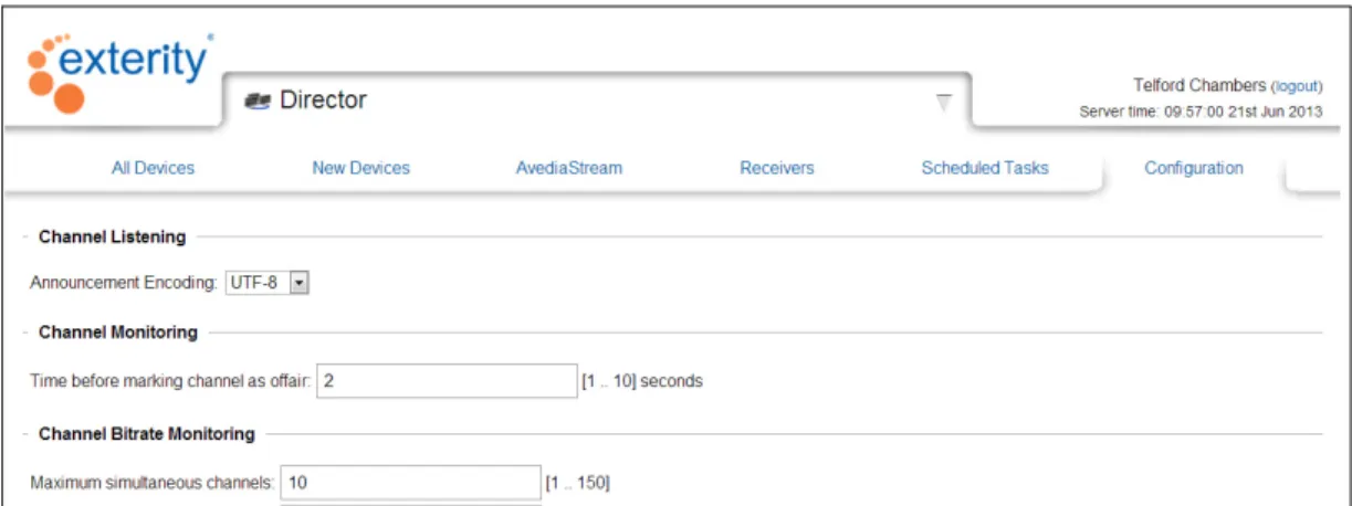
Figure 9 Director application - Channel Monitor configuration
3 Enter a value for Time before marking Channel as off-air. This specifies the time to wait for data before declaring that a channel is not streaming. The default is 2 seconds and the range 1 to 10. 4 Enter a value for the Maximum simultaneous channels the Channel Monitor application can
open. The default is 10 and the range is 1 to 150.
5 Enter a value for the Time between channel starts. Channel monitoring is performed in a sequential manner. This specifies the delay between closing one channel and opening the next. The default is 3 seconds and the range 1 to 10.
6 Enter a value for the Bit rate sampling time. This specifies the time used to determine the streaming rate of a channel. The default is 2 seconds and the range 1 to 10.
Managing Channels 23
Managing Channels
The Channel Listener function uses SAP (Session Announcement Protocol) messages to add the announced channel to the list. Channels added using the Channel Announcer application are also listed. The channel details are listed in the individual line items. Using the hyperlinks in the table you can view the channel in your browser (Artio Desktop) or open the web interface for the channel streaming device to make configuration changes if required.
Channels remain in the list, even when streaming has stopped and SAP messages are not
broadcast. Yellow highlighting is applied when the channel activity cannot be determined for over 1 minute. Red highlighting is applied after 10 minutes.
The channel aging function allows you to quickly identify non-streaming channels by highlighting them in red.
Additional channel details are provided by the Monitor function which can be enabled as required. This section shows you how to:
• Identify and delete non-streaming channels • Enable channel monitoring
• Change channel parameters
Identifying and Deleting Non-Streaming Channels
Identifying non-streaming channels allows you to see at a glance if any channels have unexpectedly stopped sending SAP announcements. Channels which are no longer being announced are highlighted red. A channel may have stopped streaming for several reasons, for example:
• It has been deliberately stopped at the head-end. • It is no longer being broadcast.
To identify and delete non-streaming channels:
1 Start the Channel Monitor application to display all channels.
2 Click Last SAP twice to list the channels by oldest SAP announcement. 3 If required, you can perform additional checks:
• Click the channel Name or URL and confirm the channel is inactive.
• Click the Source hyperlink to launch the device web management interface, log in and confirm that the device is functioning normally.
4 Click the channel to select it and click Delete to remove it from the list.
Enabling/Disabling Channel Monitoring
Channel monitoring provides additional information about a selected channel. It does not use the Channel Monitor Service, but instead opens the channel directly for examination. This can be useful in identifying for example, scrambled channels, channels with the highest bandwidth requirements and those with errors.
To enable/disable channel monitoring: 1 Start the Channel Monitor application.
2 Locate the channel you want to monitor and select it by clicking at the left end of its row in the table.
Managing Channels 24
Figure 10 Starting the Monitor 3 Click Start Monitoring.
4 Confirm the icon is displayed on the selected channel listing.
Changing Channel Parameters
Parameters such as channel name, group membership, and streaming bitrate are configured by the streaming device. However, the source device is listed for each channel and you can use this to access the device web management interface and make configuration changes if required. To change channel parameters:
1 Locate the channel of interest in the table.
2 Click the device hyperlink in the Source column. (The type of device is displayed in the Source Type column.)
3 Enter the administrator login and password to access the device’s Web Interface. 4 Refer to the Exterity AvediaStream Encoder, Transcoder, TVgateway or AvediaServer
25
6
The AvediaServer Director application is provided with all AvediaServer configurations and allows administrators, or users with administrator level access (specified by their profile), to control and manage the IPTV system from anywhere on the network.
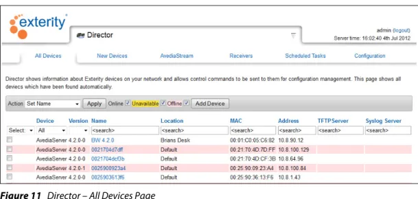
Figure 11 Director – All Devices Page
With the AvediaServer Director application you can:
View
Four views of key information (All Devices, New Devices, AvediaStream, and Receivers) are available:
• A matrix of all the Exterity devices on the network, showing details such as: • Device type
• Location • IP address
• New device view listing all Exterity devices that have been recently discovered over a configurable time interval.
• Scheduled task view showing all scheduled commands.
Monitor
• User selections (content/volume) on any receiver in the IPTV network (Receivers page only).
Control
• AvediaStream TVgateways for live broadcast TV and radio.
• AvediaStream Encoders for video from DVD/Blu-ray players and video cameras. • AvediaStream Transcoder for streamed AV transcoding.
• AvediaServer to set name, location and ping.
• AvediaPlayer Receivers for single or multiple unit control such as display of messages, channel and volume change settings.
Getting Started 26 • Task scheduling; any command that can be sent to a device can be scheduled to run at a later
date.
Note: You must be a member of the admin profile, or have the Director application access enabled in your profile to access the Director functions. Refer to the Users application section of the Managing the AvediaServer - Administrator’s Guide for more information. Access Director functions from the AvediaServer Web Management Interface homepage by clicking the Director icon and selecting the menu page as required. Figure 11 shows the Director application open at the All Devices page.
Getting Started
This section shows you how to carry out the basic configuration of the Director application. Unless specifically required, use the default settings to manage the devices and channels within the IPTV network.
Note: The Device Listener and Channel Listener services must be running on the System
application Services page to ensure devices and channels are added automatically. Ensure the Start on Boot Disable button is displayed, indicating the services are configured to start on boot.
Figure 12 Device and Channel Listener Services
Director Configuration
The Director application Configuration page allows you to specify the Channel Monitoring and Device Monitoring aging settings, and the SNMP (Simple Network Management Protocol) settings.
Figure 13 Director Application – Configuration Page
Device Monitoring
The AvediaServer Director application discovers Exterity devices by listening for device discovery messages. These discovery messages, known as keep-alive traps, are SNMP traps broadcast to UDP port 162. AvediaPlayer r92xx receivers with v2.0 firmware or later, TVgateway 4.2.11 or later, SD encoder 2.3.3 or later, and HD encoder 1.3.4 or later can unicast or multicast.
These messages are local to a subnet/VLAN. If any of the Exterity devices are on a different subnet/VLAN from the AvediaServer, you must configure the router to forward these broadcasts to the AvediaServer, or manually add the devices.
Getting Started 27 If you add the devices manually without forwarding the SNMP Multicast trap, after the defined timeout, the units are highlighted (RED) in the AvediaServer Director.
The keep-alive traps sent by Exterity devices occur at 30 second intervals and are used by the Director application device aging process. On discovering a new device, a new line containing the device details is added to the list. You can list devices by type using the filters available on the device view pages, All Devices, AvediaStream and Receivers. You can also determine the most recently added devices using the New Devices page (default one minute). All pages are available in the Director application.
Device Aging
Device aging is enabled by default, and the color coding of a device entry in the view pages indicates normal operation (no color), a period of inactivity (yellow), or a more serious problem such as an un-contactable device (red). Device aging is enabled/disabled using the checkbox on the Configuration page. The following settings are available (default values are in brackets): • Device Aging (enabled): Check/un-check the box as appropriate. When checked, device aging
is enabled.
• Device Query Interval (30): Specifies the length of delay between the receipt of a device discovery message and the query from the server in response: (30-600 seconds). A larger value reduces network traffic between the AvediaServer and the device.
Note: Devices are permanently highlighted red if the Device Listener is turned off (for more than 180 seconds). Ensure it is enabled on the System application Services page.
Also, if the Director application cannot receive device discovery messages from them, if for example, the devices are on a different subnet/VLAN, you may want to disable the device aging feature.
If you add the devices manually without forwarding the SNMP Multicast trap, after the defined timeout, the units are highlighted (RED) in the AvediaServer Director.
To configure device monitoring: 1 Start the Director application. 2 Click the Configuration tab. 3 Click the Device Aging check box.
4 Enter the value in seconds for the Device Query Interval you want to use to monitor device activity.
5 Click Apply.
SNMP
In most cases SNMPv2 is used to communicate with Exterity devices in the IPTV network. The community string is a password which the Director must present to a device in order to change any settings. All Exterity devices on the network must use the same community string. If you want to use a non-default community string, you must first configure this on the individual devices via the web interface or by importing a configuration.
Note: All end devices must use the same community string. If they do not, devices may not be visible, or contactable by the Director. Refer to “Configuring the SNMP Community Strings” on page 75 for more information.
To configure SNMPv2:
1 Start the Director application. 2 Click the Configuration tab:
Viewing Devices 28 4 Enter the required Read only community string: The default is public.
5 Enter a value for the SNMP retries per device: This configures the number of times the Director application retries an SNMP request before deciding it cannot communicate with the device. The default is 1, the range 1 to 10.
6 Enter a value for SNMP initial timeout period: This configures the time Director waits for a response from a device before retrying, or after reaching the specified number of retries, deciding it cannot communicate with the device. The default is 2 seconds, the range 1 to 30. 7 Click Apply.
Enabling the Windows Telnet Client
Click the icon in the AvediaServer Director application device view pages to make a telnet
connection to a device and use the admin interface. This process makes use of the Windows Telnet client, which is not enabled by default.
To enable the Windows telnet client (Windows 7 example): 1 Click the Windows Start button and select Control Panel. 2 Select Programs and Features from the list.
3 Click on the Turn Windows features on or off hyperlink. 4 Click the Telnet Client checkbox.
Figure 14 Enabling Windows Telnet Client
5 Click OK to apply the settings and close the window.
Viewing Devices
AvediaServer Director collects data from the devices in the IPTV system and presents the information in orderable and searchable lists. This data is displayed on several pages of the Director application as listed in Table 2. The Device Listener must be enabled for accurate and up-to-date device information. Device Listener is located on the System application Services page.
Viewing Devices 29 Using the active functions on these pages you can order the information by any of the listed parameters. In addition you can apply functions such as reboot to a single device, a group of selected devices, or to all.
Device View Pages
The device view pages offer similar listing and action functions. The Receivers page also gives you the option of displaying additional device specific information.
Figure 15 Director – All Devices Page
Page Layout and Functions
This section describes the highlighted areas of the Device View Page shown in Figure 3 and the functions available.
1 Page Title
2 Actions and Filters 3 Column Headings
4 Select, Filter, and Column Search Functions
Table 5 Device View Pages
Page Description
All Devices Lists details of all discovered devices in the IPTV network including AvediaStream Encoders, Transcoders, TVgateways, Receivers, Chassis Monitors, and AvediaServers. New Devices Lists details of newly discovered IPTV Network devices. (Default one minute.)
AvediaStream Lists details of all devices capable of streaming content on the network: AvediaServers, Encoders, Transcoders, and TVgateways.
Receivers Lists details of all IPTV Receivers including receiver specific parameters such as the currently selected channel.
5
1
2
3
4
Viewing Devices 30 5 Device Details
6 Page Control
Page Title
The pages available from the Director application are displayed in tabs. Device views include All Devices, New Devices, AvediaStream, and Receivers.
Figure 16 Page Titles
Actions and Filters
The Filter functions allow you to include or omit Unavailable and Offline devices in the table. The Action drop-down list allows you to perform functions, such as reboot, on single or groups of devices.
All Pages
Figure 17 All pages action bar
• Action drop-down list and Apply button – allow you to perform operations on devices selected in the list. Select actions from the drop-down list, then click Apply. Refer to “Managing Devices” on page 34 for more information.
• Online – This filter function populates the list with on-line devices when enabled by a tick in the check box.
• Unavailable – This filter function includes Unavailable devices in the list when enabled by a tick in the check box. The unavailable status is determined by the time expired since the previous device discovery message as specified by the Device Aging settings.
• Offline – This filter function includes Offline devices in the list when enabled by a tick in the check box. The Offline status is determined by the time expired since the previous device discovery message as specified by the Device Aging settings.
Note: Ensure the Device Listener Service is enabled on the System application Services page to ensure up-to-date device information.
• Add Device – This function allows you to manually add a device. For more information refer to “Manual Device Addition” on page 44.
New Devices Page Only
Figure 18 New Devices Page Action Bar
• Device age drop-down list and Apply button – Allows you to list devices by the length of time since discovery by the Director application. To view most recently discovered devices, select a short time value.
Receivers Page Only
Figure 19 Receivers Page Action Bar
• Show device specific details – When enabled, shows additional Receiver information in the table. For more information refer to “Additional Receivers Page Information” on page 31.
Viewing Devices 31 • Show TV Status – When enabled, shows the status of the connected TV. (Only available with
certain TV models using the serial interface, not available through CEC.)
Column Headings
Column Headings allow you to order the list by the heading title. For example, to order the list by device name click Name. To invert the order press Name again.
The default list order is sorted by Device.
Figure 20 Column Headings
• Device – Displays the type of IPTV device: AvediaServer, Encoder, Transcoder, TVgateway, Chassis Monitor, or Receiver.
• Version – Displays the version of firmware running on the device.
• Name – Displays the name assigned to the device. You can change this using the Set Name Action as described in “Naming a Device” on page 43.
• Location – Displays the assigned location name of the device. You can change this using the Set Location Action as described in “Assigning a Device Location” on page 43.
• MAC – Displays the MAC address of the device. • Address – Displays the IP address of the device.
• TFTP Server – Displays the configured address of the TFTP Server. The TFTP Server is used for functions such as uploading new firmware to a device. You can change this using the Set TFTP Server Action as described in “Setting a Device TFTP Server Address” on page 38.
• Syslog Server – Displays the configured address of the Syslog Server. The Syslog Server is used by devices for storing system log files. You can change this using the Set Syslog Server Action as described in “Setting the Device Syslog Server Address” on page 41.
Additional Receivers Page Information
The Receivers page displays additional information about each receiver such as the selected channel.
Figure 21 Additional receiver information
To view this information click the Receivers tab and click the Show device specific details checkbox in the Actions and Filters panel. You can change one or more receivers using the Actions listed. In addition to the details shown on All Devices, New Devices and AvediaStream pages, the Receivers page also lists the following:
• Current Mode – Displays the current receiver mode, for example, AV, Browser, EPG, and Splash screen. You can use the Mode drop-down list to display only receivers in a specific mode. • Channel – Displays the channel name, or multicast address if the channel name is not known, of
the currently selected channel for the receiver. You can also search for any receivers playing a specific channel by entering the channel name or multicast information into the Channel <search> field. You can change the selected channel one or more receivers using the Set Channel Action, as described in “Setting a Channel” on page 47.
Viewing Devices 32 • Volume – Displays the current receiver volume setting. You can search for any receivers set to a
specific level by entering the value into the Volume <search> field. You can change the volume setting on one or more receivers using the Volume Action as described in “Setting the Volume” on page 51.
• Groups – Displays the name of the groups from which the receiver can access AV content. You can search for any receivers set to a specific group by entering the group name into the Groups <search> field. You can change the group setting one or more receivers using the Groups Action as described in “Setting Groups” on page 49.
• Browser Homepage – Displays the URL for the Homepage configured for the receiver. You can search for any receivers set to a specific homepage by entering the URL into the Browser Homepage <search> field. You can change the homepage setting on one or more receivers using the Set Homepage Action as described in “Setting the Homepage” on page 48. • TV Status – Use this to filter the list to find receivers where the connected TV is powered on.
This function is only applicable if the receiver is connected via the serial interface to a TV supporting an external control connection (when the Show TV Status checkbox is ticked. Also not available when connected using CEC to a supported TV).
Select, Filter, and Column Search Functions
Select, Filter, and <search> functions allow you to globally select or deselect devices, filter for specific device types or version numbers, and to search for a specific value in a table column.
Figure 22
• Select and Filter – Allows you to select, or deselect, all devices in the list. You can filter for a device type and/or a specific firmware version using the drop-down selections. For example, to list and select all version 2.1.0 AvediaStream Encoders, select All from the Select drop-down list, Encoder from the Device drop-down list, and 2.1.0 from the Version list.
• Column Search – Allows you find a device using only one specified parameter. For example, to determine which device is using a specific IP address, enter the address into the Address <search> field. Click Return/Enter to initiate the search and display the device (if found). You can refine a search by adding search criteria into more than one column. To reset the search, delete the criteria from the search fields and click on the page.
Device Details
Each row lists the Device Details in accordance with the column headings.
Figure 23 Device Details
• – use the check box to select/deselect a device.
• color coding - The status is indicated by the color coding, red and yellow indicating Unavailable and Offline. If Unavailable and Offline checkboxes are de-selected, only on-line devices are displayed. If selected (a tick in the check box), the device listing is highlighted in the same color as the Actions and filters panel.
• Select Checkbox – Indicates if the device has been selected in order to execute a selected Action.
• Name Hyperlink – Allows you to access the Web management interface for the device. To access a device, click the name link and enter the user name and password as prompted. • Telnet Hyperlink – is shown in the hyperlinked icon. Click the icon to open the device
admin interface using telnet. (Only available when it is supported by the device type.)
Note: A telnet client must be associated with your browser to access the device with the telnet hyperlink. Refer to “Enabling the Windows Telnet Client” on page 28 for more information.
Viewing Devices 33
Page Control
The paging step buttons allow you to page through longer lists of devices. You can also choose to display more or fewer devices on a single page by selecting a value from the drop-down list. The default number of devices per page is 10. The total number of devices is also shown in brackets, for example: (1-10 of 35 Device(s)).
Figure 24 Page Control
Navigate through the pages by clicking the step forward/back single arrows, or the jump to end/beginning double-arrows.
Managing Devices 34
Managing Devices
This section describes how to manage devices in the IPTV network. You can carry out maintenance and configuration procedures on the devices listed in any of the four device viewing pages. The procedures are available from the Action drop-down list on the All Devices, New Devices, AvediaStream and Receiver pages. Not all actions can be applied to all devices, as shown in Table 6.
Many of these actions can be performed individually from the web management interface of the respective device. However, the Director application allows you to select and group together same-type devices and simultaneously apply a procedure, greatly reducing the time required to perform tasks such as firmware upgrades. If more detailed device configuration is required, access the Web Interface by clicking on the respective device Name hyperlink.
Actions can be divided into three groups: • Maintenance Tasks
• Configuration Tasks • Receiver Operational Tasks
Maintenance Tasks
This section details maintenance tasks which can be carried out on Exterity devices using the Action function. These are:
• Rebooting a device • Pinging a device
• Resetting a device to factory settings • Deleting a device
Table 6 Actions and Devices
Action AvediaServer Encoder & Transcoder Receiver TVgateway Chassis Monitor
Set Name
Set Location
Reboot
Ping
Upgrade Firmware
Factory Reset
Export Config
Import Config
Set TFTP Server
Set Syslog Server
IR Assistant
Set Display Mode
Set Channel
Set Homepage
Set Groups
Set Splash Screen
Set Volume
Refresh
Maintenance Tasks 35 The following tasks require the use of a TFTP Server. Refer to Chapter 10, "Using the TFTP Server Application" to configure the AvediaServer TFTP Server application before carrying out the following tasks:
• Setting the Device TFTP Server Address • Upgrading Device Firmware
• Exporting a Device Configuration • Importing a Device Configuration
After setting the Device Syslog Server Address a device can send its log files to a specified Syslog server.
Rebooting a Device
You can reboot a device if you simply want to return a device to the configured state, or suspect it is not operating correctly. Rebooting is often used as the second step in correcting a suspected fault situation (following Ping) and also has the benefit that physical access to the device is not required. You can reboot Encoders, Transcoders, Chassis Monitors, TVgateways and Receivers. To reboot devices:
1 Open the Director application and select a suitable device view page to locate the device(s) you want to reboot. If necessary, use the Device filter, column heading list ordering, or search functions to help you find the device(s).
2 Select the device(s) for rebooting. If, after filtering, the list contains only the required devices, select All from the Select drop-down list.
3 Click the Action drop-down list and choose Reboot. 4 Click Apply.
Figure 25 Rebooting a receiver
5 Click OK to continue. Refer to “Scheduling Tasks” on page 51 for more information about the Schedule Task option.
6 Confirm the Name entry for the device steps through the following sequence: a. Reboot scheduled
b. Reboot in progress c. and device name
The mark indicates the operation has been successful and is complete. If unsuccessful, a is displayed.
Maintenance Tasks 36
Pinging a Device
A ping test performs a basic but effective check to determine if devices are reachable across the network and can return the packets as received. You can ping all devices.
To ping devices:
1 Open the respective Device View page for the device, or devices you want to ping. 2 Use the Device filter, column heading list ordering or search functions to help you find the
device(s).
3 Select the device(s) you want to ping. If, after filtering, the list contains only the required devices, you can choose All from the Select drop-down list.
4 Click the Action drop-down list and choose Ping. 5 Click Apply.
Figure 26 Pinging a Device
6 Click OK to continue. Refer to “Scheduling Tasks” on page 51 for more information about the Schedule Task option.
7 Confirm the Address entry for the device steps through the following sequence: a. Ping scheduled
b. and device address
The mark indicates the operation has been successful and is complete. If unsuccessful, a is displayed.
Resetting a Device to Factory Settings
A device can be returned to a known condition using the Factory Reset action. Using this action clears all configured fields and returns all settings to their default value. You can reset encoders, transcoders, TVgateways, chassis monitors, and receivers.
Note: The device is also returned to DHCP operation. With no available DHCP Server on the network the device my be lost.
To reset devices to factory settings:
1 Open the respective Device View page for the device, or devices you want to reset. 2 Use the Device filter, column heading list ordering or search functions to help you find the
device(s).
3 Select the device(s) you want to reset. If, after filtering, the list contains only the required devices, select All from the Select drop-down list.
4 Click the Action drop-down list and choose Factory Reset. 5 Click Apply.
Maintenance Tasks 37
Figure 27 Resetting to factory Values
6 Click OK to continue. Refer to “Scheduling Tasks” on page 51 for more information about the Schedule Task option.
7 The following message is displayed:
Figure 28 Reboot Notice
Note: “Rebooting a Device” on page 35 describes the rebooting procedure. 8 Confirm the Address entry for the device steps through the following sequence:
a. Factory Reset scheduled b. and device address
The mark indicates the operation has been successful and is complete. If unsuccessful, a is displayed.
Deleting a Device
Devices discovered by the Director application remain listed unless manually deleted. For
example, a device may have been a temporary addition to the system and has now been removed. Its details remain in the table but are redundant. You can delete all device types.
To delete a device from the list:
1 Open the respective Device View page for the device, or devices you want to remove. 2 Use the Device filter, column heading list ordering or search functions to help you find the
device(s).
3 Click the Select check box for the device(s) to be deleted. If, after filtering, the list contains only the required devices, select All from the Select drop-down list.
4 Click the Action drop-down list and choose Delete. Click Apply to delete.
Maintenance Tasks 38
Setting a Device TFTP Server Address
Exterity devices use TFTP to download firmware images and other files (for example, IR config files and splash screens). In order to carry out any of these tasks, the device must be configured with the IP address of the TFTP Server. You can configure the TFTP server address for Encoders, Transcoders, TVgateways, Chassis Monitors, and Receivers. Enter the IP address of a known TFTP server, or accept the default IP address of the local AvediaServer TFTP Server application if you also want to use it as the TFTP server.
To set the device’s TFTP server address:
1 Open the respective Device View page for the device, or devices, you want to set.
2 Use the Device filter, column heading list ordering or search functions to help you find the device(s).
3 Select the device(s) for setting the server address. If, after filtering, the list contains only the required devices, select All from the Select drop-down list.
4 Click the Action drop-down list and choose Set TFTP Server. 5 Click Apply.
Figure 29 Changing TFTP Server
6 Enter the IP address and click OK. Refer to “Scheduling Tasks” on page 51 for more information about the Schedule Task option.
7 Confirm the TFTP Server entry for the device steps through the following sequence: a. TFTP Server change scheduled
b. TFTP Server change in progress c. TFTP Server address and
The mark indicates the operation has been successful and is complete. If unsuccessful, a is displayed.
Upgrading Device Firmware
Before upgrading, ensure that the TFTP server address is set correctly on the device(s) you want to upgrade and that the appropriate firmware files are present in the root directory of the TFTP server. Once the upgrade is initiated, the device(s) downloads firmware from the TFTP server.You can upgrade Encoders, Transcoders, TVgateways, Chassis Monitors, and Receivers.
Ensure the required firmware file has been made available in the root directory on the TFTP Server application, and that the TFTP server address has been configured on each device you want to upgrade. Refer to “Uploading Files to the TFTP Server” on page 99, “Copying Files to and from TFTP root” on page 102, and “Setting a Device TFTP Server Address” on page 38 for more information. To upgrade device firmware:
Maintenance Tasks 39 2 Use the Device filter, column heading list ordering or search functions to help you find the
device(s).
3 Select the device(s) for upgrading. If, after filtering, the list contains only the required devices, choose All from the Select drop-down list.
4 Click the Action drop-down list and choose Upgrade Firmware. 5 Click Apply.
Figure 30 Upgrading Device Firmware
6 Click OK to continue. Refer to “Scheduling Tasks” on page 51 for more information about the Schedule Task option.
7 Confirm the Name entry for the device steps through the following sequence: a. Firmware Upgrade scheduled
b. Device name and
8 The mark indicates the operation has been successful and is complete. If unsuccessful, a is displayed.
Note: The upgrade process may require a longer period of time than the configured device aging settings. This is likely to result in the device being highlighted in red, indicating it is off line, until the process has been completed.
Exporting a Device Configuration
Once you have configured a device, you can save its settings to another location using the AvediaServer TFTP Server application. If required, you can subsequently use the saved settings to restore a device to that configuration. Device name, Location and IP addressing information is not exported, therefore an exported configuration can be imported onto other units. You can export the configuration of Encoders, Transcoders, TVgateways, Chassis Monitors, and Receivers.
Note: Ensure that the TFTP Server address is configured correctly. Refer to “Setting a Device TFTP Server Address” on page 38 for more information.
To export a device configuration:
1 Open the respective Device View page for the device with the configuration you want to save. 2 Use the Device filter, column heading list ordering or search functions to help you find the
device.
3 Select the required device(s).
Click the Action drop-down list and choose Export Configuration. 4 Click Apply.
Maintenance Tasks 40
Figure 31 Exporting device configuration
5 Enter the file name you want to use and click OK to continue. The default file name is config-<ip>-<mac>. (config-IP address of the device-MAC address of the device.) Refer to “Scheduling Tasks” on page 51 for more information about the Schedule Task option. 6 Confirm the Name entry for the device steps through the following sequence:
a. Export Config scheduled b. Export in progress c. Name and
7 The mark indicates the operation has been successful and is complete. If unsuccessful, a is displayed.
Importing Device Configuration
You can import previously saved device configuration files. As the name and IP address of a device is not saved as part of the configuration file, you can apply a single saved configuration to multiple devices if required.
Ensure the required configuration file has been made available in the root directory of your TFTP server, and that the TFTP server address has been configured on each device you want to upgrade. Refer to “Uploading Files to the TFTP Server” on page 99, “Copying Files to and from TFTP root” on page 102, and “Setting a Device TFTP Server Address” on page 38 for more information.
To import device configuration:
1 Open the respective Device View page for the device(s) you want to assign to a known configuration.
2 Use the Device filter, column heading list ordering or search functions to help you find the device.
3 Select the required device(s). If, after filtering, the list contains only the required devices, select All from the Select drop-down list.
4 Click the Action drop-down list and choose Import Config. 5 Click Apply.