Benefits
• Extremely low and stable ESR (as low as 15 mΩ)
• Voltage Ratings from 6 to 180 VDC
• High frequency capacitance retention
• Low temperature capacitance stability
• High ripple current capability (17,500 mA
rms)
• High inrush current capability
• Excellent power dissipation capability
• Stackable packaging
• Mechanically robust assembly and epoxy housing
• Operates at up to 80% rated voltage
• Customized solutions available
• RoHS compliant terminations available
Overview
KEMET's M550 and M551 Modular Series are manufactured
by placing T550 or T551 Polymer Hermetic Sealed
Capacitors (PHS) in parallel or series. The T550 and T551
Series are made utilizing KEMET's exclusive F-Tech process
and are 100% tested per KEMET’s patented Simulated
Breakdown Screening process. This configuration provides
high and stable capacitance (up to 8,200 µF), extremely low
ESR (down to 15 mΩ) and extremely low and stable leakage
current, all in a mechanically robust package.
The M55 Modules are available in two temperature offerings:
105°C (M550 Series) and 125°C (M551 Series). With
reduced ESR and enhanced capacitance retention at higher
frequencies and low temperatures, KEMET modules provide
the highest total capacitance and the lowest total cost of
ownership for high power applications.
Applications
Designed for mission critical applications requiring high
power, filtering, hold-up, and current pulse generation.
Ordering Information
M
550
B
108
M
060
A
A
Capacitor
Class Series Case Size Capacitance Code (pF) Capacitance Tolerance Rated Voltage (VDC) Product Level Termination Finish M =
Module 550 = Capacitor series (PHS 105°C) 551 = Capacitor series (PHS 125°C)
B First two digits represent significant
figures. Third digit specifies number of
zeros.
K = ±10%
M = ±20% 006 = 6008 = 8 010 = 10 015 = 15 025 = 25 030 = 30 040 = 40 050 = 50 060 = 60 075 = 75 100 = 100 180 = 180
A = N/A B* = DLA 13030 standard reliability T* = DLA 13030 high reliability
A = 100% Silver (Ag) T = 100% Tin (Sn)-plated H = Tin/lead (SnPb) solder-coated (5% Pb minimum)
S = Solder-coated (60% Sn, 40% Pb) G = 100% gold (Au)
* Only available on DLA discrete part numbers. Refer to part number table for details.
Performance Characteristics
Item
Performance Characteristics
Operating Temperature −55°C to 105°C/125°C* Rated Capacitance Range 60 – 8,200 μF at 120 Hz/25°C
Capacitance Tolerance K Tolerance (10%), M Tolerance (20%) Rated Voltage Range 6 – 180 V
DF (120 Hz at 25°C) Refer to Part Number Electrical Specification Table ESR (100 kHz at 25°C) Refer to Part Number Electrical Specification Table Leakage Current Refer to Part Number Electrical Specification Table * Refer to the part number specification table.
Qualification
Test Performed
Method Reference
Test Conditions
Reliability and Environmental Tests
AC Ripple Life at 85˚C, 0.67 Vr MIL–PRF–39006 85˚C, 40 kHz ripple current, 2,000 hours
Thermal Shock MIL–PRF–39006 Condition A, −55°C to +105°C 5 cycles
Temperature Stability MIL–PRF–39006 Extreme temperature exposure at a succession of continuous steps at +25°C, −55°C, +25°C, +85°C, +105, +25°C Physical, Mechanical and Process Tests
Mechanical Shock MIL–PRF–39006 Condition I
Vibration High Frequency MIL–PRF–39006 Method 204, Test condition D, 20 g peak
Dimensions – Millimeters (Inches)
W
RIGHT SIDE VIEW FRONT VIEW FRAME 1 L LL S F H W2 H2 H1 W1 ød ød + -FRAME 2
RIGHT SIDE VIEW
LL F H FRONT VIEW L S W2 H2 H1 W1
ød W W
SIDE VIEW FRONT VIEW FRAME 3 L LL S C F H W2 H2 H1 W1 ød ød + -S2
TOP VIEW F2
Dimensions mm (In)
Frame Size L ±0.38 (0.015) W ±0.38 (0.015) H ±0.20 (0.008) S
ref refS2 LL ± 0.1 (0.004)
F ref refC
H1 ± 0.1 (0.004) W1 ± 0.1 (0.004) H2 ± 0.1 (0.004) W2 ± 0.1 (0.004) F2 ref refd
Weight per module
(g) 1 (2.05)52.1 (1.99)50.6 (0.44)11.1 (0.50)12.71 N/A (0.22)5.6 (0.03)0.81 N/A (0.18)4.5 (0.13)3.2 (0.32)8.2 (0.17)4.4 N/A (0.13)3.2 80 2 (1.90)48.4 (1.11)28.2 (0.44)11.1 (0.45)11.50 N/A (0.13)3.2 (0.03)0.81 N/A (0.18)4.5 (0.13)3.2 (0.32)8.2 (0.17)4.4 N/A (0.13)3.2 50 3 (2.05)52.1 (1.99)50.6 (0.44)11.1 (0.83)21.00 7.5 (0.22)5.6 (0.03)0.81 (0.21)5.34 (0.18)4.5 (0.13)3.2 (0.32)8.2 (0.17)4.4 (0.15)3.70 (0.13)3.2 90
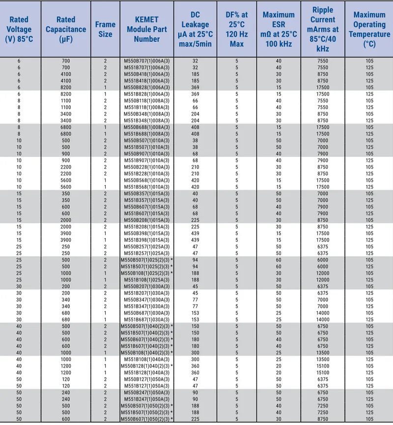
Table 1 – Ratings & Part Number Reference
(1) To complete KEMET part number, insert M for ±20% or K for ±10%. Designates capacitance tolerance.
(2) To complete KEMET part number, insert B = standard reliability, or T = high reliability. See Ordering Information table for details.
(3) To complete KEMET part number, insert T = 100% matte tin (Sn) plated, H = standard solder coated (SnPb 5% Pb minimum), S = 60% tin (Sn) 40% lead
(Pb) , G = 100% gold (Au) , A = 100% silver (Ag). Designates termination finish.
Rated
Voltage
(V) 85°C
Rated
Capacitance
(µF)
Frame
Size
KEMET
Module Part
Number
DC
Leakage
µA at 25°C
max/5min
DF% at
25°C
120 Hz
Max
Maximum
ESR
mΩ at 25°C
100 kHz
Ripple
Current
mArms at
85°C/40
kHz
Maximum
Operating
Temperature
(°C)
6 700 2 M550B707(1)006A(3) 32 5 40 7550 105
6 700 2 M551B707(1)006A(3) 32 5 40 7550 125
6 4100 2 M550B418(1)006A(3) 185 5 30 8750 105
6 4100 2 M551B418(1)006A(3) 185 5 30 8750 125
6 8200 1 M550B828(1)006A(3) 369 5 15 17500 105
6 8200 1 M551B828(1)006A(3) 369 5 15 17500 125
8 1100 2 M550B118(1)008A(3) 66 5 40 7550 105
8 1100 2 M551B118(1)008A(3) 66 5 40 7550 125
8 3400 2 M550B348(1)008A(3) 204 5 30 8750 105
8 3400 2 M551B348(1)008A(3) 204 5 30 8750 125
8 6800 1 M550B688(1)008A(3) 408 5 15 17500 105
8 6800 1 M551B688(1)008A(3) 408 5 15 17500 125
10 500 2 M550B507(1)010A(3) 38 5 50 7000 105
10 500 2 M551B507(1)010A(3) 38 5 50 7000 125
10 900 2 M550B907(1)010A(3) 68 5 40 7900 105
10 900 2 M551B907(1)010A(3) 68 5 40 7900 125
10 2200 2 M550B228(1)010A(3) 210 5 30 8750 105
10 2200 2 M551B228(1)010A(3) 210 5 30 8750 125
10 5600 1 M550B568(1)010A(3) 420 5 15 17500 105
10 5600 1 M551B568(1)010A(3) 420 5 15 17500 125
15 350 2 M550B357(1)015A(3) 40 5 50 7000 105
15 350 2 M551B357(1)015A(3) 40 5 50 7000 125
15 600 2 M550B607(1)015A(3) 68 5 40 7900 105
15 600 2 M551B607(1)015A(3) 68 5 40 7900 125
15 2000 2 M550B208(1)015A(3) 225 5 30 8750 105
15 2000 2 M551B208(1)015A(3) 225 5 30 8750 125
15 3900 1 M550B398(1)015A(3) 439 5 15 17500 105
15 3900 1 M551B398(1)015A(3) 439 5 15 17500 125
25 250 2 M550B257(1)025A(3) 47 5 50 6375 105
25 250 2 M551B257(1)025A(3) 47 5 50 6375 125
25 500 2 M550B507(1)025(2)(3) * 94 5 60 6000 105
25 500 2 M551B507(1)025(2)(3) * 94 5 60 6000 125
25 1000 1 M550B108(1)025(2)(3) * 188 5 30 12000 105
25 1000 1 M551B108(1)025A(3) 188 5 30 12000 125
30 200 2 M550B207(1)030A(3) 45 5 50 6375 105
30 200 2 M551B207(1)030A(3) 45 5 50 6375 125
30 340 2 M550B347(1)030A(3) 77 5 50 7000 105
30 340 2 M551B347(1)030A(3) 77 5 50 7000 125
30 680 1 M550B687(1)030A(3) 153 5 25 14000 105
30 680 1 M551B687(1)030A(3) 153 5 25 14000 125
40 500 2 M550B507(1)040(2)(3) * 150 5 50 6750 105
40 500 2 M551B507(1)040(2)(3) * 150 5 50 6750 125
40 600 2 M550B607(1)040(2)(3) * 180 5 40 6750 105
40 600 2 M551B607(1)040(2)(3) * 180 5 40 6750 125
40 1000 1 M550B108(1)040(2)(3) * 300 5 25 13500 105
40 1000 1 M551B108(1)040A(3) 300 5 25 13500 125
40 1200 1 M550B128(1)040(2)(3) * 360 5 20 15100 105
40 1200 1 M551B128(1)040A(3) 360 5 20 15100 125
50 120 2 M550B127(1)050A(3) 47 5 50 6375 105
50 120 2 M551B127(1)050A(3) 47 5 50 6375 125
50 240 2 M550B247(1)050A(3) 90 5 50 6750 105
50 240 2 M551B247(1)050A(3) 90 5 50 6750 125
50 500 2 M550B507(1)050(2)(3) * 188 5 40 7250 105
50 500 2 M551B507(1)050(2)(3) * 188 5 40 7250 125
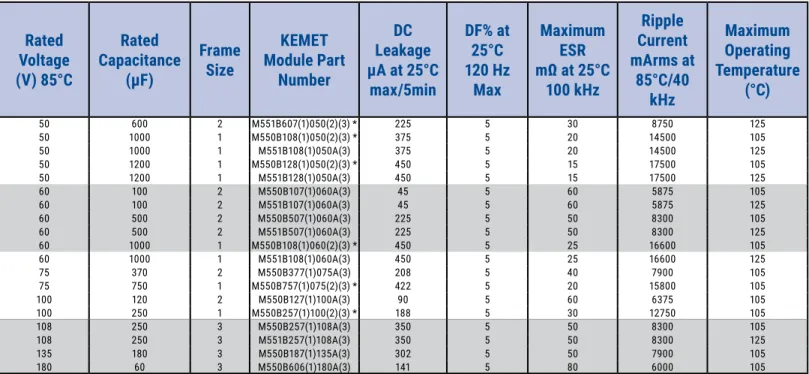
Table 1 – Ratings & Part Number Reference cont.
(1) To complete KEMET part number, insert M for ±20% or K for ±10%. Designates capacitance tolerance.
(2) To complete KEMET part number, insert B = standard reliability, or T = high reliability. See Ordering Information table for details.
(3) To complete KEMET part number, insert T = 100% matte tin (Sn) plated, H = standard solder coated (SnPb 5% Pb minimum), S = 60% tin (Sn) 40% lead
(Pb) , G = 100% gold (Au) , A = 100% silver (Ag). Designates termination finish.
Rated
Voltage
(V) 85°C
Rated
Capacitance
(µF)
Frame
Size
KEMET
Module Part
Number
DC
Leakage
µA at 25°C
max/5min
DF% at
25°C
120 Hz
Max
Maximum
ESR
mΩ at 25°C
100 kHz
Ripple
Current
mArms at
85°C/40
kHz
Maximum
Operating
Temperature
(°C)
50 600 2 M551B607(1)050(2)(3) * 225 5 30 8750 125
50 1000 1 M550B108(1)050(2)(3) * 375 5 20 14500 105
50 1000 1 M551B108(1)050A(3) 375 5 20 14500 125
50 1200 1 M550B128(1)050(2)(3) * 450 5 15 17500 105
50 1200 1 M551B128(1)050A(3) 450 5 15 17500 125
60 100 2 M550B107(1)060A(3) 45 5 60 5875 105
60 100 2 M551B107(1)060A(3) 45 5 60 5875 125
60 500 2 M550B507(1)060A(3) 225 5 50 8300 105
60 500 2 M551B507(1)060A(3) 225 5 50 8300 125
60 1000 1 M550B108(1)060(2)(3) * 450 5 25 16600 105
60 1000 1 M551B108(1)060A(3) 450 5 25 16600 125
75 370 2 M550B377(1)075A(3) 208 5 40 7900 105
75 750 1 M550B757(1)075(2)(3) * 422 5 20 15800 105
100 120 2 M550B127(1)100A(3) 90 5 60 6375 105
100 250 1 M550B257(1)100(2)(3) * 188 5 30 12750 105
108 250 3 M550B257(1)108A(3) 350 5 50 8300 105
108 250 3 M551B257(1)108A(3) 350 5 50 8300 125
135 180 3 M550B187(1)135A(3) 302 5 50 7900 105
Recommended Voltage Derating Guidelines
0% 10% 20% 30% 40% 50% 60% 70% 80% 90% 100%
-55 25 45 85 105 125
%
W
or
ki
ng
V
ol
ta
ge
Temperature (°C)
66% 78%
54%
Recommended Maximum Application Voltage % Change in Working DC Voltage
with temperature −55°C to 105°C 105°C to 125°C
% Change in Working DC
Voltage with Temperature 78% of VR 66% of VR
Recommended Maximum Application Voltage
(As % of Rated Voltage) 63% of VR 54% of VR
Ripple Current/Ripple Voltage
Permissible AC ripple voltage and current are related to equivalent series resistance (ESR) and the power dissipation
capabilities of the device. Permissible AC ripple voltage that may be applied is limited by two criteria:
1. The positive peak AC voltage plus the DC bias voltage, if any, must not exceed the DC voltage rating of the capacitor.
2. The negative peak AC voltage in combination with bias voltage, if any, must not exceed the allowable limits specified
for reverse voltage.
The maximum power dissipation by case size can be determined using the below left table. The maximum power dissipation
rating stated in the table must be reduced with increasing environmental operating temperatures. Refer to the below right
table for temperature compensation requirements.
Case Code
Maximum Power
Dissipation (P
max)
mWatts at 25°C
with +60°C Rise
KEMET MIL–PRF–39006/22/25/30/31 Case Size
B T2 715
Temperature Compensation Multipliers for
Maximum Power Dissipation (P
max)
T ≤ 45°C 45°C < T ≤ 85°C 85°C < T ≤ 125°C
1.00 0.70 0.10
T= Environmental Temperature
Using the P
maxof the device, the maximum allowable rms
ripple current or voltage may be determined.
I(max) = √Pmax/R E(max) = Z √Pmax/R
I = rms ripple current (amperes) E = rms ripple voltage (volts)
Pmax = maximum power dissipation (watts) R = ESR at specified frequency (ohms) Z = Impedance at specified frequency (ohms)
The maximum power dissipation rating must be reduced with increasing environmental operating temperatures. Refer to the Temperature Compensation Multiplier table for details.
Reverse Voltage
Solid tantalum polymer capacitors are polar devices and may
be permanently damaged or destroyed if connected with
the wrong polarity. A small reverse voltage is permissible
for time periods per the table at right. KEMET can offer
lower capacitance in this voltage with higher reverse voltage
capability. In addition, we continue to improve our capability
for this characteristic.
Mounting
The M550 and M551 Modular Series are suitable for stacking to the board. The use of a heat sink is recommended.
These products are not suitable for reflow soldering. For manual-soldering process with soldering iron, the maximum
recommended temperature is 350°C for no more than 3 seconds. Care should be taken to avoid contact of the soldering iron
to the epoxy housing. The iron should be used to heat the solder pad, applying solder between the pad and the terminal of
the module, until reflow occurs.
Temperature
Reverse Voltage
Permissible
25°C 1 V for 8 hours Maximum
Construction
Module 1
Detailed Cross Section
Tantalum Wire
Solder Ta2O5 Dielectric
(First Layer) Carbon (Third Layer)
Silver Paint (Fourth Layer)
Polymer (Second Layer)
Wire Lead (−)
Solder
Solder Wire Lead (+)
Anode Tube HermeticSeal System (Glass Seal and Ring)
Brass Can
Tantalum Molded Plastic Case
(Epoxy Potting Not Shown) Mounting Eyelet
(Brass)
Module Frame (Cu)
T550/T551 Capacitors (Qty = 10, Parallel)
Molded Plastic Case (Bottom Panel)
Terminals (See Ordering Information
for Finish Options)
Module 2
Molded Plastic Case
(Epoxy Potting Not Shown)
Mounting Eyelet
(Brass)
Module Frame
(Cu)
T550/T551 Capacitors
(Qty = 5, Parallel)
Molded Plastic Case
(Bottom Panel)
Terminals
(See Ordering Information
for Finish Options)
Construction cont.
Module 3
Molded Plastic Case
(Epoxy Potting Not Shown)
Mounting Eyelet
(Brass)
Module Frame
(Cu)
T550/T551 Capacitors
(Qty = 10, Parallel)
Molded Plastic Case
(Bottom Panel)
Terminals
(See Ordering Information
for Finish Options)
Capacitor Marking
KEMET ID
Polarity
Indicators
(
−
)(+)
Capacitance Code,
Tolerance Code
Series
Rated Voltage
(VDC)
4 Digit Date Code,
Batch Code
Storage
Polymer Hermetic Seal Modules should be stored in normal working environments. KEMET recommends that maximum
storage temperature not exceed 40°C and maximum storage humidity not exceed 90% RH. For optimal solderability, module
stock should be used promptly, preferably within three years of receipt.
Packaging
Modules shall be packaged in carton boxes. Packaging
methods and materials used shall prevent degradation of
physical and mechanical characteristics. MSL 1
Series
Carton Box Qty
KEMET Electronics Corporation Sales Offi ces
For a complete list of our global sales offi ces, please visit www.kemet.com/sales.
Disclaimer
All product specifi cations, statements, information and data (collectively, the “Information”) in this datasheet are subject to change. The customer is responsible for checking and verifying the extent to which the Information contained in this publication is applicable to an order at the time the order is placed. All Information given herein is believed to be accurate and reliable, but it is presented without guarantee, warranty, or responsibility of any kind, expressed or implied.
Statements of suitability for certain applications are based on KEMET Electronics Corporation’s (“KEMET”) knowledge of typical operating conditions for such applications, but are not intended to constitute – and KEMET specifi cally disclaims – any warranty concerning suitability for a specifi c customer application or use. The Information is intended for use only by customers who have the requisite experience and capability to determine the correct products for their application. Any technical advice inferred from this Information or otherwise provided by KEMET with reference to the use of KEMET’s products is given gratis, and KEMET assumes no obligation or liability for the advice given or results obtained.
Although KEMET designs and manufactures its products to the most stringent quality and safety standards, given the current state of the art, isolated component failures may still occur. Accordingly, customer applications which require a high degree of reliability or safety should employ suitable designs or other safeguards (such as installation of protective circuitry or redundancies) in order to ensure that the failure of an electrical component does not result in a risk of personal injury or property damage.
Although all product–related warnings, cautions and notes must be observed, the customer should not assume that all safety measures are indicted or that other measures may not be required.