A Step-by-Step Guide for Programming and Operating a
Complete Lutron RadioRA
®Wireless Central Home
Lighting Control System
Note: Please leave this manual with homeowner.
Setup Guide
FCC Information
NOTE: This equipment has been tested and found to comply with the limits for a Class B digital device, pursuant to part 15 of the FCC rules. These limits are designed to provide reasonable protection against harmful interference in a residential installation. This equipment generates, uses and can radiate radio frequency energy and, if not installed and used in accordance with the instructions, may cause harmful interference to radio or television reception, which can be determined by turning the equipment off and on, the user is encouraged to try to correct the interference by one or more of the following measures:
• Reorient or relocate the receiving antenna.
• Increase the separation between the equipment and receiver.
• Connect the equipment into an outlet on a circuit different from that to which the receiver is connected. • Consult the dealer or an experienced radio/TV technician for help.
Caution: Changes or modifications not expressly approved by Lutron Electronics Co. could void the user's authority to operate this equipment.
This symbol is intended to alert the user to the presence of important installation and operating instructions.
Consumer Information
Danger
This RadioRA® system must not be used to control equipment, other than lighting, which is not visible from every master or
local control location. It also must not be used to control equipment which could create hazardous situations such as entrapment if operated accidentally. Examples of equipment which must not be controlled by this RadioRA® system include
(but are not limited to) motorized gates, garage doors, industrial doors, and microwave ovens, heating pads, etc. It is the installer's responsibility to ensure that the equipment, other than lighting, being controlled is visible from every master or local control location and that only suitable equipment is connected to this RadioRA® system.
1. It is recommended that only one GRAFIK Eye® Control Unit be wired to each GRAFIK Eye® Interface. Multiple GRAFIK
Eye® Control Units may be wired (linked) to the same GRAFIK Eye® Interface, however, all GRAFIK Eye® Control Units on
that link will respond in unison to the commands from the GRAFIK Eye® Interface. ALL GRAFIK Eye® Control Units wired to
the same Interface will carry out ALL commands from the GRAFIK Eye® Interface (i.e. go to GRAFIK Eye® scene 3, Turn
OFF, etc...). Interface commands cannot be sent to one individual GRAFIK Eye® Control Unit on a link of multiple GRAFIK
Eye® Control Units.
• This application may be desired if multiple GRAFIK Eye® Control Units are in the same room and it is intended that
the same scene be selected on each GRAFIK Eye® Control Unit simultaneously.
• Lutron does not recommend using one GRAFIK Eye® Interface to linked GRAFIK Eye® Control Units located in more
than one room.
2. Scene 1 on a GRAFIK Eye® Control Unit is the default scene for ALL ON, SECURITY, and FLASH MODES. It is
recommended scene 1 on GRAFIK Eye® Control Units be set to full intensity with a fade time of zero seconds.
3. Setting the light levels for GRAFIK Eye® scenes should be done prior to any operations in this Setup Guide.
4. A GRAFIK Eye® scene may be added to any RadioRA® Master Control button which has been previously programmed
without altering that buttons existing programming.
5. See RadioRA® Application Note No.48 (P/N 366-730) for steps to activate GRAFIK Eye® scenes 5-16 from a RadioRA®
Master Control.
6. For information on integrating your RadioRA® system with an astronomic timeclock, photocell, telephone interface, car visor
control, shade motor control, etc... see the RadioRA® Application Notes on our web page at www.lutron.com/
applicationnotes/index.html.
7. RadioRA® lighting control systems use radio frequency technology for communication. Currently, RadioRA® lighting control
systems are available in two frequencies. To determine the frequency of a RadioRA® product, examine the model number
on the product’s unit label. The labels are located on the side of all “wallbox” products, and on the bottom of all “tabletop” products.
The second letter in all RadioRA®model numbers indicates the product’s frequency. For example: RA-600LM is an “A”
frequency product, whereas RB-600LM is a “B” frequency product.
Note: Do not mix RadioRA®“A” and “B” frequency products within the same system. Products with different frequencies
are not compatible.
If you have any questions concerning the installation or operation of this product, please call the Lutron Technical Support Center at 1-800-523-9466.
Table of Contents
Section 1 - Start-Up
Activating Your System
Activating Repeaters ... 1-1 Activating Controls ... 1-3
Programming Preparations
Filling out the System Programming Worksheet ... 1-6 Assigning a Column of Buttons as ROOMS or SCENES ... 1-7
ROOM Button Programming
Assigning Dimmers, Switches or GRAFIK Eye® Control Units to ROOM Buttons ... 1-9
Setting Light Levels/GRAFIK Eye® Scene Selection for ROOM Buttons ... 1-11
SCENE Button Programming
Assigning Dimmers, Switches or GRAFIK Eye® Control Units to SCENE Buttons ... 1-13
Setting Light Levels/GRAFIK Eye® Scene Selection for SCENE Buttons ... 1-15
Section 2 - Advanced Features
Advanced Programming
Programming the ALL ON Button ... 2-1 Programming the ALL OFF Button ... 2-3 Copying Button Programming ... 2-5 Erasing Button Programming ... 2-7
Section 3 - Expanding Your System
Adding Basic System Components
Adding an Auxiliary Repeater ... 3-1 Adding Controls ... 3-3
Adding a Switch Closure Interface
Activating a Switch Closure Interface ... 3-5 Assigning Dimmers, Switches or GRAFIK Eye® Control Units to Input Channels ... 3-7
Setting Light Levels/GRAFIK Eye® Scene Selection for Input Channels ... 3-10
Section 4 - Troubleshooting
Troubleshooting Guide
... 4-1Diagnostic Tools
BEEP Mode ... 4-3 FLASH Mode ... 4-4
Returning Components to Default Factory Settings
Master Controls ... 4-5 Switch Closure Interface ... 4-6 Dimmers ... 4-7 Switches ... 4-8 GRAFIK Eye® Interface ... 4-9
Repeaters ... 4-10
Activating Your System
Press and hold the ACTIVATE REPEATER button until the green ACTIVATE REPEATER LED begins to flash (approximately 3
seconds).
Important Notes:
1. If your system has only one Repeater, it must be assigned as a Main Repeater.
2. If your system has more than one Repeater, only
one can be assigned as a Main Repeater. 3. If an LED turns orange while activating your
system, a system error occurred, consult the Troubleshooting Guide.
Read each Step completely before
starting.
Step 1
Assign a Main Repeater
Any Repeater in the system can be the Main Repeater.
Note: The green AUXILIARY LED will initially be ON on all Repeaters.
MAIN
REPEATER
REPEATER
CONTROLS
ACTIVATE
BEEP
FLASH
VERIFY
AUXILIARY
Green MAIN LED is ON.
MAIN
REPEATER
REPEATER
CONTROLS
ACTIVATE
BEEP
FLASH
VERIFY
AUXILIARY
Press and hold the MAIN button until the green MAIN LED turns ON (approximately 3 seconds).
Activating Repeaters
Repeaters must be in their permanent location and all controls must be operating (dimmers and switches must be wired to a light) in order to be activated.
Section 1 - Start-Up
Green ACTIVATE REPEATER LED will stay ON when the Repeater has been activated.
• If you have only one Repeater proceed
to Step 4.
?
MAIN
REPEATER
REPEATER
CONTROLS
ACTIVATE
BEEP
FLASH
VERIFY
AUXILIARY MAIN
REPEATER
REPEATER
CONTROLS
ACTIVATE
BEEP
FLASH
VERIFY
AUXILIARY
If the ACTIVATE REPEATER LED turns orange, consult the Troubleshooting Guide, Section I or II.
Activating Your System
Press and hold the ACTIVATE REPEATER button until the green ACTIVATE REPEATER LED begins to flash (approximately 3
seconds).
Section 1 - Start-Up
• Repeat Step 3 to activate any remaining
Auxiliary Repeaters.
• Proceed to Step 4 when all Repeaters
have been activated.
MAIN
REPEATER
REPEATER
CONTROLS
ACTIVATE
BEEP
FLASH
VERIFY
AUXILIARY
Green ACTIVATE REPEATER LED will stay ON when Repeater has been activated.
MAIN
REPEATER
REPEATER
CONTROLS
ACTIVATE
BEEP
FLASH
VERIFY
AUXILIARY
?
If the ACTIVATE REPEATER LED turnsorange, consult the Troubleshooting Guide, Section I, II or III.Step 4
Complete Repeater activation
Step 3
Activate each Auxiliary
Repeater
Note: All remaining Repeaters must be Auxiliary Repeaters (up to 3).
Press and hold the ACTIVATE REPEATER button on any Repeater until the green ACTIVATE REPEATER LED turns OFF (approximately 3 seconds).
The green ACTIVATE REPEATER LED on
ALL Repeaters will turn OFF. The MAIN or AUXILIARY LED will remain ON.
• Repeater activation is now complete.
• Proceed to Activate Controls on page
1-3.
MAIN
REPEATER
REPEATER
CONTROLS
ACTIVATE
BEEP
FLASH
VERIFY
AUXILIARY
MAIN
REPEATER
REPEATER
CONTROLS
ACTIVATE
BEEP
FLASH
VERIFY
Activating Controls
Master Controls, Dimmers, Switches, and GRAFIK Eye® Control Units may be activated in any order.
Step 1
Begin Control activation
Press and hold the ACTIVATE CONTROLS button on any Repeater until the green ACTIVATE CONTROLS LED turns ON (approximately 3 seconds).
Step 2
Activate a Master Control
Go to any Master Control.
Middle row of LEDs will turn ON when Master Control has been activated.
?
Activating Your System
• Repeat Step 2 to activate any remaining
Master Controls.
Activate one Master Control at a time. Wait for the middle row of LEDs to turn ON before activating any remaining Master Controls.
Section 1 - Start-Up
Press any button.
• All LEDs will flutter, then
• Top and bottom row will flash alternately
• Proceed to Step 3 when all Master
Controls have been activated.
ALL ON ALL OFF
Tabletop Master OR Wall Master
If a Master Control fails to respond as
described above, consult the Troubleshooting Guide, Section VI or VII.
If the Activate Controls LED fails to turn ON, consult the Troubleshooting Guide, Section IV.
?
MAIN
REPEATER
REPEATER
CONTROLS
ACTIVATE
BEEP
FLASH
VERIFY
AUXILIARY
The green ACTIVATE CONTROLS LED on
ALL Repeaters will turn ON.
MAIN
REPEATER
REPEATER
CONTROLS
ACTIVATE
BEEP
FLASH
VERIFY
Step 3
Activate a Dimmer, Switch or
GRAFIK Eye
®Control Unit
Step 4
Complete Control activation
Activating Your System
Section 1 - Start-Up
Press and hold the ACTIVATE CONTROLS button on any Repeater until the green ACTIVATE CONTROLS LED turns OFF (approximately 3 seconds).
Go to any Dimmer, Switch or GRAFIK Eye®
Control Unit. Turn the Dimmer or Switch ON or OFF by pressing the tapswitch. On a GRAFIK Eye® Control Unit, change the selected scene
by pressing a scene button.
The light(s) that the Dimmer, Switch or GRAFIK Eye® Control Unit operate will turn
ON and OFF a few times when it has been activated.
Dimmer Switch
Activate one Dimmer, Switch or GRAFIK Eye®
Control Unit at a time. Wait for the control to flash its light(s) before activating any remaining controls.
• Repeat Step 3 to activate any remaining
Dimmers, Switches or GRAFIK Eye
®Control Units.
?
If a Dimmer, Switch or GRAFIK Eye® ControlUnit fails to respond as described above, consult the Troubleshooting Guide, Section V.
• Continued on next page.
MAIN
REPEATER
REPEATER
CONTROLS
ACTIVATE
BEEP
FLASH
VERIFY
AUXILIARY
The green ACTIVATE CONTROLS LED on
ALL Repeaters will turn OFF. The MAIN or AUXILIARY LED will remain on.
MAIN
REPEATER
REPEATER
CONTROLS
ACTIVATE
BEEP
FLASH
VERIFY
AUXILIARY
TRON
GRAFIK Eye®
Control Unit
Step 5
Verify that all Controls have
been activated
Press and hold the FLASH button on any Repeater until the green FLASH LED turns ON (approximately 3 seconds).
MAIN
REPEATER
REPEATER
CONTROLS
ACTIVATE
BEEP
FLASH
VERIFY
AUXILIARY
MAIN
REPEATER
REPEATER
CONTROLS
ACTIVATE
BEEP
FLASH
VERIFY
AUXILIARY
Green FLASH LED on all Repeaters will turn ON.
Master Controls, if activated, will flash all their LEDs. Make note of any Master Controls which are not activated.
Dimmers, Switches, and GRAFIK Eye®
Control Units, if activated, will flash the light(s) they control. Make note of any Dimmers, Switches or GRAFIK Eye® Control
Units which are not activated.
After verifying that all Master Controls,
Dimmers, Switches, and GRAFIK Eye® Control
Units are activated, press and hold the FLASH button on any Repeater until the green FLASH LED turns OFF (approximately 3 seconds).
Activating Your System
Section 1 - Start-Up
Green FLASH LED on all Repeaters will turn OFF.
If any Master Control, Dimmer, Switch or GRAFIK Eye® Control Unit has not been
activated, repeat Steps 1 through 5, starting on page 1-3.
• Master Controls, Dimmers, Switches,
and GRAFIK Eye
®Control Units are now
activated.
• Proceed to Programming Preparations
on page 1-6.
Tabletop Master
Wall Master
MAIN
REPEATER
REPEATER
CONTROLS
ACTIVATE
BEEP
FLASH
VERIFY
AUXILIARY
MAIN
REPEATER
REPEATER
CONTROLS
ACTIVATE
BEEP
FLASH
VERIFY
Programming Preparations
System Programming Worksheet
After the System has been activated, the Master Controls (M.C.) should be programmed so that a light or a group of lights can be controlled by one or more Master buttons. Prior to programming your system, complete the RadioRA® System Programming Worksheet (page 5-2).
Step 1
Record all Dimmer, Switch,
and GRAFIK Eye
®Control Unit
locations along the top of the
worksheet
(Accessory Dimmers and Accessory Switches do not need to be recorded.)
Step 4
Select Dimmers, Switches or
GRAFIK Eye
®Control Units
Select which Dimmers, Switches or GRAFIK Eye®
Control Units will be controlled by each Master Control button by going across the worksheet and placing a check in the corresponding box(es).
Step 5
Label Master Control buttons
Apply one of the supplied labels in the space under each button.
• Repeat Steps 1 through 5, for all Master
Controls in your system.
• Proceed to Assigning a Column of
Buttons as ROOMS or SCENES on page
1-7.
Step 2
Select a Master Control
Start with any Master Control and write down its type and location. Co ntro ls M.C.Type: M.C. Location:
1 2 3 4 5
1 2 3 4
Button # Label Master BR Dimmer Front Hall DimmerRear Hall Dimmer Den GRAFIK Eye Front Porch Switch
15 Button Tabletop Master BR
Section 1 - Start-Up
M.C.Type: M.C. Location:
1 2 3 4 5
1 2 3
Button # Label Master BR Dimmer Front Hall DimmerRear Hall Dimmer Den GRAFIK Eye Front P orch Switch
15 Button Tabletop Master BR M Bedrm Hall Den Co ntro ls Bath Hall M Bedrm ALL OFF ALL ON
Place ALL ON label here Place ALL OFF label here
Step 3
Record button names
Write name you have chosen for each button under the Label column of the worksheet. Refer to label sheets for names.
M.C.Type: M.C. Location:
1 2 3 4 5
1 2 3 4
Button # Label Master BR Dimmer Front Hall DimmerRear Hall Dimmer Den GRAFIK Eye Front P orch Switch
15 Button Tabletop Master BR M Bedrm Hall Den Outside Co ntro ls Controls
1 2 3 4 5
1 2 3 4
Programming Preparations
Assigning a Column of Buttons as ROOMS or SCENES
Each column of buttons on a Master Control can be programmed to be either ROOM or SCENE buttons.
If the first LED in a column is flashing, the buttons in that column are set as ROOM buttons.
If the second LED in a column is flashing, the buttons in that column are set as SCENE buttons.
ROOMS SCENES
Column of Buttons
Step 1
Begin ROOM/SCENE
assignment
Simultaneously press and hold the 3rd, 5th, and ALL OFF buttons in the right most column until an LED in each column of the Master Control which you are programming begins to flash (approximately 3 seconds).
Note: On a 5 button Raise/Lower Wall Master, press and hold the 3rd, 5th, and Lower
buttons.
Tabletop Master OR Wall Master
What is a ROOM button?
ROOM buttons can be used to turn a light or a group of lights ON or OFF. Pressing a ROOM button once will turn ON all Dimmers or Switches assigned to that button to their pre-selected light level. Pressing the same ROOM button again will turn OFF all Dimmers or Switches assigned to that button. A ROOM LED will be ON if any Dimmer or Switch assigned to that button is ON, regardless of its light level.
What is a SCENE button?
SCENE buttons can be used to direct any combination of Dimmers and/or Switches to a pre-selected state or light level. Pressing a SCENE button once will turn ON any Dimmers or Switches assigned to turn ON, and turn OFF any Dimmers or Switches assigned to turn OFF. Pressing the same SCENE button again will turn OFF all Dimmers or Switches assigned to that button. A SCENE LED on a Master Control will be ON if, and only if, that SCENE button was pressed on that Master Control. An example of a SCENE application could be a button called "BEDTIME", which when pressed all interior lights would turn OFF and selected outside lights would turn ON.
Section 1 - Start-Up
All button columns are factory set as ROOM buttons.
Changing a column assignment from ROOM to SCENE (or vice versa) will delete all previous programming in that column of buttons.
Programming Preparations
Step 3
Complete ROOM/SCENE
assignment
Simultaneously press and hold the 3rd, 5th, and ALL OFF buttons in the right most column until the LEDs stop flashing (approximately 3 seconds).
Note: On a 5 button Raise/Lower Wall Master, press and hold the 3rd, 5th, and Lower
buttons.
Step 4
Label columns
Apply the supplied ROOMS or SCENES labels to the space provided over each button
column.
SCENES ROOMS ROOMS
Step 2
Changing ROOM/SCENE
assignments
Press the 1st button in a column to make that column a ROOM column, or press the 2nd button to make it a SCENE column.
ALL OFF ALL ON
ROOMS SCENES
Section 1 - Start-Up
Shown: Setting left most column as SCENES.
ROOM Button Programming
Assigning Dimmers, Switches or GRAFIK Eye
®Control
Units to ROOM Buttons
NOTE: A column of buttons can also be assigned as SCENES (see page 1-7).
Step 3
Assign a Dimmer, Switch or
GRAFIK Eye
®Control Unit
Control to the button
Notes:
• Multiple Dimmers, Switches or GRAFIK Eye® Control
Units can be assigned to a single ROOM button. • Controls must be assigned to a Master Control
button while its LED is flashing.
Section 1 - Start-Up
Assign Dimmers or Switches to the Master Control button by turning the Controls ON. Assign a GRAFIK Eye® Control Unit to the
Master Control button by changing the selected GRAFIK Eye® scene.
If you assign the wrong Dimmer, Switch or GRAFIK Eye® Control Unit
to a Master Control button, turn the Dimmer, Switch or GRAFIK Eye®
Control Unit OFF to unassign it.
Switch Dimmer
OR
TRON
Note: GRAFIK Eye® Control Units will automatically
turn on to scene 1 once assigned.
Step 1
Begin assigning Dimmers,
Switches, or GRAFIK Eye
®Control Units to ROOM
buttons
Simultaneously press and hold the 2nd and 4th buttons in the right most column until the upper right LED begins to flash (approximately 3 seconds).
Tabletop Master OR Wall Master
Upper right LED flashes.
ALL ON ALL OFF
Step 2
Select a ROOM Button
Press and release the ROOM button that you want to program. It's LED will begin to flash.
GRAFIK Eye®
ROOM Button Programming
Step 5
Complete assigning Dimmers,
Switches, and GRAFIK Eye
®Control Units
Step 4
Select next ROOM button
To assign Dimmers, Switches or GRAFIK Eye® Control Units to another Master Control
ROOM button, press and release that button. Its LED will begin to flash.
• Proceed to Step 5 when all ROOM
buttons on this Master Control have
been programmed.
Section 1 - Start-Up
• Repeat Steps 1 through 5 to assign
Dimmers, Switches or GRAFIK Eye
®Control Units to ROOM buttons on any
additional Master Controls.
• Pressing a newly programmed ROOM
button at this point will turn assigned:
Dimmers on to 100% light, Switches ON,
and GRAFIK Eye
®Control Units ON to
scene 1.
• Proceed to Setting Light Levels/GRAFIK
Eye
®Scene Selection for ROOM Buttons
on page 1-11.
Simultaneously press and hold the 2nd and 4th buttons in the right most column until all LEDs begin to flutter (approximately 3 seconds).
Perform Step 3 for this newly selected ROOM button.
ROOM Button Programming
Setting Light Levels/GRAFIK Eye
®Scene Selection for
ROOM Buttons
Note: Dimmers can be set to a variable light level. Switches must remain ON. GRAFIK Eye® Control Units can be
set to any scene.
Step 1
Begin setting light levels/
selecting GRAFIK Eye
®scenes
Simultaneously press and hold the 1st and 5th buttons in the right most column until the upper right LED begins to blink (approximately 3 seconds).
Step 3
Set light levels for Dimmers
Use the dimming rocker to adjust the light level of any Dimmer(s) assigned to that button. This is the light level that the Dimmers will turn ON to when the ROOM button is pressed ON.
Section 1 - Start-Up
Tabletop Master OR Wall Master
Upper right LED blinks.
Step 2
Select a ROOM Button
Press and release the ROOM button that you want to program. It's LEDs will begin to blink.
The GRAFIK Eye® Control Unit will turn ON to
the scene selected in this step when the ROOM button is pressed ON. The last scene selected on the GRAFIK Eye® Control Unit will be the
scene programmed to the ROOM button.
Step 4
Select a GRAFIK Eye
®scene
At the GRAFIK Eye® Control Unit, select one
of the pre-programmed scenes (1 through 4) by turning that scene ON.
LUTRON
While setting light levels
• Dimmers assigned to a Master Control ROOM button cannot be turned OFF. • Dimmers not assigned to a Master Control
ROOM button cannot be turned ON.
Dimmers, Switches, and GRAFIK Eye® Control Units
that have been assigned to that button will turn ON. Devices not assigned to that button will turn OFF.
ALL ON ALL OFF
ROOM Button Programming
Step 6
Complete setting light levels/
selecting GRAFIK Eye
®scenes
Step 5
Select the next ROOM button
To set the Dimmer light level/select a GRAFIK Eye® scene for another ROOM button, press
that button. Its LED will begin to blink.
• Proceed to Step 6 when all ROOM
buttons on this Master Control have
been programmed.
Section 1 - Start-Up
Simultaneously press and hold the 1st and 5th buttons in the right most column until all LEDs begin to flutter (approximately 3 seconds).
• Repeat Steps 1 through 6 to set the light
levels/select GRAFIK Eye
®scenes on
any remaining Master Controls.
• To copy the button programming from
one Master Control to another Master
Control, see Copy Button Programming
on page 2-5 of the Advance Features
Section of this guide.
Congratulations.
Your system is now
programmed. Relax and enjoy your system.
Perform Steps 3 and 4 (whichever apply) forSCENE Button Programming
Assigning Dimmers, Switches or GRAFIK Eye
®Control
Units to SCENE Buttons
Note: A column of buttons can also be assigned as ROOMS (see page 1-7).
Step 1
Begin assigning Dimmers,
Switches or GRAFIK Eye
®Control Units to SCENE
buttons
Step 3
Assign Dimmers, Switches or
GRAFIK Eye
®Control Units to
the button
Note: Multiple Dimmers, Switches or GRAFIK Eye®
Control Units can be assigned to a single SCENE button.
Step 2
Select a SCENE button
Press and release the SCENE button that you want to program. Its LED will begin to flash.
Simultaneously press and hold the 2nd and 4th buttons in the right most column until the upper right LED begins to flash (approximately 3 seconds).
If you assign the wrong Dimmer, Switch or GRAFIK Eye® Control Unit to
a Master Control button, turn the Dimmer, Switch or GRAFIK Eye®
Control Unit OFF to unassign it.
In this Step you must not only assign light controls which you want to turn ON when the button is pressed, you must also assign light controls which you want to turn OFF when the button is pressed.
Assign a GRAFIK Eye® Control Unit to the
selected SCENE button by changing the scene of the GRAFIK Eye® Control Unit.
LUTRON
Note: GRAFIK Eye® Control Units will automatically
turn ON to scene 1 once assigned. Upper right LED flashes.
Tabletop Master OR Wall Master
Assign a Dimmer or Switch to the selected SCENE button by turning the Dimmer or Switch ON.
Switch
OR
Dimmer
Section 1 - Start-Up
ALL ONSCENE Button Programming
Step 4
Select next SCENE button
Step 5
Complete assigning Dimmers,
Switches, and GRAFIK Eye
®Control Units
To assign Dimmers, Switches or GRAFIKEye® Control Units to another Master Control
SCENE button, press and release that button. Its LED will begin to flash.
ALL OFF
ALL ONALL ON ALL OFF
Simultaneously press and hold the 2nd and 4th buttons in the right most column until all the LEDs begin to flutter (approximately 3 seconds).
Perform Step 3 for this newly selected SCENE button.
• Proceed to Step 5 when all SCENE
buttons on this Master Control have
been programmed.
Section 1 - Start-Up
• Repeat Steps 1 through 5 to assign
Dimmers, Switches or GRAFIK Eye
®Control Units to SCENE buttons on any
additional Master Controls.
• Pressing a newly programmed SCENE
button at this point will turn assigned:
Dimmers on to 50% light, Switches ON,
and GRAFIK Eye
®Control Units ON to
Setting Light Levels/GRAFIK Eye
®Scene Selection for
SCENE Buttons
Note: Dimmers can be set to a variable light level or turned OFF. Switches can be turned ON or OFF. GRAFIK Eye® Control Units can be set to any scene or turned OFF.
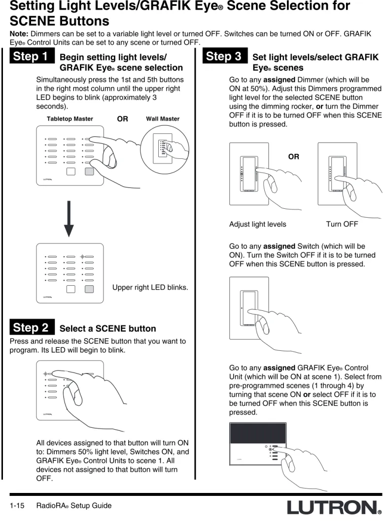
Step 1
Begin setting light levels/
GRAFIK Eye
®scene selection
Step 3
Set light levels/select GRAFIK
Eye
®scenes
SCENE Button Programming
Simultaneously press the 1st and 5th buttons in the right most column until the upper right LED begins to blink (approximately 3 seconds).
Step 2
Select a SCENE button
Press and release the SCENE button that you want to program. Its LED will begin to blink.
Go to any assigned Dimmer (which will be ON at 50%). Adjust this Dimmers programmed light level for the selected SCENE button using the dimming rocker, or turn the Dimmer OFF if it is to be turned OFF when this SCENE button is pressed.
Adjust light levels Turn OFF
OR
LUTRON
Go to any assigned GRAFIK Eye® Control
Unit (which will be ON at scene 1). Select from pre-programmed scenes (1 through 4) by turning that scene ON or select OFF if it is to be turned OFF when this SCENE button is pressed.
Go to any assigned Switch (which will be ON). Turn the Switch OFF if it is to be turned OFF when this SCENE button is pressed.
All devices assigned to that button will turn ON to: Dimmers 50% light level, Switches ON, and GRAFIK Eye® Control Units to scene 1. All
devices not assigned to that button will turn OFF.
Upper right LED blinks. ALL ON ALL OFF
Tabletop Master OR Wall Master
Step 5
Complete setting light levels/
selecting GRAFIK Eye
®scenes
Step 4
Select next SCENE button
To set the light level for another Master Control SCENE button, press and release that button. Its LEDs will begin to blink.
SCENE Button Programming
ALL OFF
ALL ONALL ON ALL OFF
If at any point in this procedure you are unsure which Dimmers, Switches or GRAFIK Eye®
Control Units are assigned to a Master Control SCENE button
• Press the button next to the blinking LED. • The LED will begin to flash (slower) and all
Dimmers, Switches, and GRAFIK Eye®
Control Units assigned to that Master Control SCENE button will turn ON to full intensity.
Note: Dimmer, Switch or GRAFIK Eye®
Control Unit assignments cannot be changed at this time. See page 1-13 to change control assignment.
• Press the same Master Control SCENE button again to continue setting light levels. The LED will begin to blink again (faster). Perform Step 3 for this newly selected SCENE
button.
• Repeat Steps 1 through 5 to set the light
levels/select GRAFIK Eye
®scenes on
any remaining Master Controls.
• To copy the button programming from
one Master Control to another Master
Control, see Copy Button Programming
on page 2-5.
• Proceed to Step 5 when all SCENE
buttons on this Master Control have
been programmed.
Simultaneously press the 1st and 5th buttons in the right most column until all LEDs begin to flutter (approximately 3 seconds).
Advanced Programming
Section 2 -
Advanced Features
Step 1
Begin the ALL ON button
programming
Programming the ALL ON Button
The ALL ON button on a RadioRA® Master Control will, by default, turn ON all Dimmers and Switches to full
intensity, and GRAFIK Eye® Control Units to Scene 1 when pressed. The ALL ON button can be programmed to
turn ON selected Dimmers (to full intensity), Switches, or GRAFIK Eye Control Units (to Scene 1).
Step 2
Press the ALL ON button
On the Master Control you want to program, simultaneously press and hold the 2nd and 4th buttons in the right most column until the upper right LED begins to flash (approximately 3 seconds).
Press the ALL ON button on the Master Control you are programming.
Upper right LED flashes.
Tabletop Master OR Wall Master
The LEDs in all columns will simultaneously cycle from bottom to top.
LEDs cycle UP
All Dimming/Switching Controls and GRAFIK Eye® Control Units will turn ON.
ALL ON ALL OFF These programming steps only apply to Master Controls equipped with an ALL ON button.
Advanced Programming
Section 2 -
Advanced Features
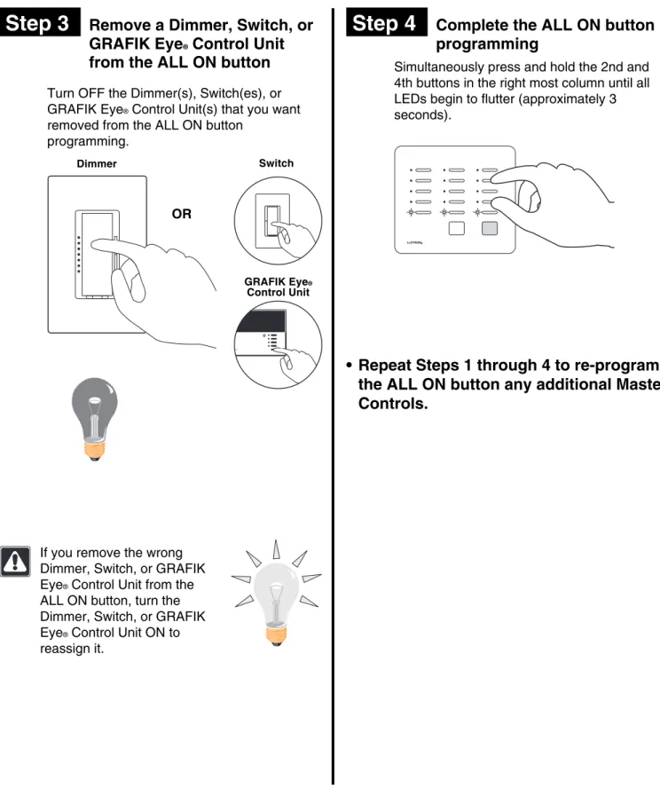
Step 3
Remove a Dimmer, Switch, or
GRAFIK Eye
®Control Unit
from the ALL ON button
Step 4
Complete the ALL ON button
programming
Simultaneously press and hold the 2nd and 4th buttons in the right most column until all LEDs begin to flutter (approximately 3 seconds).
Turn OFF the Dimmer(s), Switch(es), or GRAFIK Eye® Control Unit(s) that you want
removed from the ALL ON button programming.
Dimmer
If you remove the wrong Dimmer, Switch, or GRAFIK Eye® Control Unit from the
ALL ON button, turn the Dimmer, Switch, or GRAFIK Eye® Control Unit ON to
reassign it.
Switch
OR
TRON
• Repeat Steps 1 through 4 to re-program
the ALL ON button any additional Master
Controls.
GRAFIK Eye®
Advanced Programming
Section 2 -
Advanced Features
Step 1
Begin the ALL OFF button
programming
Programming the ALL OFF Button
The ALL OFF button on a RadioRA® Master Control will, by default, turn OFF all Dimmers, Switches, and GRAFIK
Eye® Control Units when pressed. The ALL OFF button can be programmed to turn selected Dimmers, Switches,
or GRAFIK Eye® Control Units OFF.
Step 2
Press the ALL OFF button
On the Master Control you want to program, simultaneously press and hold the 2nd and 4th buttons in the right most column until the upper right LED begins to flash (approximately 3 seconds).
Press the ALL OFF button on the Master Control you are programming.
Upper right LED flashes.
Tabletop Master OR Wall Master
The LEDs in all columns will simultaneously cycle from top to bottom.
LEDs cycle DOWN
All Dimming/Switching Controls and GRAFIK Eye® Control Units will turn ON.
ALL ON ALL OFF These programming steps only apply to Master Controls equipped with an ALL OFF button.
Advanced Programming
Section 2 -
Advanced Features
Step 3
Remove a Dimmer, Switch, or
GRAFIK Eye
®Control Unit
from the ALL OFF button
Step 4
Complete the ALL OFF button
programming
Simultaneously press and hold the 2nd and 4th buttons in the right most column until all the LEDs begin to flutter (approximately 3 seconds).
Turn OFF the Dimmer(s), Switch(es), or GRAFIK Eye® Control Unit(s) that you want
removed from the ALL OFF button.
Dimmer
If you remove the wrong Dimmer, Switch, or GRAFIK Eye® Control Unit from the
ALL OFF button, turn the Dimmer, Switch, or GRAFIK Eye® Control Unit ON to
reassign it.
Switch
OR
TRON
• Repeat Steps 1 through 4 to re-program
the ALL OFF button any additional
Master Controls.
GRAFIK Eye®
Step 1
Begin Copying Button
Programming
Copying Button Programming
If you have more than one Master Control in your system, you can copy the button programming from a
previously programmed Master Control button to an un-programmed Master Control button so that both buttons function identically.
Step 2
Select the button you want to
program
Advanced Programming
Section 2 -
Advanced Features
On the Master Control you want to program, simultaneously press and hold the 1st and 5th buttons in the right most column until the upper right LED begins to blink (approximately 3 seconds).
Press and release the button you want to program. Its LED will begin to blink.
Un-programmed Master Control
ALL ON ALL OFF
Tabletop Master OR Wall Master
Un-programmed Master Control
Upper right LED blinks.
Note: LEDs on all other Master Controls will flash.
Un-programmed Master Control
Un-programmed Master Control
The programming from a ROOM button cannot be copied to a SCENE button, or vice versa.
Step 3
Select the button you want to
copy
Step 4
Complete Copy Button
Programming
Advanced Programming
Section 2 -
Advanced Features
On a previously programmed Master Control, press the programmed button that you want to copy until its LED turns OFF (approximately 3 seconds).
Simultaneously press and hold the 1st and 5th buttons in the right most column until all LEDs begin to flutter (approximately 3 seconds).
• Repeat Steps 2 and 3 for all Master
Control buttons that you want to copy
programming to.
When the LED turns OFF for a few seconds and then resumes flashing programming has been copied to
Previously Programmed Master Control
Previously Programmed Master Control
• Repeat Steps 1 through 4 to copy button
programming on any remaining
unprogrammed Master Controls.
Newly Programmed Master Control
Newly Programmed Master Control
Erasing Button Programming
Erasing Button Programming will remove all Dimming or Switching Controls assigned to a Master Control button and erase that button's programming.
Advanced Programming
Step 1
Begin Erasing Button
Programming
Simultaneously press the 2nd and 4th buttons in the right most column until the upper right LED begins to flash (approximately 3 seconds).
Step 2
Select button to erase
Press and hold the button you wish to erase until its LED begins to flutter (approximately 3 seconds).
Section 2 -
Advanced Features
Upper right LED flashes.
ALL OFF
ALL ONALL ON ALL OFF
LED will flutter for only 3 seconds.
Note: The LED will first flash (slower) and then begin to flutter (faster).
Advanced Programming
Step 3
Erase button
While the LED is fluttering, press the ALL OFF or Lower button in the right most column.
Step 4
Complete Erasing Button
Programming
Simultaneously press the 2nd and 4th buttons in the right most column until all LEDs begin to flutter (approximately 3 seconds).
Section 2 -
Advanced Features
The LED will stop fluttering and begin to flash. All Dimmers and/or Switches will turn OFF, and programming is now erased from that Master Control button.
• Repeat Steps 2 and 3 for all Master
Control buttons with programming that
you want to erase.
Wall Master Tabletop Master OR
Adding an Auxiliary Repeater
Auxiliary Repeaters (up to a maximum of 3) can be added to a system to increase range and improve reliability. Ensure all system devices are powered up and operating prior to adding any Auxiliary Repeaters.
Adding Basic System Components
MAIN
REPEATER
REPEATER
CONTROLS
ACTIVATE
BEEP
FLASH
VERIFY
AUXILIARY
MAIN
REPEATER
REPEATER
CONTROLS
ACTIVATE
BEEP
FLASH
VERIFY
AUXILIARY
?
Step 1
Begin Auxiliary Repeater
Activation
If the ACTIVATE REPEATER LED turns orange, consult the Troubleshooting Guide, Sections I.
Green Activate Repeater LED will turn ON on all existing system Repeaters.
Step 2
Activate Auxiliary Repeater
If the ACTIVATE REPEATER LED turns orange, consult the Troubleshooting Guide, Section I, II or III.
?
MAIN
REPEATER
REPEATER
CONTROLS
ACTIVATE
BEEP
FLASH
VERIFY
AUXILIARY
Green LED will stay ON when Repeater has been activated.
MAIN
REPEATER
REPEATER
CONTROLS
ACTIVATE
BEEP
FLASH
VERIFY
AUXILIARY
Press and hold the ACTIVATE REPEATER button on the new Auxiliary Repeater until the green ACTIVATE REPEATER LED begins to flash (approximately 3 seconds).
Section 3 - Expanding
Y
our System
Press and hold the ACTIVATE REPEATER button on any previously activated Repeater until the green ACTIVATE REPEATER LED turns ON (approximately 3 seconds).
Adding Basic System Components
Step 3
Complete Repeater activation
The green ACTIVATE REPEATER LED on
ALL Repeaters will turn OFF. The MAIN or AUXILIARY green LED will remain ON.
• Repeaters are now activated.
Press and hold the ACTIVATE REPEATER button on any Repeater until the green ACTIVATE REPEATER LED turns OFF (approximately 3 seconds).
Section 3 - Expanding
Y
our System
MAIN
REPEATER
REPEATER
CONTROLS
ACTIVATE
BEEP
FLASH
VERIFY
AUXILIARY
MAIN
REPEATER
REPEATER
CONTROLS
ACTIVATE
BEEP
FLASH
VERIFY
Adding Controls
Master Controls may be added to your system up to a maximum of 12. Dimmers, Switches, and GRAFIK Eye®
Control Units may be added up to a maximum of 32.
Adding Basic System Components
Step 1
Begin control activation
Press and hold the ACTIVATE CONTROLS button on any Repeater until the green ACTIVATE CONTROLS LED turns ON (approximately 3 seconds).
Step 2
Activate Controls
To add a Master Control
Go to the new Master Control.Note: All LEDs will be OFF prior to activation.
Section 3 - Expanding
Y
our System
Middle row of LEDs will turn ON when the Master Control has been activated.
ALL ON ALL OFF
Wall Master
OR
Tabletop Master
Press any button.
• All LEDs will flutter, then
• Top and bottom row will flash alternately
MAIN
REPEATER
REPEATER
CONTROLS
ACTIVATE
BEEP
FLASH
VERIFY
AUXILIARY
The green ACTIVATE CONTROLS LED on
ALL Repeaters will turn ON.
MAIN
REPEATER
REPEATER
CONTROLS
ACTIVATE
BEEP
FLASH
VERIFY
AUXILIARY
?
If the Activate Controls LED fails to turn ON,consult the Troubleshooting Guide, Section IV.Activate one Master Control at a time. Wait for the middle row of LEDs to turn ON before activating any remaining Master Controls.
Repeat the above Step to activate any
remaining Master Controls
If a Master Control fails to respond as
described above, consult the Troubleshooting Guide, Section VI or VII.
Adding Basic System Components
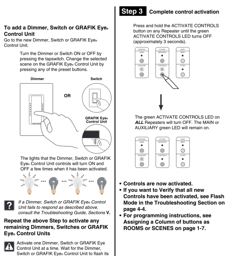
Step 3
Complete control activation
Press and hold the ACTIVATE CONTROLS button on any Repeater until the green ACTIVATE CONTROLS LED turns OFF (approximately 3 seconds).
To add a Dimmer, Switch or GRAFIK Eye
®Control Unit
Go to the new Dimmer, Switch or GRAFIK Eye®
Control Unit.
Section 3 - Expanding
Y
our System
Turn the Dimmer or Switch ON or OFF by pressing the tapswitch. Change the selected scene on the GRAFIK Eye® Control Unit by
pressing any of the preset buttons.
Activate one Dimmer, Switch or GRAFIK Eye Control Unit at a time. Wait for the Dimmer,
The lights that the Dimmer, Switch or GRAFIK Eye® Control Unit controls will turn ON and
OFF a few times when it has been activated.
If a Dimmer, Switch or GRAFIK Eye® Control
Unit fails to respond as described above, consult the Troubleshooting Guide, Sections V.
?
Repeat the above Step to activate any
remaining Dimmers, Switches or GRAFIK
Eye
®Control Units
MAIN
REPEATER
REPEATER
CONTROLS
ACTIVATE
BEEP
FLASH
VERIFY
AUXILIARY
The green ACTIVATE CONTROLS LED on
ALL Repeaters will turn OFF. The MAIN or AUXILIARY green LED will remain on.
MAIN
REPEATER
REPEATER
CONTROLS
ACTIVATE
BEEP
FLASH
VERIFY
AUXILIARY
• Controls are now activated.
• If you want to Verify that all new
Controls have been activated, see Flash
Mode in the Troubleshooting Section on
page 4-4.
• For programming instructions, see
Assigning a Column of buttons as
ROOMS or SCENES on page 1-7.
Dimmer Switch
TRON
OR
GRAFIK Eye®
Adding a Switch Closure Interface
Section 3 - Expanding
Y
our System
Activating a Switch Closure Interface
The Switch Closure Interface is a special type of Master Control. Therefore, the System can have a maximum of 12 Master Controls plus a Switch Closure Interface. For every 1 Master Control NOT used, 1 Switch Closure Interface may be used in its place.
Step 2
Activate Switch Closure
Interface
?
If a Switch Closure Interface fails to respond asdescribed above, consult the Troubleshooting Guide, Section XI.• All input LEDs will flutter, then • The Flash LED and Input 1 LED will
alternately flash.
Step 1
Begin Switch Closure
Interface activation
Press and hold the ACTIVATE CONTROLS button on any Repeater until the green ACTIVATE CONTROLS LED turns ON (approximately 3 seconds).
MAIN
REPEATER
REPEATER
CONTROLS
ACTIVATE
BEEP
FLASH
VERIFY
AUXILIARY
The green ACTIVATE CONTROLS LED on
ALL Repeaters will turn ON.
MAIN
REPEATER
REPEATER
CONTROLS
ACTIVATE
BEEP
FLASH
VERIFY
AUXILIARY
Press any button.
Guide for operating instructions.
For additional assistance call the Lutron Technical Assistance
Hotline: 1-800-523-9466
FCC ID JPZ0005
This device complies with part 15 of the FCC Rules. Operation is subject to the following two conditions: (1) This device may not cause harmful interference and (2) This device must accept any interference received including interference that may cause undesired operation.
Patents Pending
18V AC IN
Full Flash Input 1 Input 2 Input 3 Input 4 Input 5 Common
Guide for o erating instructions.
For additional assistance call the Lutron Technical Assistance
Hotline: 1-800-523-9466
FCC ID JPZ0005
This device complies with part 15 of the FCC Rules. Operation is subject to the following two conditions: (1) This device may not cause harmful interference and (2) This device must accept any interference received including interference that may cause undesired operation.
Patents Pending
18V AC IN
Full Flash Input 1 Input 2 Input 3 Input 4 Input 5 Common
Input 4 LED will remain ON when the Switch Closure Interface has been activated. The Switch Closure Interface has a 15 second
delay after applying power. During this time the Power LED will blink. When the Power LED stays ON, the unit is ready for operation.
Adding a Switch Closure Interface
Section 3 - Expanding
Y
our System
Step 3
Complete Switch Closure
Interface activation
Press and hold the ACTIVATE CONTROLS button on any Repeater until the green ACTIVATE CONTROLS LED turns OFF (approximately 3 seconds).
• The Switch Closure Input Interface is
now activated.
• If you want to Verify that your Switch
Closure Interface has been activated,
see Flash Mode in the Troubleshooting
Section on page 4-4.
• Proceed to Assigning a Dimmers,
Switches or GRAFIK Eye
®Control Units
to Input Channels on page 3-7.
MAIN
REPEATER
REPEATER
CONTROLS
ACTIVATE
BEEP
FLASH
VERIFY
AUXILIARY
The green ACTIVATE CONTROLS LED on
ALL Repeaters will turn OFF. The MAIN or AUXILIARY LED will remain on.
MAIN
REPEATER
REPEATER
CONTROLS
ACTIVATE
BEEP
FLASH
VERIFY
Section 3 - Expanding
Y
our System
Adding a Switch Closure Interface
Step 1
Begin assigning Dimmers,
Switches or GRAFIK Eye
®Control Units to Input
Channels
Assigning Dimmers, Switches or GRAFIK Eye
®Control
Units to Input Channels
Programming the Switch Closure Interface to control a light or a group of lights by a specified Input Channel.
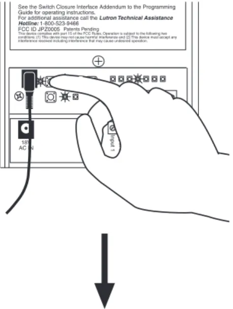
Step 2
Select an Input Channel to
program
Press and release the Input Select button until the LED for the desired input channel turns ON.
Selected Switch Closure Input Channel will have its LED ON.
See the Switch Closure Interface Addendum to the Programming Guide for operating instructions.
For additional assistance call the Lutron Technical Assistance
Hotline: 1-800-523-9466
FCC ID JPZ0005
This device complies with part 15 of the FCC Rules. Operation is subject to the following two conditions: (1) This device may not cause harmful interference and (2) This device must accept any interference received including interference that may cause undesired operation.
Patents Pending
18V AC IN
Full Flash Input 1 Input 2 Input 3 Input 4 Input 5 Common
18V AC IN
Full Flash Input 1 Input 2 Input 3 Input 4 Input 5 Common See the Switch Closure Interface Addendum to the Programming Guide for operating instructions.
For additional assistance call the Lutron Technical Assistance
Hotline: 1-800-523-9466
FCC ID JPZ0005
This device complies with part 15 of the FCC Rules. Operation is subject to the following two conditions: (1) This device may not cause harmful interference and (2) This device must accept any interference received including interference that may cause undesired operation.
Patents Pending
Simultaneously press and hold the Program and Input Select buttons until the Program LED begins to flash (approximately 3 seconds).
18V AC IN
Full Flash Input 1 Input 2 Input 3 Input 4 Input 5 Common
In ut 5 See the Switch Closure Interface Addendum to the Programming Guide for operating instructions.
For additional assistance call the Lutron Technical Assistance
Hotline: 1-800-523-9466
FCC ID JPZ0005
This device complies with part 15 of the FCC Rules. Operation is subject to the following two conditions: (1) This device may not cause harmful interference and (2) This device must accept any interference received including interference that may cause undesired operation.
Patents Pending
Program LED flashes. Input 1 LED and a Closure Type LED will turn ON.
18V AC IN
Full Flash Input 1 Input 2 Input 3 Input 4 Input 5 Common See the Switch Closure Interface Addendum to the Programming Guide for operating instructions.
For additional assistance call the Lutron Technical Assistance
Hotline: 1-800-523-9466
FCC ID JPZ0005
This device complies with part 15 of the FCC Rules. Operation is subject to the following two conditions: (1) This device may not cause harmful interference and (2) This device must accept any interference received including interference that may cause undesired operation.
Section 3 - Expanding
Y
our System
Adding a Switch Closure Interface
Step 4
Select Input Channel switch
closure type
Step 3
Assign Dimmers, Switches or
GRAFIK Eye
®Control Units to
Input Channel
To assign an input channel switch closuretype, press the Closure Type button to toggle between a Momentary and a Maintained input.
Note: Momentary inputs must be closed for a minimum of 100 msec.
18V AC IN
Full Flash Input 1 Input 2 Input 3 Input 4 Input 5 Common FCC ID JPZ0005
This device complies with part 15 of the FCC Rules. Operation is subject to the following two conditions: (1) This device may not cause harmful interference and (2) This device must accept any interference received including interference that may cause undesired operation.
Patents Pending
Maintained Momentary
Activate
Switch ReleaseSwitch Switch
Open
Momentary Input Example
A Momentary switch closure will turn a SCENE ON. The input SCENE remains ON after the switch closure has been released, until the
Activate
Switch ReleaseSwitch Switch
Open
A Maintained switch closure will turn an input SCENE ON. Input SCENE remains ON until the switch closure is released. When released, the input SCENE returns to OFF..
Maintained Input Example
• Inputs 1 through 5 can be independently selected as Maintained or Momentary. • Full and Flash are Maintained closures and
cannot be changed.
In this Step you must not only assign light controls which you want to turn ON when the Input Channel is selected, you must also assign light controls which you want to turn OFF when the input channel is selected.
Assign a Dimmer or Switch to the selected Input Channel by turning the Dimmer or Switch ON.
Switch
OR
Dimmer
Assign a GRAFIK Eye® Control Unit to the
selected Input Channel by changing the scene of the GRAFIK Eye® Control Unit.
LUTRON
Note: GRAFIK Eye® Control Units will automatically
turn ON to scene 1 once assigned. If you assign the wrong Dimmer, Switch or GRAFIK Eye® Control Unit to
Section 3 - Expanding
Y
our System
Adding a Switch Closure Interface
Step 5
Select next Input Channel to
program
Step 6
Complete assigning Dimmers,
Switches or GRAFIK Eye
®Control Units to Input
Channels
Perform Steps 3 and 4 for this newly selected Input Channel.
• Proceed to Step 6 when all Input
Channels on the Switch Closure
Interface have been programmed.
To assign Dimmers, Switches or GRAFIK Eye® Control Units to another Switch Closure
Input Channel, press and release the Input Select button until that channel's LED turns ON.
18V AC IN
Full Flash Input 1 Input 2 Input 3 Input 4 Input 5 Common See the Switch Closure Interface Addendum to the Programming Guide for operating instructions.
For additional assistance call the Lutron Technical Assistance
Hotline: 1-800-523-9466
FCC ID JPZ0005
This device complies with part 15 of the FCC Rules. Operation is subject to the following two conditions: (1) This device may not cause harmful interference and (2) This device must accept any interference received including interference that may cause undesired operation.
Patents Pending
18V AC IN
Full Flash Input 1 Input 2 Input 3 Input 4 Input 5 Common
In ut 5 See the Switch Closure Interface Addendum to the Programming Guide for operating instructions.
For additional assistance call the Lutron Technical Assistance
Hotline: 1-800-523-9466
FCC ID JPZ0005
This device complies with part 15 of the FCC Rules. Operation is subject to the following two conditions: (1) This device may not cause harmful interference and (2) This device must accept any interference received including interference that may cause undesired operation.
Patents Pending
Press and hold the Program and Input Select buttons until the flashing Program LED turns OFF (approximately 3 seconds).
All Input LEDs will flutter for a few seconds when completing.
• Proceed to Setting Light Levels/GRAFIK
Eye
®Scene Selection on page 3-10.
Section 3 - Expanding
Y
our System
Adding a Switch Closure Interface
Setting Light Levels/GRAFIK Eye
®Scene Selection for
Input Channels
Note: Dimmers can have a variable light level set or turned OFF. Switches can be turned ON or OFF. GRAFIK Eye® Control Units can be set to any scene or turned OFF.
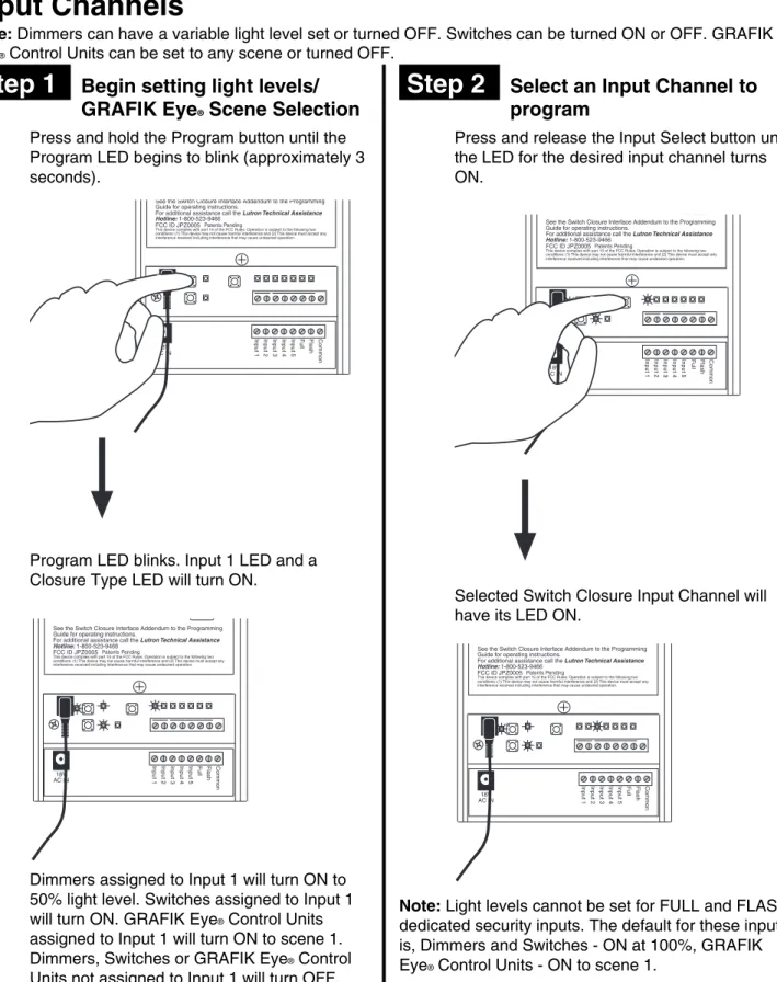
Step 1
Begin setting light levels/
GRAFIK Eye
®Scene Selection
18V AC IN
Full Flash Input 1 Input 2 Input 3 Input 4 Input 5 Common See the Switch Closure Interface Addendum to the Programming Guide for operating instructions.
For additional assistance call the Lutron Technical Assistance
Hotline: 1-800-523-9466
FCC ID JPZ0005
This device complies with part 15 of the FCC Rules. Operation is subject to the following two conditions: (1) This device may not cause harmful interference and (2) This device must accept any interference received including interference that may cause undesired operation.
Patents Pending
18V AC IN
Full Flash Input 1 Input 2 Input 3 Input 4 Input 5 Common
In ut 5 See the Switch Closure Interface Addendum to the Programming Guide for operating instructions.
For additional assistance call the Lutron Technical Assistance
Hotline: 1-800-523-9466
FCC ID JPZ0005
This device complies with part 15 of the FCC Rules. Operation is subject to the following two conditions: (1) This device may not cause harmful interference and (2) This device must accept any interference received including interference that may cause undesired operation.
Patents Pending
Program LED blinks. Input 1 LED and a Closure Type LED will turn ON.
Dimmers assigned to Input 1 will turn ON to 50% light level. Switches assigned to Input 1 will turn ON. GRAFIK Eye® Control Units
assigned to Input 1 will turn ON to scene 1. Dimmers, Switches or GRAFIK Eye® Control
Step 2
Select an Input Channel to
program
Selected Switch Closure Input Channel will have its LED ON.
See the Switch Closure Interface Addendum to the Programming Guide for operating instructions.
For additional assistance call the Lutron Technical Assistance
Hotline: 1-800-523-9466
FCC ID JPZ0005
This device complies with part 15 of the FCC Rules. Operation is subject to the following two conditions: (1) This device may not cause harmful interference and (2) This device must accept any interference received including interference that may cause undesired operation.
Patents Pending
18V AC IN
Full Flash Input 1 Input 2 Input 3 Input 4 Input 5 Common
18V AC IN
Full Flash Input 1 Input 2 Input 3 Input 4 Input 5 Common See the Switch Closure Interface Addendum to the Programming Guide for operating instructions.
For additional assistance call the Lutron Technical Assistance
Hotline: 1-800-523-9466
FCC ID JPZ0005
This device complies with part 15 of the FCC Rules. Operation is subject to the following two conditions: (1) This device may not cause harmful interference and (2) This device must accept any interference received including interference that may cause undesired operation.
Patents Pending
Note: Light levels cannot be set for FULL and FLASH dedicated security inputs. The default for these inputs is, Dimmers and Switches - ON at 100%, GRAFIK Eye® Control Units - ON to scene 1.
Press and hold the Program button until the Program LED begins to blink (approximately 3 seconds).
Press and release the Input Select button until the LED for the desired input channel turns ON.
Section 3 - Expanding
Y
our System
Adding a Switch Closure Interface
To set the light level for another Input
Channel, press the Input Select button to turn that channel's LED ON.
18V AC IN
Full Flash Input 1 Input 2 Input 3 Input 4 Input 5 Common See the Switch Closure Interface Addendum to the Programming Guide for operating instructions.
For additional assistance call the Lutron Technical Assistance
Hotline: 1-800-523-9466
FCC ID JPZ0005
This device complies with part 15 of the FCC Rules. Operation is subject to the following two conditions: (1) This device may not cause harmful interference and (2) This device must accept any interference received including interference that may cause undesired operation.
Patents Pending
Step 4
Select next Input Channel to
program
Step 3
Set light levels/select GRAFIK
Eye
®scenes
Go to any assigned Dimmer (which will be ON at 50%). Adjust this Dimmers programmed light level for the selected SCENE button using the dimming rocker, or turn the Dimmer OFF if it is to be turned OFF when this Input Channel is activated.
Adjust light levels Turn OFF
OR
LUTRON
Go to any assigned GRAFIK Eye® Control
Unit (which will be ON at scene 1). Select from pre-programmed scenes (1 through 4) by turning that scene ON or select OFF if it is to be turned OFF when this Input Channel is activated.
Go to any assigned Switch (which will be ON). Turn the Switch OFF if it is to be turned OFF when this Input Channel is activated.
Selected Switch Closure Input Channel will have its LED ON.
18V AC IN
Full Flash Input 1 Input 2 Input 3 Input 4 Input 5 Common
In ut 5 See the Switch Closure Interface Addendum to the Programming Guide for operating instructions.
For additional assistance call the Lutron Technical Assistance
Hotline: 1-800-523-9466
FCC ID JPZ0005
This device complies with part 15 of the FCC Rules. Operation is subject to the following two conditions: (1) This device may not cause harmful interference and (2) This device must accept any interference received including interference that may cause undesired operation.
Section 3 - Expanding
Y
our System
Step 5
Complete setting light levels/
GRAFIK Eye
®Scene Selection
Adding a Switch Closure Interface
Press the Program button until the blinking Program LED turns OFF (approximately 3 seconds).
All Input LEDs will flutter for a few seconds when completing.
18V AC IN
Full Flash Input 1 Input 2 Input 3 Input 4 Input 5 Common See the Switch Closure Interface Addendum to the Programming Guide for operating instructions.
For additional assistance call the Lutron Technical Assistance
Hotline: 1-800-523-9466
FCC ID JPZ0005
This device complies with part 15 of the FCC Rules. Operation is subject to the following two conditions: (1) This device may not cause harmful interference and (2) This device must accept any interference received including interference that may cause undesired operation.