NEC Corporation has prepared this document for use by its employees and customers. The information contained herein is the property of NEC Corporation and shall not be reproduced without prior written approval of NEC Corporation.
All other brand names and product names referenced in this document are trademarks or registered trademarks of their respective companies.
Copyright 2014
NEC Corporation of America 6535 N. State Highway 161
Irving, TX 75039-2402 Communications Technology Group
___________________________________________________________________________________
SL1100
Chapter 1 Introduction
Section 1
General Overview... 1-1
Section 2
Common Terms... 1-1
Chapter 2 General Information
Section 1
Voice Over IP ... 2-1
Chapter 3 IP Networking
Section 1
Introduction ... 3-1
Section 2
IP Trunks... 3-1
2.1
Configure IP Trunks ... 3-2
Chapter 4 General IP Configuration
Section 1
Introduction ... 4-1
Section 2
Network Addressing Overview ... 4-2
2.1
IP Address ... 4-2
2.2
Subnet Mask ... 4-2
2.3
DHCP ... 4-3
Section 3
Configuration Examples... 4-3
3.1
Example Configuration 1 - Existing Network with Static Addressing ... 4-3
Section 4
Testing the NEC SL1100 Network Connection ... 4-6
Chapter 5 Programming
Section 1
Before You Start Programming ... 5-1
Section 2
How to Enter Programming Mode... 5-2
Section 3
How to Exit Programming Mode ... 5-3
Section 4
Using Keys to Move Around in the Programs ... 5-4
Section 5
Programming Names and Text Messages... 5-5
Section 6
Using Softkeys For Programming... 5-6
Section 7
What the Softkey Display Prompts Mean ... 5-7
Section 8
Programs ... 5-7
10-12 : CPU Network Setup ... 5-8 10-13 : In-DHCP Server Setup ... 5-11 10-14 : Managed Network Setup ... 5-12 10-15 : Client Information Setup ... 5-13 10-16 : Option Information Setup ... 5-14 10-19 : VoIP DSP Resource Selection ... 5-18 10-62 : NetBIOS Setting ... 5-19 10-63 : DHCP Client Setting ... 5-20
Program 20 : System Option Setup ... 5-21
15-05 : IP Telephone Terminal Basic Data Setup ... 5-21 84-09 : VLAN Setup ... 5-25 84-10 : ToS Setup ... 5-26
Chapter 6 Network Design Considerations
Section 1
Introduction ... 6-1
Section 2
QoS... 6-1
2.1
QoS Definitions ... 6-1
2.2
Voice Quality Improvements ... 6-3
2.3
Types of Classifications for Traffic for QoS ... 6-4
Section 3
Internet Based Connections (xDSL, Cable, etc.) ... 6-6
Section 4
Firewalls and NAT ... 6-7
4.1
Understanding the Infrastructure ... 6-7
4.2
Firewall Integration ... 6-8
4.3
Virtual Private Network (VPN) Tunnelling ... 6-9
Section 5
CODEC and Bandwidth ... 6-11
5.1
CODECs ... 6-11
5.2
Bandwidth ... 6-13
Section 6
Quality of Service (QoS) Implementation ... 6-13
6.1
Prioritization ... 6-14
6.2
Layer 2 QoS (802.1pq) ... 6-16
6.3
Layer 3 QoS ... 6-20
6.4
IP Precedence ... 6-22
6.5
Diffserv (Differentiated Service) ... 6-23
6.6
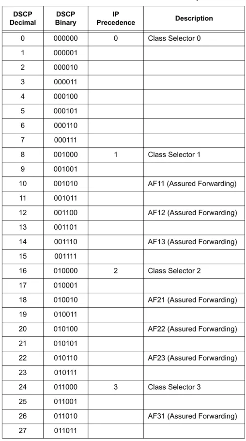
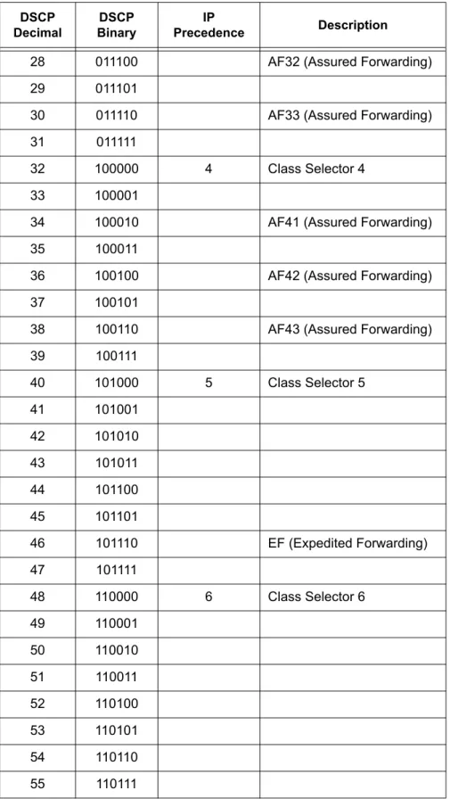
Comparison of IP Precedence and Diffserv Values ... 6-24
6.7
Programming QoS in the NEC SL1100 System ... 6-27
6.7.1 Marking Voice Traffic - Program 84-10-XX ...6-276.7.3 Configuring Diffserv ... 6-27 6.7.4 Configuration Examples for Classification and Queuing ... 6-29
Section 7
Port Designations ... 6-31
Chapter 7 SIP Trunking
Section 1
VoIP... 7-1
Section 2
IP Networking... 7-1
Section 3
SIP Trunking... 7-2
3.1
Introduction ... 7-2
3.1.1 SIP Trunking Requirements ... 7-3 3.1.2 SIP Trunking Setup ... 7-4Section 4
SIP Trunk Overview... 7-5
4.1
General Information ... 7-5
4.2
Supported Protocols ... 7-5
4.3
Supported SIP Methods ... 7-6
4.4
Supported SIP Trunking Options ... 7-6
4.5
Supported CODEC ... 7-7
Section 5
Supported SIP Trunking Functions ... 7-7
5.1
Address Resolution ... 7-7
5.2
Authentication Process ... 7-7
5.3
Caller ID ... 7-8
5.4
Carrier Support ... 7-8
5.5
Early Media ... 7-8
5.8
Quality of Service (QoS) ... 7-9
5.9
Registration ... 7-9
5.9.1 Registration Process ...7-9 5.9.2 Registration Recover Process ...7-9Section 6
SIP Trunk Programming ... 7-10
6.1
SIP Trunk Basic Setup ... 7-10
6.2
IP DSP Resource ... 7-13
6.3
SIP Authentication Information ... 7-14
6.4
SIP Caller ID ... 7-16
6.5
SIP CODEC Trunk ... 7-17
6.6
SIP DNS Setup ... 7-23
6.7
SIP NAPT Router Setup ... 7-23
6.8
SIP System Interconnection Setup ... 7-24
6.9
SIP Protocol ... 7-24
6.10 SIP Server Information Setup ... 7-25
6.11 SIP Registrar Setup ... 7-26
6.12 SIP Server Status ... 7-27
6.13 SIP Trunk Registration Information Setup ... 7-28
6.14 SIP UPnP ... 7-28
Chapter 8 DHCP Client
Section 1
DHCP Client ... 8-1
Section 2
DHCP Server Configuration Example ... 8-5
Chapter 9 IP Multiline Station (SIP)
Section 2
IP to TDM Conversion ... 9-1
2.1
DR700 IP Multiline Telephones ... 9-2
2.2
Conditions ... 9-3
2.3
LAN Connection ... 9-4
Section 3
Providing Power ... 9-5
3.1
Local Power ... 9-5
3.2
Power Over Ethernet (PoE) ... 9-5
Section 4
Peer-to-Peer ... 9-6
Section 5
Programming ... 9-6
5.1
Music on Hold ... 9-7
Section 6
Configuration Examples ... 9-7
6.1
Example Configuration 1 - Static IP Addressing, One LAN ... 9-8
6.2
Example Configuration 2 - Dynamic IP Addressing, One LAN ... 9-9
6.3
Example Configuration 3 - Static IP Addressing, Routed WAN ... 9-11
Section 7
IP Phone Programming Interface ... 9-12
Section 8
DHCP Server Configuration ... 9-12
Section 9
Configuring Quality of Service ... 9-13
9.1
Layer 2 Priority Control ... 9-14
9.1.1 Programming Layer 2 Priority Control ... 9-149.2
Layer 3 (ToS) Priority Control ... 9-15
9.2.1 Programming Layer 3 Priority Control ... 9-15Section 12
Firmware Upgrade Procedure... 9-16
12.1 Manually Upgrading Firmware ... 9-16
12.2 Checking the Firmware Version ... 9-17
12.3 Upgrading Automatically ... 9-17
Section 13
IP Station (SIP Multiline Telephone)... 9-18
13.1 Description ... 9-18
13.2 IP Addressing ... 9-20
13.3 IP Phone Registration Modes ... 9-20
13.4 General IP Configuration ... 9-23
13.5 VLANs ... 9-23
13.5.1 Logging In on the PC ...9-24 13.5.2 Tagging Voice Packets Using IP Phone ...9-26 13.5.3 Tagging Data Packets Using IP Phone ...9-28 13.5.4 Entering VLAN Settings by Phone (Voice Packets Only) ...9-31 13.5.5 Entering VLAN Settings for PC Port by Phone(Data Packets Only) ...9-31
13.6 ToS Settings (Layer 3 QoS) ... 9-32
13.7 Bandwidth ... 9-40
13.8 Some Network Considerations ... 9-43
13.9 Guide to Feature Programming ... 9-48
13.10 SIP MLT Quick Startup Guide ... 9-59
13.10.1 Plug and Play ...9-59 13.10.2 Automatic Registration ...9-63 13.10.3 Manual Registration ...9-6713.11 IP Phone Relocation ... 9-69
Section 14
NAPT ... 9-71
14.1 Introduction ... 9-71
14.2 SL1100 Requirements ... 9-73
14.2.1 Main Software ... 9-73 14.2.2 Hardware ... 9-73 14.2.3 Capacity ... 9-7314.3 Installation ... 9-73
14.3.1 Settings for terminals ... 9-73Section 15
Conditions ... 9-75
Section 16
Restrictions – Static NAT... 9-75
Section 17
Minimum Required Programming ... 9-76
Chapter 10 IP Single Line Telephone
Section 1
Introduction... 10-1
Section 2
Programming ... 10-3
2.1
Card Setup ... 10-3
2.2
Configure VoIPDB Networking Information ... 10-4
2.2.1 VoIPDB (DSP) Basic Setup ... 10-4 2.2.2 VoIP ToS Setup ... 10-5 2.2.3 SIP Peer to Peer ... 10-5 2.2.4 IP Extension Numbering ... 10-6 2.2.5 SIP Extension CODEC Information ... 10-6 2.2.6 SIP Extension Basic Information Setup ... 10-10 2.2.7 IP Phone Configuration ... 10-11 2.2.8 NAT Mode for Standard SIP terminal (Version 4.0 or higher) ... 10-12Chapter 11 NAPT
Section 1
NAPT ... 11-1
1.1
Introduction ... 11-1
1.2
SL1100 Requirements ... 11-3
1.2.1 Main Software ...11-3 1.2.2 Hardware ...11-3 1.2.3 Capacity ...11-3 1.2.4 License ...11-31.3
Installation ... 11-3
1.3.1 Settings for terminals ...11-3Section 2
Conditions ... 11-5
Section 3
Restrictions – Static NAT ... 11-5
Section 4
Minimum Required Programming ... 11-6
Chapter 12 All DSP Busy Indication
Section 1
Introduction ... 12-1
Section 2
Service Conditions... 12-2
Section 3
Related Features ... 12-3
Section 4
Guide to Feature Programming ... 12-3
Chapter 13 SL Net
Section 1
Introduction ... 13-1
Section 2
System Capacity ... 13-3
Section 3
Network Requirements... 13-4
Section 4
Quality of Service Settings (QOS)... 13-5
Section 5
IP Precedence ... 13-5
Section 6
Diffserv ... 13-7
6.1
Conditions ... 13-8
Section 7
Guide to Feature Programming... 13-12
Section 8
Programming Examples... 13-36
8.1
Basic SL Net Setup ... 13-36
Section 9
List of Supported Features in a Networked System... 13-42
___________________________________________________________________________________
SL1100
Figure 3-1 Example of SL1100 IP Network Configuration ... 3-2 Figure 4-1 Example Configuration 1 - Existing Network with Static IP Address ... 4-4 Figure 4-2 Example Configuration 1 - Adding the NEC SL1100 KSU to the Network ... 4-5 Figure 4-3 Testing the Network Connection ... 4-6 Figure 6-1 Layer 2 Diagram (802.1Q) ... 6-5 Figure 6-2 Virtual Private Network (VPN) Example ... 6-10 Figure 6-3 Network Bottleneck Example ... 6-14 Figure 6-4 Voice and Data Network Implementation ... 6-15 Figure 6-5 Priority Queuing on Voice and Data Networks ... 6-16 Figure 6-6 Protocol Structure for Layer 2 QoS ... 6-17 Figure 6-7 Layer 3 QoS Example ... 6-20 Figure 6-8 Common Network with Cisco Router ... 6-29 Figure 7-1 Common IP Network using NEC SL1100 SIP Trunk ... 7-3 Figure 8-1 DHCP - Set Predefined Options ... 8-5 Figure 8-2 DHCP - Predefined Options and Values ... 8-6 Figure 8-3 DHCP - Scope Options ... 8-7 Figure 8-4 DHCP - Data Entry for 1st DHCP Server ... 8-8 Figure 9-1 DR700 IP Telephone (ITL) ... 9-2 Figure 9-2 Typical Network IP Connection ... 9-4 Figure 9-3 Example Configuration 1 - Static IP Addressing, One LAN ... 9-8 Figure 9-4 Example Configuration 2 - Dynamic IP Addressing, One LAN ... 9-10 Figure 9-5 Example Configuration 3 - Static IP Addressing, Routed WAN ... 9-11 Figure 9-6 DR700 Encryption ...9-22 Figure 9-7 Log In to IP Phone ... 9-25
Figure 9-9 VLAN Mode ... 9-27 Figure 9-10 VLAN ID ... 9-27 Figure 9-11 VLAN Priority ... 9-27 Figure 9-12 PC Port Settings Window ... 9-28 Figure 9-13 Port VLAN Mode ... 9-29 Figure 9-14 Port VLAN ID ... 9-29 Figure 9-15 Port VLAN Priority ... 9-29 Figure 9-16 Save Network Settings ... 9-30 Figure 9-17 Save Confirmation Window ... 9-30 Figure 9-18 84-10: ToS Setup ... 9-34 Figure 9-19 SIP MLT Basic Setup ... 9-36 Figure 9-20 Type of Service Window ... 9-38 Figure 9-21 RTP - Voice Packets ... 9-39 Figure 9-22 SIP - Signalling Packets ... 9-39 Figure 9-23 NEC SL1100 Network Example No. 1 ... 9-44 Figure 9-24 NEC SL1100 Network Example No. 2 ... 9-45 Figure 9-25 IP System Operation Setup ... 9-47 Figure 9-26 System Data 10-12: CD CP00 Network Setup ... 9-59 Figure 9-27 System Data 84-26: VoIPDB Basic Setup (DSP) ... 9-60 Figure 9-28 System Data 11-02: Extension Numbering ... 9-61 Figure 9-29 IP Phone List ... 9-61 Figure 9-30 IP Phone List ... 9-63 Figure 9-31 DR700 Server Information Setup ... 9-64 Figure 9-32 Automatic Registration Basic Setup ... 9-64 Figure 9-33 Automatic Registration Personal ID Index ... 9-64 Figure 9-34 Automatic Registration User Name and Password Assignment ... 9-65 Figure 9-35 DR700 Server Information Setup ... 9-67 Figure 9-36 NAPT Configuration Example ... 9-72
Figure 13-2 IP Precedence ... 13-6 Figure 13-3 Setup Example ... 13-8 Figure 13-4 Programming Example ... 13-36
___________________________________________________________________________________
SL1100
Table 1-1 Common Terms and Associated Abbreviations ... 1-1 Table 2-1 VoIP Specifications ... 2-1 Table 5-1 Keys for Entering Data ... 5-4 Table 5-2 Keys for Entering Names ...5-5 Table 5-3 Softkey Display Prompts ...5-7 Table 6-4 Type of Service Field (IP Precedence - i Ref. REC 1349) ...6-22 Table 6-5 Diffserv Parameters ...6-23 Table 6-6 IP Precedence and Diffserv Values Comparison ...6-25 Table 6-7 Cisco Router Configuration Example ...6-30 Table 9-1 IP Phone Programming Options User Menu ... 9-12 Table 9-2 DR700 Supported Encryption ...9-22 Table 9-3 Common IP Precedence/Diffserv Values and Hexadecimal Equivalent ...9-37 Table 9-4 IP Phone Relocation ...9-70 Table 12-1 Alarm Types ... 12-1 Table 13-1 Bandwidth per VoIP Call ... 13-5 Table 13-2 Diffserv Parameters ...13-7
Intr
oduction
1
Introduction
S
ECTION1
GENERAL OVERVIEW
This manual provides information for networking for the NEC SL1100 system.
S
ECTION2
COMMON T
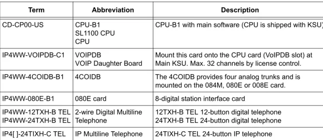
ERMSThe following terms and the associated abbreviations or alternate nomenclature may be found throughout this document.
Table 1-1 Common Terms and Associated Abbreviations
Term Abbreviation Description
CD-CP00-US CPU-B1
SL1100 CPU CPU
CPU-B1 with main software (CPU is shipped with KSU)
IP4WW-VOIPDB-C1 VOIPDB
VOIP Daughter Board
Mount this card onto the CPU card (VoIPDB slot) at Main KSU. Max. 32 channels by license control. IP4WW-4COIDB-B1 4COIDB The 4COIDB provides four analog trunks and is
mounted on the 084M, 080E or 008E card. IP4WW-080E-B1 080E card 8-digital station interface card
IP4WW-12TXH-B TEL IP4WW-24TXH-B TEL
2-wire Digital Multiline Telephone
12TXH-B TEL 12-button digital telephone 24TXH-B TEL 24-button digital telephone IP4[ ]-24TIXH-C TEL IP Multiline Telephone 24TIXH-C TEL 24-button IP telephone
Gener
a
l Inf
o
rma
tion
2
General Information
S
ECTION1
V
OICE OVER IPVoice over IP (VoIP) is a technology that converts speech into data packets and transmits these packets over TCP/IP networks. The
technology also facilitates compression and silence suppression to reduce network bandwidth demands.
As most organizations already have existing data networks in place, considerable cost savings can be achieved by utilizing spare bandwidth on these networks for voice traffic.
NEC SL1100 supports the use of IP Phones. These telephones provide the same functionality as a multiline telephone but use the data network rather then the traditional telecoms infrastructure. This can reduce costs and allow the use of NEC SL1100 telephones in locations that would not normally be supported by multiline telephones.
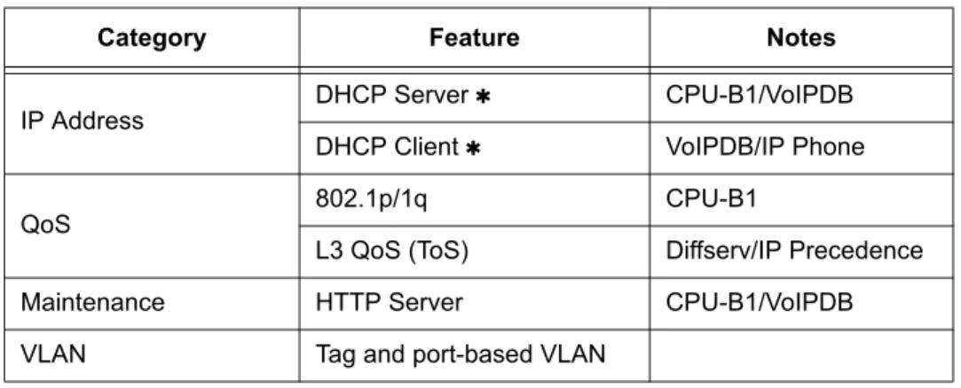
Table 2-1 VoIP Specifications lists the specifications for various aspects of NEC SL1100 VoIP system.
Table 2-1 VoIP Specifications
Category Feature Notes
IP Address DHCP Server CPU-B1/VoIPDB
DHCP Client VoIPDB/IP Phone
QoS 802.1p/1q CPU-B1
L3 QoS (ToS) Diffserv/IP Precedence
Maintenance HTTP Server CPU-B1/VoIPDB
VoCoder G.711 µ-law/A-law G.729a G.722 G.723 G.726 iLBC
Jitter Buffer Size Set by system programming RTP Length Set by system programming Echo Canceller Tail
Size
Set by system programming Level Adjustment Set by system programming
IP Phone SIP Phone SIP Phone
SIP Trunk SIP Trunk Maximum 32 Trunks
DHCP Server and DHCP Client cannot be used at the same time. When the DHCP Server is enabled the DHCP Client function cannot be activated. When the VoIPDB is installed, the CPU-B1 is no longer active, all IP connections go through the VoIPDB.
Table 2-1 VoIP Specifications (Continued)
IP Netw
or
king
3
IP Networking
S
ECTION1
INTRODUCTION1
IP Networking uses VoIP technology to connect two or more telephone systems together. This allows calls to be made between sites without using the public telephone network. This saves considerable money, and makes communication between sites much easier.
S
ECTION2
IP TRUNKS
The SIP Trunks method of networking allows connection to SIP devices. This could be a PBX system or a third-party product. When using SIP, the feature set is limited and the advanced networking features cannot be used.
Refer to SIP Trunking for a a detailed description of SIP trunking and for set up instructions.
To set up IP trunks:
1. Connect the system to the Data Network. (Refer to General IP Configuration for detailed instructions.)
2. Configure the IP trunks. 3. Configure the SIP information. 4. Configure the F-Route.
1. The voice quality of VoIP is dependent on variables such as available bandwidth, network latency and Quality of Service (QoS) initiatives, all of which are controlled by the network and internet service providers. Because these variables are not in NEC control, it cannot guarantee the performance of the user’s IP-based remote voice solution. Therefore, NEC recommends connecting VoIP equipment through a local area network using a Private IP address.
2.1
Configure IP Trunks
When installing a VoIP daughter board in the NEC SL1100 system, external line ports are allotted in accordance with the number of Licensed ports for the particular IP Application.
The NEC SL1100 system now has the required information about the remote destinations and the SIP configuration is complete. The only remaining task is to configure F-Route to route calls to remote destinations via the IP trunks. F-Route configuration is discussed in detail in the Automatic Route Selection (ARS) feature in the NEC SL1100 Programming Manual.
Gener
a
l IP Conf
igur
at
ion
4
General IP Configuration
S
ECTION1
INTRODUCTION
The NEC SL1100 system uses IP for various applications, including:
System Programming
Voice Over IP
This section describes the procedure for connecting the NEC SL1100 system to an existing data network and configuring TCP/IP. This is the first step in implementing VoIP and other IP applications.
Enhancements
With SL1100 Version 1200 (V1.20) and VoIP daughter board installed, half duplex connections are not supported. For troubleshooting
purposes, a managed switch capable of port mirroring is required to capture packet data from the SL1100 VoIPDB Ethernet port.
S
ECTION2
NETWORK ADDRESSING OVERVIEW
Before connecting the system to a data network, it is necessary to obtain the relevant IP Addressing information. This information is supplied by the IT Manager or Network Administrator at the customer site.
2.1
IP Address
All equipment/devices used in the LAN setup must have an IP address assignment. An IP address assigns a unique address for each device. There are two types of IP addresses: Private and Global. A Private IP address is not accessible through the internet; a Global IP address can be accessed through the internet.
In most cases, a Private address is used, as LAN devices are not usually directly connected to the internet. Private addresses are usually taken from the following ranges:
Class A 10.0.0.0 ~ 10.22.255.255 Class B 172.16.0.0. ~ 172.31.255.255 Class C 192.168.0.0 ~ 192.168.255.255
A Public address is normally only used when a device is directly connected to the internet. This is unlikely in the case of the equipment. If Public addressing is used, the numbers are normally allocated by an ISP.
2.2
Subnet Mask
As the IP address includes information to identify both the network and the final destination, the Subnet Mask sets apart the network and destination information. The default subnet masks are:
Class A 255.0.0.0 Class B 255.255.0.0 Class C 255.255.255.0
The Subnet Mask is made up of four groups of numbers. When a group contains the number 255, the router ignores or masks that group of numbers in the IP address as it is defining the network location of the final destination.
For example, if the IP address is: 172.16.0.10 and the Subnet Mask used is Class B (255.255.0.0), the first two groups of numbers (172.16) are ignored once they reach the proper network location. The next two groups (0.10) are the final destination within the LAN to which the connection is to be made.
For sub-netted networks, the subnet mask may be different from the
default subnet masks listed above.
2.3
DHCP
Dynamic Host Configuration Protocol (DHCP) assigns a dynamic IP address. Network control may be easier with DHCP as there is no need to assign and program individual IP addresses for the LAN equipment. To use a dynamic IP address, a DHCP server must be provided. The SL1100 can be configured to be the DHCP server for the customers network. Before the DHCP server in the SL1100 can be enabled, the DHCP client function must first be disabled. When equipment, which is connected to the LAN (the DHCP client), is requesting an IP address, it searches the DHCP server.
When the request for an address is recognized, the DHCP server assigns an IP address, Subnet mask, and the IP address of the router, based on NEC SL1100 system programming.
S
ECTION3
CONFIGURATION EXAMPLES
The following configuration examples illustrate a typical network configuration for an existing network that uses a static address and a typical configuration for a new network that uses a dynamic address.
3.1
Example Configuration 1 - Existing Network with Static
Addressing
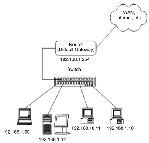
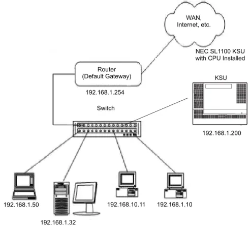
Figure 4-1 Example Configuration 1 - Existing Network with Static IP Address on page 4-4 shows a typical network configuration that uses Static IP
Addressing.
Each client device has a manually assigned IP address in the 192.168.1.0/24 network (i.e., 192.168.1.1 to 192.168.1.254 with a subnet mask of
255.255.255.0). They also have a default gateway address configured (192.168.1.254) this allows the device to route packets to destinations that exist outside of their own LAN.
Assume that a NEC SL1100 is added to the existing data network. The Network Administrator (or IT Manager) should provide the following: IP Address (for the CPU-B1)
IP Addresses (for the VoIP daughter board)
Subnet Mask
Default Gateway A spare switch
First, program the NEC SL1100:
192.168.1.200
255.255.255.0
Figure 4-1 Example Configuration 1 - Existing Network with Static IP Address Router (Default Gateway) WAN, Internet, etc. 192.168.1.254 192.168.1.50 192.168.1.32 192.168.10.11 192.168.1.10 Switch
Now connect the CPU-B1/VoIPDB Ethernet Port to the switch port, using a standard Cat-5 patch cable. The NEC SL1100 is now configured on the network and should be accessible by other devices on the network. Refer to Figure 4-2 Example Configuration 1 - Adding the NEC SL1100 KSU to the Network.
Figure 4-2 Example Configuration 1 - Adding the NEC SL1100 KSU to the Network
Router (Default Gateway) WAN, Internet, etc. 192.168.1.254 192.168.1.50 192.168.1.32 192.168.10.11 192.168.1.10 NEC SL1100 KSU with CPU Installed
192.168.1.200 Switch
S
ECTION4
T
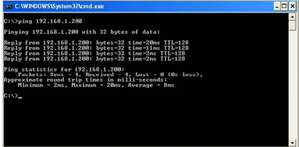
ESTING THE NEC SL1100 NETWORK CONNECTIONTo test the NEC SL1100 network connection, it is possible to use the ICMP (Internet Control Message Protocol) Ping command. This basically sends a small amount of data from one device to another and then waits for a reply. This test confirms that the IP addressing and physical connection are good. To perform this test, from a
Windows PC: 1. Click Start. 2. Click Run... .
3. In the Open dialogue box, enter command. 4. Click OK. A Command prompt window opens. 5. Type ping 192.168.1.200.
Figure 4-3 Testing the Network Connection shows that the NEC SL1100 system has replied to the Ping request – this indicates that the NEC SL1100 system is correctly connected to the network.
Pr
og
ra
mming
5
Programming
S
ECTION1
BEFORE Y
OU START PROGRAMMINGThis chapter provides you with detailed information about the NEC SL1100 program blocks that may be required to connect the NEC SL1100 to a data network and to configure the VoIP function. The configuration and
programming examples, found in the earlier chapters, can be a useful reference when programming the data.
When using this chapter, note that the information on each program is subdivided into the following headings:
Description describes what the program options control. The Default Settings for each program are also included. When you first install the system, it uses the Default Setting for all programs. Along with the Description are the Conditionswhich describe any limit or special consideration that may applies to the program.
The reverse type (white on black) just beneath the Description heading is the program access level. You can use only the program if your access level meets or exceeds the level the program requires. Refer to Section 2 How to Enter Programming Mode on page 5-2 for a list of the system access levels and passwords.
Feature Cross Reference provides you with a table of all the features affected by the program. You should keep the referenced features in mind when you change a program. Customizing a feature may have an effect on another feature that you did not intend.
Telephone Programming Instructions shows how to enter the program data into system memory. For example:
To enter the programming mode: 1. 15-07-01
Dial 150701 from the telephone dial pad. See the message 15-07-01 TEL on the first line of the telephone display. This indicates the program number (15-07), item number (01), and that the options are being set for the extension.
The second row of the display KY01 = *01 indicates that Key 01 is being programmed with the entry of *01. The third row allows you to move the cursor to the left or right, depending on which arrow is pressed.
To learn how to enter the programming mode, refer to Section 2 How to Enter Programming Mode below.
S
ECTION2
HOW TO ENTER PROGRAMMING MODE
To enter programming mode:1. Go to any working display telephone.
In a newly installed system, use extension (port 1). 2. Do not lift the handset.
3. Press Speaker. 4. ## . 15-07-01 TEL KY01 = *01
Password5. Dial the system password + Hold.
Refer to the following table for the default system passwords. To change the passwords, use 90-02: Programming Password Setup.
S
ECTION3
HOW TO EXIT PROGRAMMING MODE
To exit the programming mode:To exit programming mode, first exit the programming options mode.
1. Press Mute to exit program options, if needed.
2. Press Speaker. If changes were made to the system programming, Saving System Data is displayed.
3. When completed, the display shows Complete Data Save and exits the telephone to idle.
To save a customer database, a blank Compact Flash (CF) is required. Insert the CF into the CD-CP00-US and, using Program 90-03, save the software to the Compact Flash. (Program 90-04 is used to reload the customer data if necessary.) Note that a Compact Flash can hold only one customer database. Each database to be saved requires a separate card.
Password User
Name Level Programs at this Level
12345678 sltech 2 (IN) Installation(IN): All programs in this section not listed for MF, SA, and SB
0000 ADMIN1 3 (SA) System Administrator - Level 1 (SA):
10-01,10-02,10-12,10-13,10-14,10-15,10-16,10-17,10- 18,10-23,10-24,10-25,10-28,10-29,10-45,12-02,12- 03,12-04,12-08,15-01,15-07,15-09,15-10,15-11,20- 16,20-34,21-07,21-14,22-04,22-11,22-17,25-08,30- 03,30-04,32-02,45-02,84-22,90-03,90-04,90-06,90-07,90-19,90-57,90-58,90-59,90-65
9999 ADMIN2 4 (SB) System Administrator - Level 2 (SB): 13-04, 13-05, 13-06, 13-11, 15-14, 21-20
Program Mode Base Service OP1 OP2
S
ECTION4
USING KEYS TO MOVE AROUND IN THE PROGRAMS
Once you enter the programming mode, use the keys in the following chart to enter data, edit data and move around in the menus.
Table 5-1 Keys for Entering Data
Keys for Entering Data
Use this key... When you want to... 0~9 and Enter data into a program.
Hold Complete the programming step you just made (e.g., pressing Enter on a PC keyboard). When a program entry displays, press Hold to bypass the entry without changing it.
Clear/Back Delete the entry to the left (e.g., pressing Backspace on a PC keyboard). Flash Delete or clear all characters to the right of the cursor.
Mute Exit one step at a time from the program window currently being viewed. For example, if programming item 5 in 15-03, pressing Mute allows you to enter a new option in program 15-03. Pressing Mute again allows you to select a new program in the 15-XX series. Pressing Mute a third time allows you to enter a new program beginning with 1. Pressing Mute one last time brings you to the beginning program display, allowing you to enter any program number.
DND Switch between the different input data fields by pressing DND. The cursor moves up to the top row of the display. Pressing DND again moves the cursor back to the middle row.
Line Keys Use pre-programmed settings to help with the program entry. These settings vary between programs from LINE 1 = 0 (off) and LINE 2 = 1 (on) to preset values for timers where LINE 1 = 5, LINE 2 = 10, LINE 3 = 15, etc.
For programs with this option, the line key, which currently matches the programmed setting, lights steady.
The display can also indicate Softkey, which will allow you to select the values as well (-1 and +1 will step through these pre-programmed settings.)
Line Key 1 Program a pause into a Speed Dialing bin. Line Key 2 Program a recall/flash into a Speed Dialing bin. Line Key 3 Program an @ into a Speed Dialing bin.
VOL Scroll backward through a list of entry numbers (e.g., from extension etc.) or through entries in a table (e.g., Common Permit Table). If you enter data and then press this key, the system accepts the data before scrolling forward.
S
ECTION5
PROGRAMMING NAMES AND T
EXT MESSAGESSeveral programs (e.g., Program 20-16 : Selectable Display Messages) require you to enter text. Use the following chart when entering and editing text. When using the keypad digits, press the key once for the first character, twice for the second
character, etc. For example, to enter a C, press the key 2 three times. Press the key six times to display the lower case letter. The name can be up to 12 digits long.
VOL Scroll forward through a list of entry numbers (e.g., from extension etc.) or through entries in a table (e.g., Common Permit Table).
If you enter data and then press this key, the system accepts the data before scrolling backward.
Table 5-1 Keys for Entering Data (Continued)
Keys for Entering Data
Use this key... When you want to...
Table 5-2 Keys for Entering Names
Use this keypad digit . . . When you want to. . .
1 Enter characters:
1 @ [ ¥ ] ^ _ ` { | } Æ ¨ Á À Â Ã Ç É Ê ì ó
2 Enter characters: A-C, a-c, 2. 3 Enter characters: D-F, d-f, 3. 4 Enter characters: G-I, g-i, 4. 5 Enter characters: J-L, j-l, 5. 6 Enter characters: M-O, m-o, 6. 7 Enter characters: P-S, p-s, 7. 8 Enter characters: T-V, t-v, 8. 9 Enter characters: W-Z, w-z, 9. 0 Enter characters: 0 ! “ # $ % & ’ ( ) ô Õ ú ä ö ü Enter characters: + , - . / : ; < = > ? B E
S • ¢ £# # = Accepts an entry (only required if two letters on the same key are needed - ex: TOM). Pressing # again = Space. (In system programming mode, use the right arrow Softkey instead to accept and/or add a space.)
S
ECTION6
USING SOFTKEYS FOR PROGRAMMING
Each NEC SL1100 display telephone provides interactive Softkeys for intuitive feature access. The options for these keys will automatically change depending on where you are in the system programming. Simply press the Softkey located below the option you wish and the display will change accordingly.
Pressing the VOLUMEor VOLUMEwill scroll between the menus.
Clear/Back Clear the character entry one character at a time.
Flash Clear all the entries from the point of the flashing cursor and to the right.
Table 5-2 Keys for Entering Names
Use this keypad digit . . . When you want to. . .
_
Program Mode
Base Service OP1 OP2
S
ECTION7
WHAT THE SOFTKEY DISPLAY PROMPTS MEAN
When using a display telephone in programming mode, various Softkey options are displayed. These keys will allow you to easily select, scan, or move through the programs.
S
ECTION8
PROGRAMS
This sections describes the programs used to connect the NEC SL1100 to a data network and to configure the VoIP functions.
Table 5-3 Softkey Display Prompts
Softkey Display Prompts If you press this
Softkey . . . The system will. . . back Go back one step in the program display.
You can press VOLUME or VOLUME to scroll forward or backward through a list of programs.
Scroll down through the available programs.
Scroll up through the available programs. select Select the currently displayed program.
Move the cursor to the left.
Move the cursor to the right.-1 Move back through the available program options. +1 Move forward through the available program options.
Description
Use Program 10-12 : CPU Network Setup to setup the IP Address, Subnet-Mask, and Default Gateway addresses.
Caution! If any IP Address or NIC settings are changed, the system must be reset for the changes to take affect.
Program 10 : System Configuration Setup
10-12 : CPU Network Setup
Level:SA
Input Data
Item
No. Item Input Data Default Description
01 IP Address 0.0.0.0 ~ 126.255.255.254 128.0.0.1 ~ 191.254.255.254 192.0.0.1 ~ 223.255.255.254
192.168.0.10 Set for CPU.
02 Subnet Mask 128.0.0.0240.0.0.0 254.0.0.0 255.192.0.0 255.248.0.0 255.255.0.0 255.255.224.0 255.255.252.0 255.255.255.128 255.255.255.240 255.255.255.254 192.0.0.0 248.0.0.0 255.0.0.0 255.224.0.0 255.252.0.0 255.255.128.0 255.255.240.0 255.255.254.0 255.255.255.192 255.255.255.248 255.255.255.255 224.0.0.0 252.0.0.0 255.128.0.0 255.240.0.0 255.254.0.0 255.255.192.0 255.255.248.0 255.255.255.0 255.255.255.224 255.255.255.252
255.255.255.0 The setting of Subnet Mask is invalid when all Host Addresses are 0.
If the network section is: 0, 127, 128.0, 191.255, 192.0.0, 223.255.255
The setting of Subnet Mask is invalid.
03 Default
Gateway 0.0.0.0 ~ 126.255.255.254 128.0.0.1 ~ 191.254.255.254 192.0.0.1 ~ 223.255.255.254
04 Time Zone 0~24 (0 = -12 Hours and 24 = +12 Hours) +7
(-5 hours) Determine the offset from Greenwich Mean Time (GMT) time. Then enter its respective value. For example, Eastern Time (US and Canada) has a GMT offset of -5. The program data would then be 7 (0= -12, 1= -11, 2= -10, 3= -9, 4= -8, 5= -7, 6= -6, 7= -5, ……24= +12)
05 NIC
Interface 0 = Auto Detect1 = 100Mbps, Full-Duplex 2 = 100Mbps, Half-Duplex 3 = 10Mbps, Full-Duplex 4 = 10Mbps, Half-Duplex
0 NIC Auto Negotiate (CPU)
06 NAT Router
Setup 0 = No (Disable)1 = Yes (Enable) 0 If using an external NAT Router or not. 07 NAPT Router IP Address (Default Gateway [WAN]) 0.0.0.0 ~ 126.255.255.254 128.0.0.1 ~ 191.255.255.254 192.0.0.1 ~ 223.255.255.254
0.0.0.0 Set the IP address on the WAN side of router.
08 ICMP
Redirect 0= (Enable)1= (Disable) 0 When receiving ICMP redirect message, this
determines if the IP Routing Table updates automatically or not. 09 IP Address 0.0.0.0 ~ 126.255.255.254 128.0.0.1 ~ 191.255.255.254 192.0.0.1 ~ 223.255.255.254
172.16.0.10 Set for VoIPDB.
Input Data (Continued)
Item
Conditions
The system must be reset for these changes to take affect.
Feature Cross Reference
Voice Over Internet Protocol (VoIP)10 Subnet Mask 128.0.0.0 240.0.0.0 192.0.0.0 248.0.0.0 224.0.0.0252.0.0.0 254.0.0.0 255.0.0.0 255.128.0.0 255.192.0.0 255.224.0.0 255.240.0.0 255.248.0.0 255.252.0.0 255.254.0.0 255.255.0.0 255.255.128.0 255.255.192.0 255.255.224.0 255.255.240.0 255.255.248.0 255.255.252.0 255.255.254.0 255.255.255.0 255.255.255.128 255.255.255.192 255.255.255.224 255.255.255.240 255.255.255.248 255.255.255.252 255.255.255.254 255.255.255.255
255.255.0.0 Set for VoIPDB.
11 NIC Setup 0 = Auto Detect
1 = 100Mbps, Full-Duplex 2 = 100Mbps, Half-Duplex 3 = 10Mbps, Full-Duplex 4 = 10Mbps, Half-Duplex 5 = 1 Gbps, Full-Duplex 6 = 1 Gbps, Half-Duplex
0 Set for VoIPDB. Input Data (Continued)
Item
Description
Use Program 10-13 : In-DHCP Server Setup to setup the DHCP Server built into the CPU-B1 card.
Conditions
Program 10-13-01 cannot be enabled if Program 10-63-01 (DHCP Client Mode) is
enabled.
Feature Cross Reference
Voice Over Internet Protocol (VoIP)Program 10 : System Configuration Setup
10-13 : In-DHCP Server Setup
Level:SA
Input Data
Item
No. Item Input Data Default Description
01 DHCP Server
Mode 0 = Disable1 = Enable 0 Enable/Disable the built-in DHCP Server. 02 Lease Time Days 0~255 0 day Lease Time of the IP address to a
client.
Hour 0~23 0 hour Press Transfer to increment to the next setting data.
Minutes 1~59 30 minutes 05 Last DHCP Data 0 = Disable
1 = Enable
1 If 10-13-01 is enabled, Enable/ Disable DHCP resource.
Description
Use Program 10-14 : Managed Network Setup to set up the range of the IP address which the DHCP Server leases to a client.
Conditions None
Feature Cross Reference
Voice Over Internet Protocol (VoIP)Program 10 : System Configuration Setup
10-14 : Managed Network Setup
Level:SA
Item
No. Item Input Data Default
Related Program 01 The range of the IP address
to lease.
When Maximum has not been entered, the maximum value equals the minimum value. When Single is selected in 10-13-04, only 1 scope range can be entered.
When Divide Same Network is selected in 10-13-04, a maximum of 10 scope ranges can be entered. Minimum: 1.0.0.1 ~ 126.255.255.254 128.1.0.1 ~ 191.254.255.254 192.0.1.1 ~ 223.255.254.254 172.16.0.100 Maximum: 1.0.0.1 ~ 126.255.255.254 128.1.0.1 ~ 191.254.255.254 192.0.1.1 ~ 223.255.254.254 172.16.5.254
Description
Use Program 10-15 : Client Information Setup to set up the client information when the DHCP server needs to assign a fixed IP address to clients.
Conditions None
Feature Cross Reference
Voice Over Internet Protocol (VoIP)Program 10 : System Configuration Setup
10-15 : Client Information Setup
Level:SA
Input Data
Client Number 1~16
Item
No. Item Input Data Default
01 The IP address should be assigned out of the scope range set up in Program 10-14.
MAC: 00-00-00-00-00-00 ~ FF-FF-FF-FF-FF-FF 00-00-00-00-00-00 1.0.0.0 ~ 126.255.255.254 128.0.0.1 ~ 191.255.255.254 192.0.0.1 ~ 223.255.255.254 0.0.0.0
Description
Use Program 10-16 : Option Information Setup to set up the option given from the DHCP server to each client.
Program 10 : System Configuration Setup
10-16 : Option Information Setup
Level:SA
Input Data
Item
No. Item Input Data Default
01 Router
Set the Router IP address.
Code number 0~255 3 (Fixed)
IP address 0.0.0.0 ~ 126.255.255.254 128.0.0.1 ~ 191.255.255.254 192.0.0.1 ~ 223.255.255.254 0.0.0.0 02 DNS Server
Set IP address of DNS Server.
Code number 0~255 6 (Fixed)
IP address 0.0.0.0 ~ 126.255.255.254 128.0.0.1 ~ 191.255.255.254 192.0.0.1 ~ 223.255.255.254 0.0.0.0 03 TFTP Server
Set the name for the TFTP Server.
Code number 0~255 66 (Fixed)
Maximum 64 character strings No setting 05 MGC Code number 0~255 129 (Fixed)
IP address
0.0.0.0 ~ 126.255.255.254 128.0.0.1 ~ 191.255.255.254 192.0.0.1 ~ 223.255.255.254
172.16.0.10
06 Client Host Name Set the Client Host Name.
Code number 0~255 12 (Fixed)
Maximum 64 character strings No setting 07 DNS Domain Name
Set the DNS Domain Name.
Code number 0~255 15 (Fixed)
08 Download Protocol Set Download Protocol used for AutoConfig (for DT700 Series).
Code number 0~255 43 (Fixed)
Sub code number 163
1 = FTP 2 = HTTP
1 09 Encryption Information
Set an Encryption Information used for AutoConfig (for DT700 series).
Code number 0~255 43 (Fixed)
Sub code number 164
Maximum 128 character
strings No setting
10 FTP Server Address Set a FTP Server Address used for AutoConfig.
Code number 0~255 43 (Fixed)
Sub code number 141
IP address
0.0.0.0 ~ 126.255.255.254 128.0.0.1 ~ 191.255.255.254 192.0.0.1 ~ 223.255.255.254
0.0.0.0
11 Config File Name Set a File Name used for AutoConfig.
Code number 0~255 43 (Fixed)
Sub code number 151
Maximum 15 character strings No setting 12 Vender Class ID Code number 0~255 60 (Fixed)
Maximum 256 character strings
NECDT700 13 SNMP Server Code number 0~255 69 (Fixed)
IP address
0.0.0.0 ~ 126.255.255.254 128.0.0.1 ~ 191.255.255.254 192.0.0.1 ~ 223.255.255.254
0.0.0.0
14 POP3 Server Code number 0~255 70 (Fixed)
IP address
0.0.0.0 ~ 126.255.255.254 128.0.0.1 ~ 191.255.255.254 192.0.0.1 ~ 223.255.255.254
0.0.0.0
16 SIP Server (IP Address) Code number 0~255 120 (Fixed)
IP address
0.0.0.0 ~ 126.255.255.254 128.0.0.1 ~ 191.255.255.254 192.0.0.1 ~ 223.255.255.254
172.16.0.10 Input Data (Continued)
Item
17 SIP Server (Domain Name) Code number 0~255 120 (Fixed)
Maximum 20 character strings No setting 18 FTP Server Code number 0~255 141 (Fixed)
IP address
0.0.0.0 ~ 126.255.255.254 128.0.0.1 ~ 191.255.255.254 192.0.0.1 ~ 223.255.255.254
0.0.0.0
19 Config File Name Code number 0~255 151 (Fixed)
Maximum 15 character strings No setting 20 LDS Server 1 Code number 0~255 162 (Fixed)
IP address
0.0.0.0 ~ 126.255.255.254 128.0.0.1 ~ 191.255.255.254 192.0.0.1 ~ 223.255.255.254
0.0.0.0
21 LDS Server 2 Code number 0~255 162 (Fixed)
IP address
0.0.0.0 ~ 126.255.255.254 128.0.0.1 ~ 191.255.255.254 192.0.0.1 ~ 223.255.255.254
0.0.0.0
22 LDS Server 3 Code number 0~255 162 (Fixed)
IP address
0.0.0.0 ~ 126.255.255.254 128.0.0.1 ~ 191.255.255.254 192.0.0.1 ~ 223.255.255.254
0.0.0.0
23 LDS Server 4 Code number 0~255 162 (Fixed)
IP address
0.0.0.0 ~ 126.255.255.254 128.0.0.1 ~ 191.255.255.254 192.0.0.1 ~ 223.255.255.254
0.0.0.0
24 Next Server IP Address IP address
0.0.0.0 ~ 126.255.255.254 128.0.0.1 ~ 191.255.255.254 192.0.0.1 ~ 223.255.255.254
0.0.0.0
27 SIP Server Receive Port Code number 0~255 168 (Fixed) Input Data (Continued)
Item
Conditions None
Feature Cross Reference
Voice Over Internet Protocol (VoIP)Description
Use Program 10-19 : VoIP DSP Resource Selection to define the criteria for each DSP resource on the VoIPDB card.
Conditions None
Feature Cross Reference
None
Program 10 : System Configuration Setup
10-19 : VoIP DSP Resource Selection
Level: SA Input Data Slot Number 0 Input Data DSP Resource Number 01~32 Input Data ItemNo. Item Input Data Default
01 VoIP DSP Resource Selection 0 = Common use for both IP extensions and trunks 1 = IP Extension
2 = SIP Trunk 3 = Blocked
4 = Common without Unicast paging
5 = Multicast paging 6 = Unicast paging
Resource 1 = 1 Resource 2~32 = 0
Description
Use Program 10-62 : NetBIOS Setting to enable or disable the SL1100 to use NetBIOS for connection with PCPro and Web Pro
Conditions
Spaces cannot be included in a NetBIOS name.
Feature Cross Reference
None
Program 10 : System Configuration Setup
10-62 : NetBIOS Setting
Level:IN
Input Data
Item
No. Item Input Data Default Description
01 NetBIOS MODE 0 = Disabled 1 = Enabled
1 With NetBIOS enabled, a user can connect to the SL1100 using PCPro or Web Pro with the name specified in Program 10-62-02. 02 NetBIOS Name Maximum 15 characters SL1100 Enter this name in PCPro or Web
Description
Use Program 10-63 : DHCP Client Setting to enable or disable the SL1100 to receive its IP Addressing information from a DHCP server.
Conditions
This feature can not be enabled if Program 10-13-01 (DHCP Server) is enabled.
Feature Cross Reference
None
Program 10 : System Configuration Setup
10-63 : DHCP Client Setting
Level:IN
Input Data
Item
No. Item Input Data Default Description
01 DHCP Client Mode 0 = Disable 1 = Enable
1 If you are using IP Phones/IP trunks it is recommended to not use the DHCP Client function, a static IP address is preferred. If you are going to still use DHCP, the DHCP server should be set up so that the same IP address is always provided to the SL1100. If this program is changed a system reset is required.
Description
Use Program 15-05 : IP Telephone Terminal Basic Data Setup to set up the basic settings for an IP telephone.
Program 20 : System Option Setup
15-05 : IP Telephone Terminal Basic Data Setup
Level:IN
Input Data
Extension Number Maximum eight digits
Item
No. Item Input Data Default Description ProgramRelated
01 Terminal Type 0 = NGT 1 = H.323 2 = SIP 3 = MEGACO 4 = SIP-MLT
0 Viewing Only – No changes permitted
02 Terminal MAC
Address MAC address00-00-00-00-00-00 to
FF-FF-FF-FF-FF-FF
00-00-00-00-00-00 MAC Address of registered MLT SIP phone is stored and/or can input the MAC address of an MLT SIP phone so when it comes online it will be provided with the extension in which the MAC address matches.
15-05-01
04 Nickname Up to 48 characters No setting Nickname section on Invite
message. 07 Using IP
Address 0.0.0.0~255.255.255.255 0.0.0.0 Informational Only
registered IP Phones
15-05-01 09 Call Procedure
Port 0~65535 15-05-01
15 CODEC Type 1-Type 1
2-Type 2 3-Type 3 4-Type 4 5-Type 5
1 Assign the CODEC Type of
the MLT SIP. 84-24-XX
16 Authentication
Password Up to 24 characters None Assign the authentication password for SIP single line telephones.
18 IP Duplication
Allowed Group 0 = Not Used1 = Group 1
2 = Group 2 3 = Group 3 4 = Group 4 5 = Group 5 6 = Group 6 7 = Group 7 8 = Group 8 9 = Group 9 10 = Group 10
0 For an adapter with one IP address coming into it but multiple extensions off of it. Assign all the extensions to a group so that way the CPU knows that the one IP address is assigned to multiple extensions.
15-05-01
26 DR700
Terminal Type 1 = Not Used
2 = ITL-**D-1D/ITL-24BT1D/ ITL- 24PA-1D [without 8LKI(LCD)-L] 3 = Not Used 4 = Not Used 5 = Softphone 6 = CTI 7 = Not Used 8 = Not Used 9 = IP4WW-24TXH-B TEL 0 27 Personal ID
Index 0~084 0 Use when the SIP Multiline telephone is using manual/ auto registration. Assign each phone a unique personal index. Then go to command 84-22 to assign the user name and password. 84-22-XX 28 Addition Information Setup Select whether to inform of additional information or not. 0 = Disable 1 = Enable 0 29 Terminal WAN-side IP Address 0.0.0.0~255.255.255.255 0.0.0.0 30 DTMF play during conversation at Receive Extension 0 = Do Not Play 1 = Play 0 Item
31 Alarm Tone during conversation (RTP packet loss alarm) 0 = Not Ringing 1 = Ringing 1 33 LAN Side IP Address of Terminal 0.0.0.0~255.255.255.255 0.0.0.0. Read-only 35 Encryption
Mode On/Off 0 = Off1 = On 0
36 DR700
Firmware Version
00.00.00.00~FF.FF.FF.FF 00.00.00.00 Indicate a current firmware version.
38 Paging
Protocol Mode 0 = Multcast1 = Unicast
2 = Auto
0 Sets the protocol mode for the Paging function.
39 CTI Override
Mode 0 = Disable1 = Enable 0 40 Calling Name
Display Info via Trunk for Standard SIP
0 = Both name and number 1 = Name only 2 = Number only 3 = None 0 41 Time Zone (Hour) 0~24(-12 ~ +12 hour) 12
43 Video Mode 0 = Disable 1 = Enable 0 44 Using STD-SIP Display for CPN 0 = Disable 1 = Enable 0
45 NAT Plug &
Play 0 = Off1 = On 1 Effective when PRG 10-46-14 is set to NAT mode. Select sending RTP port number to remove Router, use from negotiation result (0), or received RTP packet (1).
10-46-14 Item
Conditions
15-05-04 – Nickname must be unique in the system.
Feature Cross Reference
None
Description
Use Program 84-09 : VLAN Setup to set up the VLAN data.
Conditions
System programming must be exited before these program options take affect.
Feature Cross Reference
Voice Over Internet Protocol (VoIP)Program 84 : Hardware Setup for VoIP
84-09 : VLAN Setup
Level:IN
Input Data
Item
No. Item Input Data Default
01 VLAN 0 = Disable (Off) 1 = Enable (On)
0
02 VLAN ID 1~4094 0
Description
Use Program 84-10 : ToS Setup to set up the Type of Service data.
Program 84 : Hardware Setup for VoIP
84-10 : ToS Setup
Level:IN
Input Data
Protocol Type 1 = Not Used
2 = Not Used 3 = Not Used 4 = H.323 5 = RTP/RTCP 6 = SIP 7 = Not Used 8 = SIP MLT 9 = SIP Trunk 10 = Not Used Item
No. Item Input Data Default Description
01 ToS Mode 0 = Disable (Invalid)
1 = IP Precedence 2 = Diffserv
0 When Input Data is set to 1, Item No. 07 is invalid. When Data is set to 2, Item No. 02 ~ 06 are invalid. 02 Priority, IP Precedence 0~7
0 = Low 7 = High
0 1 = Router queuing priority
03 Low Delay 0~1
0 = Normal Delay, Low Delay
0 1 = Optimize for low delay routing
04 Wideband
(Throughout) 0~10 = Normal Throughput
1 = High Throughput
0 1 = Optimize for high bandwidth routing
05 High Reliability 0~1
0 = Normal Reliability 1 = Low Reliability
0 1 = Optimize for reliability routing
Conditions
The system must be reset for these program options to take affect.
Feature Cross Reference
Voice Over Internet Protocol (VoIP)Description
(This program is available only via telephone programming and not through PC Programming).
Use Program 90-23 : Deleting Registration of IP Telephones to delete the registered IP telephone from the system.
Conditions None
Feature Cross Reference
Voice Over Internet Protocol (VoIP)Program 90 : Maintenance Program
90-23 : Deleting Registration of IP Telephones
Level:IN
Input Data
Extension Number Up to 8 digits
Item
No. Item Input Data
01 Delete IP Telephone
This assignment removes the station number association with the MAC address of the IP station.
[Delete?] : Dial 1 + press Hold
Description
Use Program 90-34 : Firmware Information to list the package type and firmware cardsinstalled in the system.
Conditions
These Programs are ‘Read Only.’
Feature Cross Reference
None
Program 90 : Maintenance Program
90-34 : Firmware Information
Level: IN Input Data Slot No. 0~9 ItemNo. Item Display Data
01 Pkg Name PKG Name
02 Firmware Version Number 00.00~0F.FF
03 VOIPDB Software Version 00.00.00.00.00.00~ FF.FF.FF.FF.FF.FF
04 DSP Project Number 00000000~FFFFFFFF
05 Vocallo Firmware Version 00.00.00.00~FF.FF.FF.FF
Netw
or
k Design Consider
ations
6
Network Design Considerations
S
ECTION1
INTRODUCTION
This chapter explains some issues that should be considered when planning a NEC SL1100 VoIP installation. This is a generalized
explanation and therefore does not discuss vendor-specific issues and solutions. Typically, different solutions are implemented by different manufacturers.
S
ECTION2
QOS
Quality of Service (QoS) is one of the most important factors for VoIP. This refers to the perceived quality of speech and the methods used to provide good quality speech transmission. Several factors that affect speech quality and several mechanisms can be used to ensure QoS. This chapter also describes the problems that can occur and some possible solutions. Each network equipment manufacturer (NEC, 3Com, Cisco, etc.) has slightly different methods of implementing QoS and these are not discussed in this document. This chapter provides an overview to classify voice traffic on the NEC SL1100 so that the network equipment can impose QoS.
2.1
QoS Definitions
This section lists common definitions used with QoS for VoIP. Latency (Delay):
If at any point the usage on the network exceeds the available bandwidth, the user experiences delay, also called latency. In more traditional uses of an IP data network, the applications can deal with this latency. If a person is waiting for a web page to download, they can accept a certain amount of wait time. This is not so for voice traffic. Voice is a real time application, which is sensitive to latency. If the end-to-end voice latency becomes too long (150ms, for example),
the call quality is usually considered poor. It is also important to remember that packets can get lost. IP is a best effort networking protocol. This means the network tries to get the information there, but there is no guarantee.
Delay is the time required for a signal to traverse the network. In a telephony context, end-to-end delay is the time required for a signal generated at the talker's mouth to reach the listener's ear. Therefore, end-to-end delay is the sum of all the delays at the different network devices and across the network links through which voice traffic passes. Many factors contribute to end-to-end delay, which are covered next.
The buffering, queuing, and switching or routing delay of IP routers primarily determines IP network delay. Specifically, IP network delay is comprised of the following:
Packet Capture Delay
Packet capture delay is the time required to receive the entire packet before processing and forwarding it through the router. This delay is determined by the packet length and transmission speed. Using short packets over high-speed networks can easily shorten the delay but potentially decrease network efficiency.
Switching/Routing Delay
Switching/routing delay is the time the router takes to switch the packet. This time is needed to analyze the packet header, check the routing table, and route the packet to the output port. This delay depends on the architecture of the switches/routers and the size of the routing table.
Queuing Time
Due to the statistical multiplexing nature of IP networks and to the asynchronous nature of packet arrivals, some queuing, thus delay, is required at the input and output ports of a packet switch. This delay is a function of the traffic load on a packet switch, the length of the packets and the statistical distribution over the ports. Designing very large router and link capacities can reduce but not completely eliminate this delay. Jitter
Delay variation is the difference in delay exhibited by different packets that are part of the same traffic flow. High frequency delay variation is known as jitter. Jitter is caused primarily by differences in queue wait times for consecutive packets in a flow, and is the most significant issue for QoS. Certain traffic types, especially real-time traffic such as voice, are very intolerant of jitter. Differences in packet arrival times cause choppiness in the voice.
All transport systems exhibit some jitter. As long as jitter falls within defined tolerances, it does not impact service quality. Excessive jitter can be overcome by buffering, but this increases delay, which can cause other problems. With
walkie-talkie phenomenon caused when two sides of a conversation have significant latency. NEC SL1100 incorporates a Jitter Buffer to avoid these problems.
Packet Loss
During a voice transmission, loss of multiple bits or packets of stream may cause an audible pop that can become annoying to the user. In a data transmission, loss of a single bit or multiple packets of information is almost never noticed by users. If packet drops become epidemic, the quality of all transmissions degrades. Packet loss rate must be less than five percent for minimum quality and less than one percent for toll quality.
2.2
Voice Quality Improvements
This section describes various techniques that can be used to improve the voice quality.
Increase available bandwidth:
This can sometimes be the most basic solution and the easiest of the solutions. If running a System IP Phone using G.711 with a 30ms fill time over Ethernet, for only one call, 90Kbps of bandwidth is needed. If that same user only has a 64K line, they do not have a decent IP voice call. The user can increase the available bandwidth to slightly exceed the 90Kbps requirements and their voice quality dramatically increases. This solution might not be viable if no more bandwidth is available.
Use a different CODEC:
The CODEC contains possible compression algorithms to be used on the voice. Let’s take the example above again. The user only wants one voice line over a 64Kbps data connection. They also want to maintain their current fill time of 30ms. Change to a G.729. For one line, only 34Kbps is required for a call. This fits well within the 64Kbps of available bandwidth.
Increase the number of frames per packet:
To continue with the example above, the user has moved to a G.729 CODEC. But now, the user wishes to add two more System IP Phones. Their current 64Kbps line can handle one call, because it is only 34Kbps. Two more System IP Phones would increase the total to 102Kbps so obviously there is not sufficient bandwidth.
The user can now increase the fill time to 50ms. This reduces the bandwidth per call to 19.8Kbps (3x 19.8 = 59.4Kbps). The savings in bandwidth comes from the fact that with a longer fill time, fewer packets are needed to send the voice. With fewer packets, less header information needs to be attached and transmitted.
Change Layer 2 Protocols:
Ethernet is most commonly used for IP packets. Unfortunately, Ethernet has a fairly large overhead of 34 bytes. So every IP voice packet going over Ethernet has a 34-byte Ethernet header attached to it. As the number of packets add up, this header data can become significant. Frame Relay has a 7-byte header and Point-to-Point Protocol (PPP) has a 6-byte header. With this decrease in header length at layer 2, some significant savings in bandwidth use can be achieved.
The down side to this is that most networks may not have these services available, where Ethernet is very widely used. This is usually outside the control of the installer and therefore NEC strongly advises users to do more research on other layer 2 protocols before trying to implement them in their voice network.
Implement Quality of Service (QOS):
Now, assume a derivative of the above example. The user needs only one voice line over their 64Kbps connection. They are using G.729 with a 30ms fill time. This requires 34Kbps of their available bandwidth. Also assume that this line is used at certain times of the day for data
connectivity. This data connectivity is very light, only 20Kbps or so during most of the day, but does spike to 50Kbps during certain points of the day. This data is not time sensitive like the voice data, so if
necessary it could be forced to wait.
Therefore, the user can implement a Quality of Service mechanism on the IP network. At its most basic form, this denotes certain IP packets as being more important than others. So they would tell this 64Kbps line that IP packets with voice deserve a higher priority than those without voice. This allows the network devices to give priority to the other data, so the quality of the call is not compromised.
2.3
Types of Classifications for Traffic for QoS
Classification uses information from a packet (or frame) to define the type of data and therefore how the data should be handled for QoS on the network. Using packet classification, you can partition network traffic into multiple priority levels or Types of Service (ToS). NEC SL1100 supports methods of marking a packet with its classification information in the Layer 2 or 3 headers. VLAN (802.1Q):
Virtual LANs work at Layer 2 of the OSI model and can be equated to a broadcast domain. More specifically, VLANs can be seen as a group of end stations, perhaps on multiple physical LAN segments that are not constrained by their physical location and therefore, communicate as if they were on a common LAN. Packets can be marked as important by