DataWedge 3.0
DataWedge Advanced Configuration Guide
72E-XXXXXX-01 Rev. 1 December 2008© 2008 by Motorola, Inc. All rights reserved.
No part of this publication may be reproduced or used in any form, or by any electrical or mechanical means, without permission in writing from Motorola. This includes electronic or mechanical means, such as
photocopying, recording, or information storage and retrieval systems. The material in this manual is subject to change without notice.
The software is provided strictly on an “as is” basis. All software, including firmware, furnished to the user is on a licensed basis. Motorola grants to the user a non-transferable and non-exclusive license to use each software or firmware program delivered hereunder (licensed program). Except as noted below, such license may not be assigned, sublicensed, or otherwise transferred by the user without prior written consent of Motorola. No right to copy a licensed program in whole or in part is granted, except as permitted under copyright law. The user shall not modify, merge, or incorporate any form or portion of a licensed program with other program material, create a derivative work from a licensed program, or use a licensed program in a network without written permission from Motorola. The user agrees to maintain Motorola’s copyright notice on the licensed programs delivered hereunder, and to include the same on any authorized copies it makes, in whole or in part. The user agrees not to decompile, disassemble, decode, or reverse engineer any licensed program delivered to the user or any portion thereof.
Motorola reserves the right to make changes to any software or product to improve reliability, function, or design.
Motorola does not assume any product liability arising out of, or in connection with, the application or use of any product, circuit, or application described herein.
No license is granted, either expressly or by implication, estoppel, or otherwise under any Motorola, Inc., intellectual property rights. An implied license only exists for equipment, circuits, and subsystems contained in Motorola products.
MOTOROLA and the Stylized M Logo and Symbol and the Symbol logo are registered in the US Patent & Trademark Office. Bluetooth is a registered trademark of Bluetooth SIG. Microsoft, Windows and ActiveSync are either registered trademarks or trademarks of Microsoft Corporation. All other product or service names are the property of their respective owners.
Motorola, Inc. One Motorola Plaza
Holtsville, New York 11742-1300
http://www.symbol.com
Patents
This product is covered by one or more of the patents listed on the website: www.symbol.com/patents
iii
Revision History
Changes to the original manual are listed below:
Change Date Description
Table of Contents
Patents... ii
Warranty ... ii
Revision History... iii
About This Guide
Introduction ... i
Notational Conventions... i
Chapter 1: Advanced Configuration Overview
Introduction ... 1-1
Profiles ... 1-1
Why Profiles ... 1-1
Profile0 ... 1-2
Plug-ins ... 1-2
Input Plug-ins ... 1-2
Output Plug-ins ... 1-3
Process Plug-ins ... 1-3
Basic Format Process Plug-in ... 1-3
Data Routes ... 1-4
Route Structure of a Profile ... 1-4
Chapter 2: Getting Started
Installation ... 2-1
Installing DataWedge on a PC ... 2-1
Installing DataWedge on a Mobile Device ... 2-2
Automated Installation ... 2-2
Manual Installation ... 2-3
Using StartUpCtl for Cold/Clean Boot Persistence ... 2-3
Mass Deployment of DataWedge Configurations ... 2-3
Installing without DataWedge Icons ... 2-4
With Remote Configuration Support ... 2-4
Without Configuration Support ... 2-4
Uninstalling DataWedge ... 2-5
Remove DataWedge via Host PC ... 2-5
Remove DataWedge from Mobile Device ... 2-6
Mobile Devices Running Windows Mobile ... 2-6
Mobile Devices Running Windows CE ... 2-6
Chapter 3: DataWedge Configuration Mode
Introduction ... 3-1
DataWedge Tray Icon ... 3-1
DataWedge Tray Icon Menu ... 3-2
DataWedge Configuration Modes ... 3-2
Basic Configuration ... 3-2
Advanced Configuration ... 3-3
General Format of User Interface ... 3-3
Launching DataWedge Advanced Configuration ... 3-4
Advanced Configuration Main Menu ... 3-4
Chapter 4: Configuring DataWedge Settings
Settings Menu ... 4-1
Profile Selection ... 4-2
Automatic Profile Selection ... 4-2
Manual Profile Selection ... 4-2
Setting Manual Profile ... 4-3
Manual Profile ... 4-3
DataWedge Behaviors ... 4-4
Configuring DataWedge Log Settings ... 4-5
Log File Overview ... 4-5
Define DataWedge Log Size ... 4-6
Define Log Backup Folder ... 4-6
Define Cache Folder ... 4-7
Define Log Level ... 4-8
Chapter 5: Managing Profiles
Profiles Menu ... 5-1
Creating a Profile ... 5-2
Profile Configuration Menu ... 5-2
Enabling/Disabling a Profile ... 5-3
Deleting a Profile ... 5-3
Application Association ... 5-3
Adding Applications ... 5-4
Associated Application Menu ... 5-5
Selecting a Data Route ... 5-5
Define an Input Plug-in for the Data Route ... 5-7
Define Output Plug-in for Data Route ... 5-8
Defining Process Plug-ins for Data Route ... 5-9
Table of Contents
vii
Chapter 6: Configuring Input Plug-ins
Define Input Plug-in for Profile ... 6-1
Barcode Scanner Plug-in ... 6-1
Configuring the Scanner Plug-in ... 6-2
Enabling/Disabling the Scanner ... 6-3
Configuring Scanner Decoders ... 6-3
Configuring Decoders ... 6-4
Configuring Reader Parameters ... 6-5
Reader Parameters ... 6-5
Laser Scanner Reader Parameters ... 6-6
Imager Reader Parameters ... 6-8
Configuring Scan Parameters ... 6-11
Scanner Parameters ... 6-12
Configuring Interface Parameters ... 6-12
Interface Parameters ... 6-13
Input Plug-in Feedback Settings ... 6-13
Configuring Beeper Feedback Settings ... 6-14
Configuring LED Feedback Settings ... 6-15
Configuring WAV Feedback Settings ... 6-15
Enable/Disable Auto Trigger Mode ... 6-16
Chapter 7: Configuring Output Plug-ins
Output Plug-in Selection ... 7-1
Keystroke Plug-in Configuration ... 7-2
Allow Escape Characters ... 7-3
Inter Character Delay ... 7-3
Configuring Keymap Settings ... 7-4
Adding a Keymap ... 7-4
Modifier Keys ... 7-5
Key Mapping Examples ... 7-5
Output Plug-in Feedback Settings ... 7-6
Configuring Output Plug-in Feedback Settings ... 7-6
Chapter 8: Configuring Process Plug-ins
Configuring ADF Plug-in ... 8-1
Enabling the ADF Process Plug-in ... 8-2
Specifying Rules to ADF Plug-in ... 8-2
Configuring ADF Rules ... 8-3
Defining Criteria ... 8-3
Defining Actions ... 8-6
ADF Supported Actions ... 8-7
ADF Examples ... 8-8
Configuring Basic Format Process Plug-in ... 8-10
Special Characters Supported by Basic format ... 8-11
Sticky Keys ... 8-11
Basic Format Examples ... 8-12
Chapter 9: DataWedge Remote Configuration
Setting Mobile Device for Remote Configuration ... 9-1
Configuring through ActiveSync/WMDC ... 9-1
Configuring over WLAN ... 9-1
Appendix A: Useful Information
Special Scenarios ... A-1
Disabling the Barcode Scanner ... A-1
Preventing Data Loss in Remote Desktop ... A-1
Auto Trigger & Presentation Mode ... A-2
Virtual Key Codes ... A-2
ASCII Table ... A-5
Index
About This Guide
Introduction
DataWedge is a Motorola mobile device application that reads data from input devices and sends it as keystrokes to consumer applications executing in the foreground on the mobile devices.
DataWedge runs on Motorola mobile devices that operate on Windows CE 5.0 and Windows Mobile 5.0 operating systems.
This document describes the features and functionality of DataWedge 3 and then goes on to explain how to configure these features and functionality to interoperate with user applications.
Notational Conventions
The followingconventions are used in this document:
•
“device” refers to any Motorola enterprise mobility device.•
“User” refers to anyone using an application on the device.•
“You” refers to the End User, System Administrator or Technical Support person using this manual as a reference to install, configure, operate, maintain and troubleshoot DataWedge.•
Italics are used to highlight the following:•
Chapters and sections in this and related documents•
Dialog box, window and screen names•
Drop-down list and list box names•
Check box and radio button names•
Icons on a screen.•
Bold text is used to highlight the following:•
Key names on a keypad•
bullets (•) indicate:•
Action items•
Lists of alternatives•
Lists of required steps that are not necessarily sequential•
Sequential lists (e.g., those that describe step-by-step procedures) appear as numbered lists.NOTE This symbol indicates something of special interest or importance to the reader. Failure to read the note will not result in physical harm to the reader, equipment or data.
CAUTION This symbol indicates that if this information is ignored, the possiblity of data or material damage may occur.
WARNING
!
This symbol indicates that if this information is ignored the possibility that serious personal injury may occur.Chapter 1 Advanced Configuration Overview
Introduction
This chapter provides an overview of components used in DataWedge 3. DataWedge 3 is different from previous versions of DataWedge in several notable areas which are described in this chapter.
The new version of DataWedge has an architecture based on Profiles (See Profiles) and functionality that is based on Plug-ins (See Plug-ins). Through the use of plug-ins, the functionality of DataWedge can be modularized into manageable parts which can be configured to change its functionality according to the foreground application. The configuration data of DataWedge 3 is stored in XML allowing easy deployment of DataWedge across many mobile devices with different platforms. A web-based interactive user interface is provided to manipulate that data and configure DataWedge.
Profiles
A profile contains information on how DataWedge should behave with different applications. Profile information consists of;
•
One or more applications•
One or more data routes (path of the data flow from input plug-in through one or more process plug-ins to an output plug-in)•
Input plug-in configurations•
Output plug-in configurations•
Process plug-in configurations (ordered set of process plug-ins with their configurations for each data path). DataWedge has a pre-configured default profile, Profile0 (See Profile0), which is created automatically the first time DataWedge is run. Apart from Profile0, DataWedge supports user defined profiles.Why Profiles
Through the use of profiles, each application can have a DataWedge configuration tailored to it. For example, each user application can have a profile which outputs scanned data in the required format when that application comes
to the foreground. Thus DataWedge can be configured to process the same set of captured data differently based on the requirements of each application.
The figures above show two applications associated with two individual profiles. These figures show the data as it appears in each application after scanning the same barcode. The profile which the first application is associated to has been configured to add the prefix "Start" to the scanned data and the other profile which the second application is associated with has not been configured to perform data modifications, thus the scanned data remains
unmodified.
Profile0
Profile0 is the generic default profile which is used when there are no user created profiles associated with an application. It has the barcode scanner plug-in set as the input plug-in and the keystroke plug-in set as the output plug-in, and includes configuration information for both scanner and keystroke plug-ins.
As the default profile, Profile0 can be edited but cannot be associated with an application. That is, DataWedge allows manipulation of data routes and the plug-in settings for Profile0 but it does not allow assignment of a foreground application. This configuration allows DataWedge to send output data to any foreground application other than applications associated with user-defined profiles when Profile0 is enabled.
Profile0 can be disabled if required. This allows DataWedge to only send output data to those applications which are associated in user-defined profiles. For example, if Profile0 is disabled, DataWedge is set to auto profile selection, and there are two user-created profiles associated with two different applications, then DataWedge only sends data to those applications specified in the user-created profiles. This adds additional security to DataWedge enabling the sending of data only to specified applications. (See Profile Selection)
Plug-ins
A plug-in is a software module utilized in DataWedge to extend its functionality to encompass technologies such as Barcode scanning and RFID. The plug-ins can be categorized into three types based on their operations.
•
Input plug-ins•
Process plug-ins•
Output plug-insInput Plug-ins
An input plug-in supports an input device, such as a barcode scanner contained in, or attached to a Motorola mobile computer. DataWedge contains base plug-ins for these input devices.
Advanced Configuration Overview
1 - 3
Barcode Scanner Plug-in
The barcode scanner plug-in is responsible for reading data from the integrated barcode reader. The scanner plug-in supports different types of barcode readers including laser, imager and camscan (Camera Scan). Raw data read from the barcode reader can be processed or formatted using process plug-ins (See Process Plug-ins) as required. DataWedge has built-in feedback functionality for the barcode reader to issue user alerts. The feedback settings can be configured according to user requirement.
Output Plug-ins
The output plug-in is responsible for dispatching the data read from input plug-ins to a foreground application on the mobile device.
Keystroke Plug-in
The Keystroke Plug-in is an output plug-in that collects and sends data received from input plug-ins to foreground applications by emulating keystrokes.
Process Plug-ins
ADF Process Plug-in
The term ADF is an acronym for Advanced Data Formatting. The ADF plug-in applies rules (actions to be
performed based on defined criteria) to the data received from the input plug-in before sending it to the foreground application through an output plug-in. Received data is processed through a set of ADF rules that can be defined when configuring DataWedge. For those familiar with the ADF as supported by Motorola Hand Held Scanners, the ADF plug-in provides equivalent functionality.
Rules
The ADF process plug-in consists of one or more rules. DataWedge formats the output data according to the first matching rule. A rule is a combination of criteria and a set of actions to be performed, upon fulfillment of the criteria set in the rule.
Criteria
Criteria can be set according to input plug-in device, symbology, or matching string within the data (at the specified position and length). Received data must match the defined criteria in order for the data to be processed by the rule.
Actions
Actions are a set of procedures defined to format data. For example an action can be defined to send the first number of characters to the output plug-in, pad the data buffer with a character or string, remove spaces in data, etc.
Basic Format Process Plug-in
The Basic Format (aka Prefix/Suffix) plug-in is similar to the prefix/suffix feature that exists in earlier versions of DataWedge and it allows DataWedge to add either a predefined prefix or a suffix to the captured data before passing it to an output plug-in.
The Basic Format process plug-in allows setting a string, sticky keys (See Sticky Key Definitions), virtual keys (See
Virtual Key Codes), control characters (characters sent by pressing Ctrl key) and escape sequences (See Escape Sequences Supported by DataWedge) at the beginning or at the end of the data received from the input plug-in. Also this process plug-in can be used to send data in hexadecimal format, append TAB and/or ENTER keys or restrict sending data.
Data Routes
A data route specifies the path data takes inside DataWedge, starting from an input plug-in, optionally going through one or more process plug-ins, and ending at an output plug-in. Each route allows one source input plug-in and one destination output plug-in. When there are many input and output plug-ins, the way in which data flows from one input plug-in, through any process plug-ins, and finally to an output plug-in can be specified using routes.
Route Structure of a Profile
A profile can have multiple configurations for given process plug-ins depending on the data routes it is associated with. However, only a single instance of input and output plug-in configuration can be associated with a profile. For example review the below given scenarios for a newly created profile. In the first instance, the data route of the profile has;
•
Scanner input plug-in•
ADF process plug-in and•
Keystroke output plug-inIn the second data route of the same profile has;
•
Scanner input plug-in•
ADF process plug-in•
Basic format process plug-in and•
Keystroke output plug-inIn the first scenario the profile configuration includes a single configuration for scanner input plug-in, single configuration for keystroke output plug-in, single configuration for ADF process plug-in but in the second scenario, the data route of the profile has multiple process plug-ins (ADF and Basic format) to facilitate multiple processing requirements i.e. data is sent to the foreground application in multiple formats.
Chapter 2 Getting Started
Installation
DataWedge can be installed on a mobile device via a PC or by copying the DataWedge.cab file found in C:\Program Files\Motorola DataWedge\Cab\ to the mobile device and executing it.
The DataWedge installation package is available from the Motorola Product Support site at
http://support.symbol.com/support/product/DEV_SW_TOOLS.html.
Installing DataWedge on a PC
Run the DataWedge installation package on the PC. Follow the instructions provided by the installation wizard to complete the installation. The following files/folders are installed on the PC.
•
Cab\DataWedge.CAB - DataWedge Cabinet file•
INI\DataWedge.ini - DataWedge configuration settings file•
DataWedgeInstaller.exe - Executable program to install DataWedge on a mobile device•
DataWedge Configuration Guide•
Remote Config\ - DataWedge Remote Configuration folder•
Readme.htm - Quick reference fileInstalling DataWedge on a Mobile Device
Automated Installation
1. Establish a Microsoft ActiveSync® connection between host PC and mobile device.
2. On the host PC, go to Start > Programs > Motorola DataWedge > Install DataWedge to initiate the automatic installation process.
3. A screen displaying installation details appears on the mobile device.
Figure 2-1 Installation Location Details
Select the preferred install location using the radio button and press Install to proceed with the installation of DataWedge on the mobile device.
4. Wait a few moments while DataWedge is installed to the mobile device. After a successful installation, a message window appears to announce that DataWedge is installed.
Figure 2-2 Successful Installation Notofication
Tap ok to close the message window.
Getting Started
2 - 3
Manual Installation
1. Establish a Microsoft ActiveSync® connection between host PC and the mobile device.
2. Go to Start Menu > Programs > Motorola DataWedge > Manual Installation and copy DataWedge.CAB to the mobile computer.
3. Run DataWedge.CAB on the mobile computer to install DataWedge. Follow the installation procedure to successfully install DataWedge on the mobile device.
Using StartUpCtl for Cold/Clean Boot Persistence
Using the Motorola StartUpCtl utility, DataWedge can be installed on the mobile device for persistence following clean/cold boot sequences.
1. Download the StartUpCtl installation package from Motorola Product Support site at http://support.symbol.com/support/product/DEV_SW_TOOLS.html.
2. Install StartUpCtl on the mobile device. Refer to the StartUpCtl User Manual for details on how to install StartUpCtl on the mobile device.
3. Create OnRestore_DataWedge.txt file and enter the following command.
\Windows\wceload.exe /noui /delete 0 "\Application\DataWedge.cab"
4. Copy the OnRestore_DataWedge.txt file to the Application\StartUpCtl\OnRestore folder of the mobile device.
5. Go to Start Menu > Programs > Motorola DataWedge > Manual Installation and copy DataWedge.CAB to the
\Application folder of the mobile device. The DataWedge.CAB file is copied to the \Application folder, since that folder has been set as the location for the DataWedge.CAB in the OnRestore_DataWedge.txt file
When the mobile device goes through a clean/cold boot cycle, StartUpCtl automatically reinstalls DataWedge.
Mass Deployment of DataWedge Configurations
Once DataWedge configuration is completed, the settings and profile information can be cloned to other mobile devices.
To deploy DataWedge settings on multiple mobile devices copy the \Program Files\DataWedge\Config folder from the source mobile device (mobile device on which DataWedge was configured) and save that folder in the same location on the other devices.
Run or restart DataWedge on the cloned mobile devices for the settings to take affect.
NOTE The configurations done on a mobile device can ONLY be deployed on an identical mobile device (i.e. same hardware and operating system). Attempting to deploy the same configurations on a different mobile device may not yield the expected results.
Installing without DataWedge Icons
DataWedge can be installed without DataWedge quick launch options such as the tray icon menu or the Start Menu links on the device side. This alternative method may be required to avoid unauthorized access to
DataWedge configuration settings. Other instances for using this feature can be to centralize a mass configuration of DataWedge settings via a PC and for making use of a third party application to control and configure
DataWedge. The following methods describe how to install DataWedge without the quick launch options.
With Remote Configuration Support
The following lists step-by-step procedures to install DataWedge without the quick launch options on the mobile device side and allowing only Remote Configuration (See DataWedge Remote Configuration) to access and configure DataWedge.
1. Install DataWedge on the PC
2. Install DataWedge on the mobile device via ActiveSync.
3. Install Motorola StartUpCtl utility on the PC.
4. Install StartUpCtl on the mobile device via ActiveSync
5. Using ActiveSync navigate to the \Application\StartUpCtl\OnReset folder on the mobile device and copy the
OnReset.txt file to the host PC. Open the OnReset.txt it and add the following two lines.
"\Program Files\DataWedge\DataWedge.exe" "\Program Files\DataWedge\dwhttpd.exe"
6. Save and copy the file back to the \Application\StartUpCtl\OnReset folder on the mobile device.
7. Using ActiveSync navigate to the Windows\StartUp folder on the mobile device and delete the DataWedge shortcut (DataWedge.lnk).
8. Delete DataWedge shortcut from the start menu of the mobile device. The location o the shortcut varies depending of the operating system.
•
On Windows Mobile - \Windows\start menu\programs\DataWedge.lnk•
On Windows CE - \Windows\Programs\DataWedge.lnk9. Warm boot the device
Without Configuration Support
1. Ensure that DataWedge is fully configured.
2. Follow the same steps described in Method 1 except for the entries made in the OnReset.txt file. Instead of having both entries, enter only the following in the OnReset.txt file.
"\Program Files\DataWedge\DataWedge.exe"
NOTE When DataWedge is installed using this method, the configuration can only be done via the Remote Configuration option.
NOTE When this method is implemented no DataWedge configuration option is available therefore make sure that the appropriate configuration is done prior to carrying out the above steps..
Getting Started
2 - 5
Uninstalling DataWedge
DataWedge can be uninstalled from the mobile device via the host PC or by using the Add/Remove Programs applet on the mobile device.
Remove DataWedge via Host PC
Method 1
1. Establish a Microsoft ActiveSync® connection between host PC and the mobile device.
2. On the host PC, go to Start > Programs > Motorola DataWedge > DataWedge Installer.
3. When Applications Already Installed prompt appears, select No to move to Add/Remove Programs window.
Figure 2-3 Add/Remove Programs Window
4. De-select the checkbox alongside Motorola DataWedge and press OK to remove DataWedge.
Method 2
1. Establish a Microsoft ActiveSync® connection between the mobile device and the host PC.
2. In the Notification Area of the host PC, right click the ActiveSync icon and select Open Microsoft ActiveSync
option or alternatively, double-click the ActiveSync icon to open the Microsoft ActiveSync window.
3. In the Microsoft ActiveSync window go to Tools > Add/Remove Programs.
4. De-select the checkbox alongside Motorola DataWedge and press OK to remove DataWedge
NOTE Apart from the described methods, DataWedge can be uninstalled from both the host PC and from the mobile device by highlighting Motorola DataWedge from the list in the Add/Remove Programs window and pressing the Remove button under Remove from both locations panel. Press OK when the Remove Application dialog box appears, to confirm removal of DataWedge from the mobile device and the host PC. This option only removes the temporarily stored CAB file from the host PC and not the DataWedge program group which includes Readme, DataWedge Configuration Guide etc.
Remove DataWedge from Mobile Device
The method for uninstalling programs from the mobile device side differs slightly according to the operating system.
Mobile Devices Running Windows Mobile
1. On a Windows Mobile based mobile device, go to Start Menu > Settings to open the Settings window.
2. Select the System tab from the Settings screen.
3. Tap the Remove Programs icon.
4. Select Motorola DataWedge from the list and tap the Remove button. Tap the Yes button when the Remove Program dialog appears to uninstall DataWedge from the mobile device.
Mobile Devices Running Windows CE
1. On a Windows CE based mobile device, go to Start Menu > Settings > Control Panel to open the Control Panel
window.
2. Tap the Remove Programs icon.
3. Select Motorola DataWedge from the list of installed programs and tap the Remove button. Tap the Yes button when the Remove Program dialog appears to uninstall DataWedge from the mobile device.
Chapter 3 DataWedge Configuration Mode
Introduction
DataWedge configuration is handled through a browser based interface. It consists of a hierarchy of menus which can be navigated using the keypad or the touch-sensitive screen (if present). The DataWedge configuration settings are saved in XML files.
DataWedge Tray Icon
DataWedge is launched on the mobile device upon successful installation. The tray icon appears on the windows taskbar to indicate that DataWedge is in operation. Tap on the icon to open the DataWedge tray icon menu.
Figure 3-4 Mobile Device Desktop (DataWedge Icon)
DataWedge Tray Icon Menu
Use the tray icon menu to start/stop DataWedge, to access basic/advanced configuration modes and to terminate DataWedge activities on the mobile device.
Figure 3-5 DataWedge Tray Icon Menu
•
Select Start DataWedge to launch DataWedge on the mobile device.•
Select Stop DataWedge to stop DataWedge on the mobile device. When this option is selected, DataWedge can be launched again using the tray icon menu.•
Select Advanced Configuration to launch advanced configuration mode.•
Select Basic Configuration to launch basic configuration mode.•
Select Exit to close DataWedge on the mobile device. When this option is selected, DataWedge is shut down and the tray icon is hidden as well. To start DataWedge again use the Start Menu.DataWedge Configuration Modes
The DataWedge Configuration is a XML/HTML based interface that can manipulate DataWedge settings. Changes made through the interface are saved in XML format and can be deployed to other mobile devices that have DataWedge installed allowing those mobile devices to have the same configuration.
There are two configuration modes are available for DataWedge.
Basic Configuration
For those users who only need the features of a basic ScanWedge, the basic configuration provides a simpler and quicker interface to a limited number of configuration options similar to that found in ScanWedge and earlier versions of DataWedge. The basic configuration is a limited view of Profile0, the default profile, configuration options. Configuration is limited to the Barcode input plug-in, Basic Format process plug-in and Keystroke output plug-in.
The basic configuration does not provide access to user-created profiles or other settings, nor does it affect any settings that may have been made through the Advanced configuration.
DataWedge Configuration Mode
3 - 3
Refer to the DataWedge Basic Configuration Guide for more details.
Advanced Configuration
The advanced configuration allows users to create customized profiles. Use this mode to configure DataWedge to collect data from different input devices, process the captured data using both ADF and/or Basic Format plug-ins and send that processed data to different output devices.
In addition to multiple profile support, the advanced configuration mode also allows DataWedge specific settings to be configured via the Settings menu (See Configuring DataWedge Settings).
General Format of User Interface
The DataWedge configuration user interface (UI) has a number of elements. Running across the top of the page is a location bar, which indicates the current location within the menu hierarchy.
The menu item list is formatted into four columns. The first is a status column indicating whether the item is enabled or not, where applicable. The second column gives the keyboard shortcut for that menu item, enabling navigation of the menu without the need of touch screen input. Column three is the name/description of the menu item. The fourth column is a sub menu indicator that generally displays ellipses ("…") if a sub menu is available for that menu item. Access the sub menu by selecting that menu item.
The "0" item is universally used as the shortcut to navigate to the previous page. In the main menu only, the "0" item is used to exit from the configuration utility.
NOTE This document only explains the features and functionality of the advanced configuration mode.
Location Bar
Sub menu available
Menu item name description Keyboard Shortcut
Launching DataWedge Advanced Configuration
Select Advanced Configuration from the tray icon menu to access the advanced DataWedge configuration.
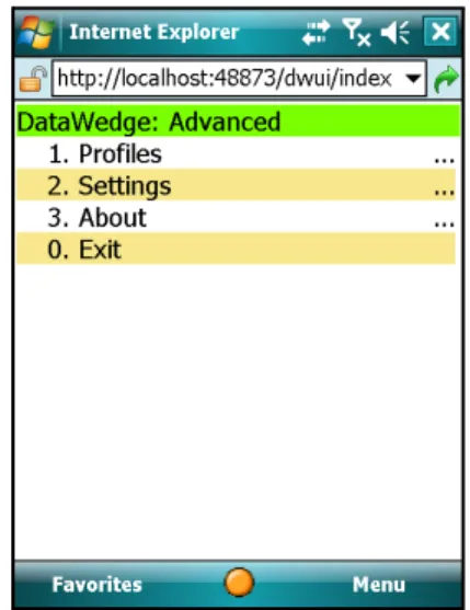
Advanced Configuration Main Menu
The advanced cnfiguration main menu is displayed on the mobile device screen. This page consists of four menu items, namely Profiles, Settings, About and Exit.
Figure 3-6 Advanced Configuration Main Menu Page
Use the appropriate keyboard shortcut or the touch screen to navigate through the main menu.
•
Select Profiles to open the Profiles menu.•
Select Settings to open the Settings menu.•
Select About to display product information of DataWedge.•
Select Exit to exit from DataWedge advanced configuration mode.Chapter 4 Configuring DataWedge Settings
This chapter provides information on how to set the general DataWedge configuration options. The configuration interface has built-in functionality to modify the general DataWedge settings.
Settings Menu
The Settings menu page is displayed when the Settings option is selected from the main menu. Use the Settings menu page to configure general DataWedge settings.
Figure 4-7 Settings Menu Page
•
Use Profile Selection to select whether profile switching should be automatic or manual (See Profile Selection for more details).•
Use Manual Profile to select which profile to use when Profile Selection is set to "Manual" (See Setting Manual Profile for more details).•
Select Log to configure logging options (See Configuring DataWedge Log Settings for more details).•
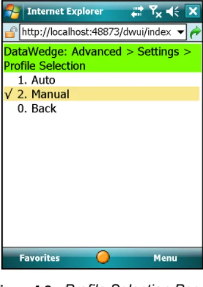
Select Back to return to the main menu. Whenever exiting from the Settings menu, a dialog box appears prompting for confirmation on whether or not to save the changes made to the settings. Press OK to save the changes made.Profile Selection
Use Profile Selection page to select whether profile switching should be automatic or manual. This setting enables/disables switching of profiles based on the foreground application on the mobile computer.
Figure 4-8 Profile Selection Page
Automatic Profile Selection
Auto profile selection enables switching between profiles based on the foreground application. To enable automatic profile selection, select Auto from the Profile Selection menu.
When automatic profile selection is enabled, DataWedge monitors the foreground application in the mobile device by checking the application name of the foreground application (exe name). When DataWedge detects a change in the application name, it searches for the profile associated with that application and loads that profile. If an associated profile cannot be found, Profile0 is used.
The profile must be enabled for DataWedge to load it. i.e. DataWedge only loads profiles that have their status set to "Enabled".
Manual Profile Selection
Manual profile selection is similar in functionality to the earlier versions of DataWedge. When profile selection is set to Manual, DataWedge does not switch between profiles automatically, based on the foreground application, and only uses the profile specified in the Manual Profile page.
To enable manual profile selection, select Manual from the Profile Selection menu. See Setting Manual Profilefor details on selecting a manual profile.
Configuring DataWedge Settings
4 - 3
Setting Manual Profile
Select the Manual Profile option from the Settings menu to move to Manual Profile page.
Figure 4-9 Manual Profile Selection Page
The manual profile selection page lists all of the available profiles. Select the desired profile name. Make sure that the profile selected is enabled (See Enabling/Disabling a Profile).
If the profile selection is set to manual and the selected profile is disabled, DataWedge cannot send data to the foreground application (See DataWedge Behaviors)
Manual Profile
The manual profile is the profile which is used by DataWedge when profile selection mode is set to "Manual". While in manual mode, DataWedge sends data only to the foreground application associated with the manual profile. By default, the manual profile is set to Profile0. This setting allows DataWedge to send data to any foreground application. A user-created profile can be set as the manual profile using the Manual Profile selection page.
DataWedge Behaviors
The table below explains the different behaviors of DataWedge according to the Manual Profile and Profile Selection settings.
In this example, Profile1 is a user created profile which has App1.exe set as its associated application. Apart from Profile1, the default profile, Profile0, is also available in DataWedge.
Table 4-1 DataWedge Behaviors
Profile Selection Setting Manual Profile Setting Profile0 State (Enabled /Disabled) User Created Profile (Profile1) State (Enabled /Disabled) Current Foreground Application DataWedge Behavior
Manual Profile0 Enabled Enabled or Disabled
Any application DataWedge runs with Profile0 (the default profile) configuration
Manual Profile0 Disabled Enabled or Disabled
Any application DataWedge is idle and does not send data to the foreground application Manual Profile1 Enabled or
Disabled
Enabled Any Application DataWedge runs with Profile1 configuration Manual Profile1 Enabled or
Disabled
Disabled Any Application DataWedge is idle and does not send data to the foreground application Auto Any profile Enabled or
Disabled
Enabled App1.exe DataWedge sends data to foreground application (App1.exe)
Auto Any profile Enabled or Disabled
Disabled App1.exe DataWedge is idle and does not send data to the foreground application. (App1.exe)
Auto Any profile Enabled Enabled or Disabled
Any application except App1.exe
DataWedge runs with Profile0 configuration Auto Any profile Disabled Enabled or
Disabled
Any application except App1.exe
DataWedge is idle and does not send data to the foreground application..
Configuring DataWedge Settings
4 - 5
Configuring DataWedge Log Settings
Log File Overview
DataWedge application has built-in logging capabilities to record errors, warnings, and other diagnostic messages. These messages are saved to a text file (DWLog.txt).
The log file records the log entries in the following format:
<Time Stamp>:<Message Type>:Message
<Time stamp> is formatted as YYYY/MM/DD hh:mm:ss.
<Message Type> depicts the type of message that is logged. The following message types can be logged. • Error - an error has occurred
• Warning - a warning is issued
• Message - DataWedge system messages, indicating it is performing a task etc.
• Data - data read from input devices and intermediate data modified by process plug-ins can be logged to the log file.
Sample Log File
$ 2009/09/09 02:49:32 Error Invalid Configuration XML
Select the Log option from Settings menu to access the Log page.
Figure 4-10 Log Menu Page
There are four configurable settings for the log file.
•
Select Log size to set the physical size of the log file.•
Select Backup folder to define a location to save the log file.•
Select Cache folder to define a location in which the temporary log file is written.Define DataWedge Log Size
To set the physical size of the log file, select the Log size option to move to the Log size page.
Figure 4-11 Log Size Page
Select the storage capacity to allocate for the log file. The maximum allowed size for the log file is 1 MB.
Define Log Backup Folder
The Backup folder specifies the location where DataWedge saves the log file upon exit or upon being stopped. Select Backup folder from the Log menu page to move to the Backup folder page.
Figure 4-12 Log Path Page
Using the mobile device keypad and/or the onscreen keyboard, enter the backup folder for the log file, and then press Save to save.
NOTE If the log file exceeds the set size, DataWedge backs up the text file (DWLog.bak) and creates a new log file (DWLog.txt) to save the new log entries. However, DataWedge creates only one back up file and the previously created backup file is replaced by the new back up file.
Configuring DataWedge Settings
4 - 7
DataWedge writes the log file to the folder specified upon exit or upon being stopped.
Define Cache Folder
The Cache folder specifies a location where the DataWedge log file is written to whilst DataWedge is running. Windows Mobile makes use of persistent (flash) storage for most of its folders. Writing to persistent (flash) storage can be slow, so DataWedge allows the use of non-persistent (RAM) storage to speed up the logging process. Select Cache folder from the Log menu page to move to the Cache folder page.
Figure 4-13 Log Temp Path Page
Use the mobile device keypad and/or the onscreen keyboard to enter the location for the temporary log file, and then press Save.
By default the cache folder is set to \Temp. For many Motorola devices this default setting is acceptable. An alternative for Windows Mobile devices is \Cache Disk.
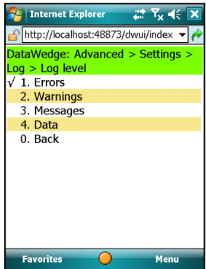
Define Log Level
Select the Log level option from the Log menu to move to the Log level page.
The Log level specifies the level of detail that is logged. Log events up to the given level are written to the log file.
Figure 4-14 Log Level Page
Use the menu to set the log level.
•
Select Errors to log only error messages.•
Select Warnings to log error and warning messages.•
Select Messages to log errors, warnings and messages.Chapter 5 Managing Profiles
This chapter describes how to add and remove profiles and also provides a screen-by-screen tutorial of how to associate applications to the profiles.
From the DataWedge main menu page, select Profiles to access the Profile menu.
Profiles Menu
The Profiles menu is displayed when Profiles is selected from the main menu.
Figure 5-15 Profiles Menu Page
The Profiles menu page lists all the profiles used in DataWedge. Use this menu to access each profile configuration.
•
Select Profile0 to move to configure Profile0 (the default profile).•
Select Add new to add a new profile.Creating a Profile
From the Profiles menu select the Add new option to create a new profile. DataWedge configuration moves to a profile name entry form and automatically suggests a unique profile name.
Figure 5-16 Profile Name Entry Form
Using either the device keypad or the onscreen keyboard, press Save to accept the suggested profile name, or enter a preferred name for the new profile and press Save.
When a new profile is created, DataWedge automatically assigns default settings to that profile. The new profile is added to the list of profiles. To configure the new profile select it from the profile list.
Profile Configuration Menu
Newly created profiles can be customized to suit user requirements.
Figure 5-17 User Defined Profile Menu Page
Managing Profiles
5 - 3
By default, the new profile is enabled upon its creation.
•
Select Enabled to enable/disable the profile•
Select Applications to associate an application to the profile.•
Select Input to configure an input plug-in for the profile.•
Select Output to configure an output plug-in for the profile.•
Select Routes to configure the routes for the profile.•
Select Rename to change the name of the profile.•
Select Delete to remove the profile.•
Select Back to exit the profile configuration. DataWedge prompts for confirmation to save the changes made to the profile. Select OK to save the changes made to the profile. Select Cancel to discard the changes made to the profile.Enabling/Disabling a Profile
To enable a profile, select Enabled from the profile configuration menu. When the profile is enabled, a tick (3) is displayed alongside Enabled. If Enabled is selected while the profile is enabled, DataWedge disables that profile.
Deleting a Profile
To delete a profile, select the Delete option from the profile menu. The system requires confirmation for removal of a profile. Select OK to delete the profile. Select Cancel to abort the operation.
Application Association
Several applications can be associated to a profile. DataWedge sends the output data to whichever of these applications is in foreground.
When profile selection is set to "Auto", DataWedge loads the profile associated with the current foreground application and sends data to it using the selected output plug-in. (See Setting Manual Profile for more details)
NOTE When exiting from the profile configuration menu, DataWedge saves the configuration information. Therefore, to save the changes made to a profile, select OK at the prompt when exiting from that profile.
Select the Applications option on the Profile menu to move to Applications page.
Figure 5-18 Application Association Page
The Applications page lists applications associated to the selected profile. Use this page to associate applications.
Adding Applications
Select the Add new option from the Applications page to move to the page where an application can be added to a profile.
Figure 5-19 Application Name Entry Form
Use the mobile device keypad or the onscreen keyboard to enter the name of the application in the field and press
Managing Profiles
5 - 5
Associated Application Menu
Select an application from the Applications menu to edit or remove that application.
Figure 5-20 Associated Application Menu
Use this menu page to edit/remove the associated application.
•
Select Edit to edit the application name. Using this option, it is possible to associate a different application (.exe) to the profile. The earlier set application is removed from the selected profile when a different name is saved.•
Select Delete to remove the application from the profile. At this point DataWedge configuration UI prompts the user for confirmation to delete the associated application from the profile. Select OK to confirm. SelectCancel to abort the deletion process.
Selecting a Data Route
Select Routes from the profile main menu to move to the page listing all available data routes.
Figure 5-21 Data Routing List
•
Select Add new to add a new data route to the selected profile. A form appears containing a automatically generated unique name for the new route. Press Save to accept the name or change the name as desired, then press Save to create the new route.As new routes are added, they are listed on this page. To configure a route, select the route from the list.
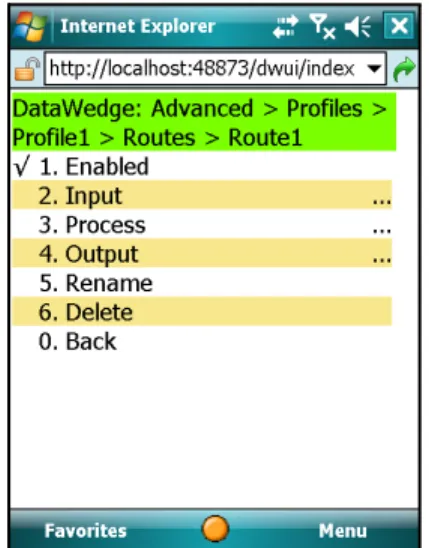
Data Route Configuration
Select a route from the data routes list to configure.
Figure 5-22 Data Route Configuration Main Menu
•
Select Enabled to Enable/disable the use of data route. When enabled, a tick (3) is displayed alongside Enabled. To disable, select Enable again to toggle the Enabled state.•
Select Input to move to a page where an input plug-in for the data route can be selected.•
Select Process to move to a page where the process plug-ins for the data route can be enabled and configured.•
Select Output to move to a page where an output plug-in for the data route can be selected.•
Select Rename to rename the data route.Managing Profiles
5 - 7
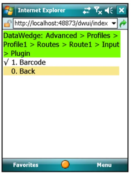
Define an Input Plug-in for the Data Route
Select Input from the route configuration menu to set an input plug-in to the data route.
Figure 5-23 Input Plug-in for Data Route
This page displayed the current input plug-in associated with the selected data route. Select Plugin to move to a page listing the available input plug-ins.
Figure 5-24 Input Plug-ins List
Select the desired input plug-in for the route from this page.
NOTE Input plug-in configuration is done at the profile level; no additional configuration is available at this level. See Configuring Input Plug-ins for details.
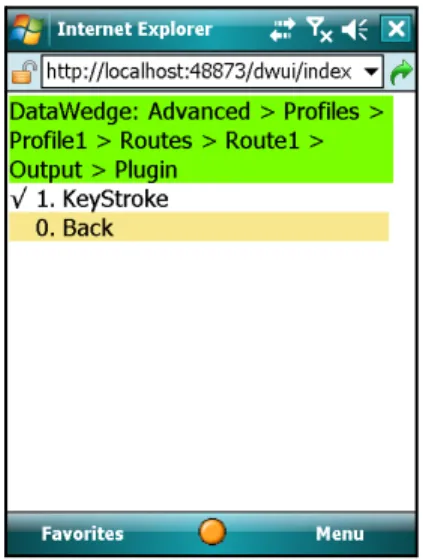
Define Output Plug-in for Data Route
Select the Output option from the route configuration menu to view the output plug-in associated with the selected data route.
Figure 5-25 Output Plug-in for Data Route
Select Plugin to move to the list of available output plug-ins.
Figure 5-26 Output Plug-ins List
Select the desired output plug-in for the data route from the list.
NOTE The output plug-in configuration is done at the profile level. Therefore no additional configuration is available at this level. See Configuring Output Plug-ins for details.
Managing Profiles
5 - 9
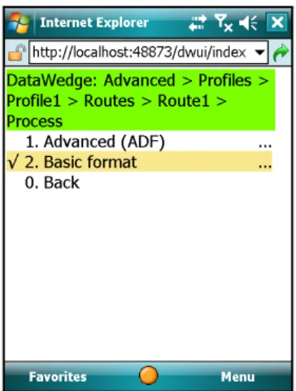
Defining Process Plug-ins for Data Route
Select Process from the route configuration menu to move to the page where available process plug-ins are listed.
Figure 5-27 Process Plug-ins Selection Page
•
Select Advanced (ADF) to enable and configure the Advanced Data Formatting (ADF) process plug-in for the data route.Chapter 6 Configuring Input Plug-ins
This chapter describes how to configure the input plug-in of a profile. DataWedge uses the input plug-in to access the selected input device (e.g. barcode scanner) and retrieve the data from it for processing.
Define Input Plug-in for Profile
Select Input from the profile menu to move to the Input plug-in selection page where all available input plug-ins are listed.
Figure 6-1 Input Plug-in Selection Page
Use the menu on this page for defining an input plug-in for the selected profile. DataWedge ships with one input plug-in which provides barcode scanning. As additional plug-ins are added, they appear in this list.
Select Barcode to start configuring the barcode input plug-in.
Barcode Scanner Plug-in
Configuring the Scanner Plug-in
When Barcode is selected, DataWedge configuration moves to the page where available scanners are listed.
Figure 6-2 Scanner Selection Page
Select a scanner from this list and move to the plug-in configuration page where all configurable options for that scanner are listed.
Figure 6-3 Scanner Plug-in Configuration Page
Following is a brief description of the menu items on the scanner plug-in configuration page.
•
Select Enabled to enable/disable the scanner.•
Select Decoders to access the supported decoders for the scanner.•
Select Reader Params to access the reader parameters for the scanner. (See Reader Parameters)•
Select Scan Params to access the scanner parameters for the scanner. (See Scanner Parameters)•
Select Interface Params to access the interface parameters for the scanners. (See Interface Parameters)Configuring Input Plug-ins
6 - 3
•
Select Auto trigger to enable/disable auto trigger mode for the scanner. When enabled, the scanner continuously reads barcodes. Use this feature for Motorola Micro Kiosks, such as the MK500. (SeeEnable/Disable Auto Trigger Mode)
Enabling/Disabling the Scanner
Select Enable to enable the scanner. When the scanner is enabled, a tick (3) is displayed alongside the Enabled
item. To disable, select Enable again to toggle the Enabled state.
Configuring Scanner Decoders
Before using the scanner to capture data ensure that the required symbologies are enabled. Select the Decoders
option from the scanner configuration menu to move to the page listing all decoders supported by the scanner.
Figure 6-4 Decoders List
This menu page lists all the decoders supported by the scanner. Use the More option to navigate through the list to configure additional decoders.
•
Select Enable All to enable all decoders for the selected barcode scanner.•
Select Disable All to disable all the decoders.NOTE Use of this feature on a battery powered mobile device is not recommended because it can cause the battery to discharge more rapidly.
Configuring Decoders
Select the decoder name from the list, to navigate to the page containing the configurable parameters for that particular decoder.
Example - Configuring EAN8 Decoder
Select EAN8 from the list to move to the EAN8 decoder configuration page.
Figure 6-5 EAN8 Decoder Page
The Enabled option changes the enable/disable status of the EAN8 decoder. When enabled the scanner allows reading of EAN8 barcodes.
Select Params to configure additional parameters of the EAN8 decoder.
Figure 6-6 EAN8 Params Page
Use the Convert to EAN13 option to enable/disable conversion of EAN8 barcodes to EAN13 barcodes. A tick (3) is displayed when this option is enabled.
Configuring Input Plug-ins
6 - 5
Configuring Reader Parameters
Select Reader Params from the scanner configuration menu to configure reader specific parameters.
Figure 6-7 Reader Parameters Page
Reader Parameters
The Reader Parameters settings differ depending on the barcode reader type. See Laser Scanner Reader Parameters and Imager Reader Parameters for details.
Laser Scanner Reader Parameters
Table 6-1 Laser Scanner Reader Parameters
Reader
Parameters Laser Values Description
Reader Type Laser Laser type scan engine is used. Aim type Trigger mode: On/off controlled by the trigger.
Trigger Hold mode: Trigger can be released but it remains active for the specified period of time.
Timed Release mode: Activation stops after a specified period of time, even if the trigger is held.
Aim duration 0 - 60,000 ms Sets the amount of time (0 - 60,000 ms in increments of 100 ms).
Aim mode Dot, Slab, Reticle, None Describes the aiming modes to use Dot – Projects a dot used for aiming Slab – Projects a line used for aiming
Reticle – Projects an aiming pattern used for framing a barcode.
None – set to none to disable this
Narrow beam Enable, Disable Sets the scan beam width to normal or narrow. Enable – Enable narrow beam
Disable – Disable narrow beam (enable normal beam) Raster mode Smart Creates a single scan line which opens vertically for
PDF417 symbols using the Smart Raster feature. This feature auto detects the type of bar code presented and adjusts its pattern accordingly. This provides optimal performance on 1D, PDF417, and EAN/UCC.
Cyclone A scan pattern which decodes 1D symbologies in any orientation.
None Raster mode disabled.
Open Always Opens the laser to a full sized raster pattern. Decodes 1D and PDF417.
NOTE Raster Mode is not supported on all devices.
Beam timer 0 - 60,000 ms Sets the maximum amount of time that the laser remains on (0 - 60,000 ms in increments of 100 ms). A value of 0 sets the laser to stay on.
Control scan LED Enable, Disable Not supported, do not modify default setting. Scan LED logic level Enable, Disable Not supported, do not modify default setting. Klasse Eins enable Enable, Disable Not supported, do not modify default setting.
Bidir. redundancy Enable, Disable Sets the read direction for the bar code redundancy. Bidirectional reads in both directions.
Configuring Input Plug-ins
6 - 7
Linear security level Linear Sec (Laser only)
Sets the number of times a bar code is re-read to confirm an accurate decode.
All twice: All twice: Two times read redundancy for all bar codes. All thrice: All thrice: Three times read redundancy for all bar codes. Long and Short: Long and Short:Two times read redundancy for long bar
codes, three times for short bar codes.
Redundancy + length: Redundancy + length: Two times read redundancy based on redundancy flags and code length.
Short or Codabar Short or Codabar: Two times read redundancy if short bar code or CODABAR.
Pointer timer 0 - 60,000 ms Sets the maximum amount of time that the pointer remains on (0 - 60,000 ms in increments of 100 ms). A value of 0 sets the pointer to stay on.
Raster height 0-100 in. Sets the Raster Height from 0 to 100 inches in increments of 5 in. Raster Height is not supported on all devices. DBP Mode Describes what type of Digital Bar Pulse (DBP) is being
produced by the scan engine.
Normal Normal – tells the engine to produce normal DBP. Composite Composite – tells the engine to produce composite DBP,
which is 2 different sets of DBP data multiplexed together for better decode performance.
Note: If the device does not support I2C or if using an older engine the default value for DBP Mode is Normal. An attempt to change this mode to Composite results in an E_SCN_NOTSUPPORTED error.
Table 6-1 Laser Scanner Reader Parameters
Reader
Imager Reader Parameters
Table 6-2 Imager Reader Parameters
Reader
Parameters Imager Values Description
Reader Type Imager Imager type engine is used. Aim type Trigger mode: On/off controlled by the trigger.
Timed hold mode: Trigger can be released but it remains active for the specified period of time.
Timed Release mode: Activation stops after a specified period of time, even if the trigger is held.
Presentation Special mode enables scanning when motion is detected in front of the imager. (Currently only supported by MK500)
Aim duration 0 - 60,000 ms Sets the amount of time (0 - 60,000 ms in increments of100 ms).
Aim mode Dot, Slab, Reticle, None Describes the aiming modes to use Dot – Projects a dot used for aiming Slab – Projects a line used for aiming
Reticle – Projects an aiming pattern used for framing a barcode.
None – set to none to disable this
NOTE Both Dot and Slab options are invalid for imager, thus if selected the setting is overridden to reticle mode.
Beam timer 0 - 60,000 ms Sets the maximum amount of time that the laser remains on (0 - 60,000 ms in increments of 100 ms). A value of 0 sets the laser to stay on.
Pointer timer 0 - 60,000 ms Sets the maximum amount of time that the Pointer Timer remains on (0 - 60,000 ms in increments of 100 ms). A value of 0 sets the Pointer Timer to stay on.
NOTE This parameter is not supported on all devices.
Img capt. timeout 0 - 60,000 ms Sets the maximum amount of time for the Image Capture Timeout (0 - 60,000 ms in increments of 100 ms). A value of 0 sets the Image Capture Timeout to stay on.
NOTE This parameter is not supported on all devices.
Img comp. timeout 0 - 60,000 ms Sets the maximum amount of time for the Image Compress Timeout (0 - 60,000 ms in increments of 100 ms).
NOTE Image Compress Timeout is not supported on all devices.
Configuring Input Plug-ins
6 - 9
Linear security Sets the number of times a bar code is read to confirm an accurate decode.
All twice: All twice: Two times read redundancy for all bar codes. All thrice: All thrice: Three times read redundancy for all bar codes. Long and Short: Long and Short: Two times read redundancy for long bar
codes, three times for short bar codes.
Short or Codabar Short or Codabar: Two times read redundancy if short bar code or CODABAR.
Focus mode Fixed, Auto Fixed mode is the only supported focus mode. Focus position Far, Near Specifies the Fixed setting, focus position for Far is 9
inches and focus position for Near is 5 inches.
Poor quality mode Enable, Disable This parameter allows poor quality 1D bar codes to be read, BUT adversely affecting the overall decoding performance.
Enable – Enables poor quality decoding for 1D barcodes. Disable – Disables poor quality decoding for 1D barcodes. Picklist mode Disabled, Enabled/HW reticule,
Software reticule
This parameter allows the imager to decode only the bar code that is directly under the cross-hair/reticule (+) part of the AIM pattern. This feature is most useful in applications where multiple bar codes may appear in the field of view during a decode session and only one of them is targeted for decode. When enabled, bPicklistMode overrides dwAimMode if no aiming is chosen and use the AIM_MODE_RETICLE mode. When enabled, bPicklistMode may adversely affect overall decoding performance.
Disabled – Disables picklist mode, so any bar code within the field of view can be decoded.
Enable/HW reticule – Enables picklist mode, so only the bar code under the cross-hair can be decoded.
Software reticule - Enables picklist mode, so only the bar code under the cross-hair can be decoded. In this mode the reticule is seen on the viewfinder as oppose to on the barcode surface. Especially used with Camera Scan.
Table 6-2 Imager Reader Parameters
Reader
DPM Mode Enable, Disable This parameter allows Direct Part Marking (DPM) bar codes to be read but may adversely affect overall decoding performance. DPM is a way of stamping bar codes directly on physical objects.
Support for this feature is available on DPM enabled mobile computers only. If this feature is not available and user attempts to enable it, an error
(E_SCN_NOTSUPPORTED) results.
Enable – Enables decoding of DPM bar codes. Disabled – Disables decoding of DPM bar codes.
NOTE This feature cannot be turned on in conjunction with Picklist as both these modes are mutually exclusive. An attempt to turn on both results in an error
(E_SCN_NOTSUPPORTED).
Illumination mode Auto, Always off, Always On Illumination modes to use. Possible values are:
Auto Illumination – In this mode the auto-exposure algorithms decides whether illumination is required or not. Always on – In this mode external illumination is always on.
Always off – In this mode external illumination is always off.
VF left pos. 0 – 600 This setting displays the top left X coordinate of the viewfinder window.
VF top pos. 0 – 800 This setting displays the top left Y coordinate of the viewfinder window.
VF right pos. 0 – 600 This setting displays the bottom right X coordinate of the viewfinder window.
VF bottom pos. 0 – 800 This setting displays the bottom right Y coordinate of the viewfinder window.
VF mode Disabled, Enabled,
Static reticule, Dynamic reticule
This setting displays the Viewfinder modes supported for scanning. Possible values are:
Disable - Viewfinder is not displayed during aiming and scanning.
Enabled - Only Viewfinder is enabled.
Static Reticule - Displays the Viewfinder as well as draws a red reticule in the center of the screen which helps tracking the barcode.
Dynamic Reticule - Displays the Viewfinder as well as draws a red reticule in the center of the image. If the barcode in the image is 'decodable' the reticule turns green to indicate this.
Table 6-2 Imager Reader Parameters
Reader
Configuring Input Plug-ins 6 - 11
Configuring Scan Parameters
Select Scan Params to configure the scan parameters.
Figure 6-8 Scanner Parameter Configuration Page
Use this menu to access and configure the scan parameters.
•
Select CodeID to specify the CodeID. VF feedback Disabled, Enabled,Reticule
This parameter allows selection of the different feedback parameters on a successful decode. Possible values are: Disabled - This mode disables any visual feedback on a successful decode.
Enabled - This mode displays the last image that
successfully decoded. The duration for which the image is displayed can be set by the Viewfinder feedback time. Reticule - This mode displays the last image that successfully decoded and also draws a reticule in the center of the image.
VF feedback time 0 - 60,000 ms This displays the Time for which the visual display selected by Viewfinder feedback mode.
For more information Please refer Motorola Enterprise Mobility Developer Kit for C Help.
Inverse 1d Mode Disabled, Enabled, Auto This parameter allows the user to select decoding on inverse 1D barcodes.
Disabled - Disables decoding of inverse 1D symbologies. Enabled - Enables decoding of only inverse 1D
symbologies.
Auto - Allows decoding of both positive as well as inverse 1D symbologies.
Table 6-2 Imager Reader Parameters
Reader