[
Technical Paper
]
In-Wheel Motor System
1. Introduction
Under the current circumstances in which more attention is being paid to environmental performance and problems concerning energy, the automobile industry, academic research institutes and a number of similar organizations are engaged in the
technological development of electric vehicles (EV) as a next-generation automobile candidate.
Two different drive systems are available for EVs. The first is the one-motor system in which a motor is installed in the body and the power is transmitted to both the left and right wheels via a differential device and a drive shaft. The other is the in-wheel motor (IWM) system in which motors are installed in the wheels.
Since the motors and reducers are installed directly in the wheels, an IWM system does not need a differential, drive shaft or other parts1–8)when compared
to a one-motor system. Free of the layout restrictions caused by these drive system components, the degree of freedom in vehicle design is increased greatly by an IWM system. In addition, with the removal of the differential and the drive shaft, energy loss is reduced and this allows for a reduction in electricity
consumption required when running, thereby allowing the driving range per charge to be increased.
Furthermore, this system is capable of not only controlling the driving force of individual wheels
independently but also of directly transmitting the driving force to the tire without the intervention of a drive shaft. This makes it possible to achieve highly-responsive control of the driving force. Making the most of this drive characteristic allows the vehicle driving performance to be improved significantly.
Noting that IWM systems provide driving systems suitable for next-generation EVs in this way, we have developed the NTN-IWM System that incorporates an IWM, which is composed of a reducer and a motor, and a control system linked with sensor-based information.
This paper reports the results of evaluation tests of the IWM reducer and motor sections, and of a road evaluation test done on an IWM-equipped vehicle.
2. Specifications and structure of the
developed product
2.1 Specifications
With a compact automobile with a displacement of 1500 cc in mind, we designed an IWM system assuming installation in the two rear wheels of such an automobile. We adopted a wheel size of 15 inches. The appearance and specifications of the IWM developed are shown in Fig. 1and Table 1.
**EV System Division Driveline System Engineering Dept.
**EV System Division Control System Engineering Dept.
With increasing global environmental concerns, much attention has been paid to electric vehicles for their high environmental performance. In-wheel motor drive systems for electric vehicles have the advantages of effectively maximizing interior space and providing vehicle driving performance due to the independent traction control ability of each wheel. NTNhas developed an in-wheel motor system with a sensor-based control system for the dawning electric vehicle age. This paper describes evaluations of its decelerator and motor. In addition, it reports on results of vehicle tests with the developed system.
Yuichi ITOH
*
Kayo SAKAI
*
2.2. Structure
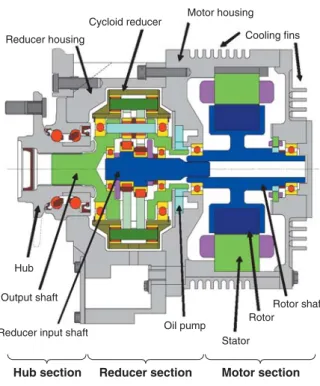
Fig. 2 is a cross-section of the IWM system, which has a structure that aligns the hub, reducer section and the motor section in a series configuration. Compared with other driving systems, an IWM system equipped with the driving section in the wheels has larger unsprung mass, putting it at a disadvantage in terms of vehicle stability and riding comfort. For this reason, reduced physical size and weight is an important challenge in developing an IWM system.
In an IWM system, the motor section accounts for a significant portion of its weight, and since the physical size of the motor is usually dependent on the
maximum torque it has to develop, reducing the required motor torque is effective in reducing the weight of the IWM system. During development reduction of the physical size and weight of the IWM system was achieved by adopting a reducer to reduce the torque required of the motor.
The lubrication system is based on an internal circulation scheme in which a built-in oil pump driven by the output shaft force-feeds the lubricating oil. The force-fed oil passes through an oil passage installed inside the motor housing and flows through an internal oil passage installed inside the rotor shaft and the reducer input shaft that rotates in conjunction with the rotor shaft and reaches the motor and interior of the reducer. This forced oil circulation not only lubricates the bearings and reducer but also cools the motor
stator (including the coil) and rotor. Furthermore, to help actively cool the stator and lubricating oil, the housing has cooling fins on its outer periphery and side faces so that the IWM is air-cooled.
Automatic transmission oil has been adopted as the lubricating oil to reduce the pipeline drag with the oil being pressure-fed by the built-in oil pump, and to reduce stirring loss due to rotating members in the rotor and reducer, as well as to ensure sufficient durability for the bearings and reducer.
In developing the IWM, we repeated a variety of durability tests such as water-submersion tests and vibration tests under severe conditions, which were identical to those under which NTNhub bearings are tested, to ensure sufficient reliability during actual running on roads.
2.2.1 Reducer section
A cycloid reducer equipped with a K-H-V-type planetary reducer mechanism9)has been adopted that
not only requires less space but also provides a high reduction ratio. To reduce loss within the reducer, roller bearings have been adopted in the internal gear that contacts the oscillating-rotating external gear and the output shaft.7), 8)
2.2.2 Motor section
Table 2shows the specifications of the motor. A concentrated winding system has been adopted to shorten the axial length. Using both magnetic field analysis and stress analysis, we derived the specifications for the shapes of the stator and rotor
Table 1Specifications of in-wheel motor
Maximum output 30 kW
Maximum torque 500 Nm
Cycloid reducer system 1/11
Radial gap type permanent magnet synchronous motor Air-cooled
Maximum rotational speed
1350 min-1
(equivalent to 150 km/h with a 0.6m tire diameter ) Reducer type
Reduction ratio Motor type Cooling system
Fig. 1Appearance of in-wheel motor
Fig. 2Cross-section of IWM
Reducer housing
Cycloid reducer Motor housing Cooling fins
Output shaft Hub
Reducer input shaft Oil pump Stator Rotor Rotor shaft Motor section Reducer section Hub section
running of the IWM, was taken as the reverse input condition.
3.1.2 Test results
Figs. 4and 5show the results of the measurement of the reducer transmission efficiency under the forward and backward input conditions. These charts show the efficiency of the reducer alone, with the power loss from the hub, the bearing of the input shaft, and oil seal in contact with the input shaft excluded. The horizontal and vertical axes denote, respectively, the rotational speed and the torque of the input shaft. The sign of the input shaft torque is positive for the forward direction input condition and negative for the reverse input condition.
The maximum efficiency was 98% under the forward input condition and 97.5% under the reverse input condition. With no noticeable difference observed in the transmission efficiency between the forward direction and the reverse direction, about the same efficiency was obtained for both power running and regenerative running.
3.2 Motor section
Table 5shows the test conditions for measuring the motor efficiency. To match the developed IWM, the motor section was configured so that a lubrication unit, which was installed externally, circulates the lubricant to supply it to the rotor and stator of the motor.
Fig. 6shows the results of the measurement of cores and for the layout of permanent magnets in
order to achieve a reduction in the power loss in the motor section to help realize an air cooled system as well as high speed rotary motion.
Table 3shows the specifications of the inverter. The inverter is provided with higher reliability through enhancements of a self-diagnostic function and circuit checking.
Cycloid reducer
Hub
Output shaft
Input shaft bearing Oil seal
Input shaft Input shaft to
the reducer
Fig. 3Cross-section of test reducer (including the hub)
Table 2Motor specifications
Motor type Radial gap type permanent magnet synchronous motor Winding system Concentrated winding
45 Nm 30 kW 15,000 min-1
Maximum torque Maximum output Maximum rotational speed
Table 3Inverter specifications
Drive power supply voltage DC 400 V Control power supply voltage DC 12 V
30 kW×2 10 kW×2 Sinusoidal wave PWM Output Carrier frequency Drive system Water-cooled Cooling system
Table 4Test conditions for reducer efficiency measurement
Maximum input shaft rotational speed 15,000 min-1
Maximum input shaft torque 45 Nm Automatic transmission oil
70˚C Lubricant
Lubricant supply temperature
Forced oil supply from the outside Lubrication system
3. Bench Test (Efficiency Measurement)
3.1 Reducer section
3.1.1 Sample and test conditions
Fig. 3shows the structure of the sample used in measuring the efficiency of the reducer and Table 4 shows the test conditions. The sample was composed of a reducer and a hub as principal components. The input shaft and the input shaft to the reducer were structured separately, with the power between them conveyed by means of a splined joint. Matching the developed IWM, the hub bearing was grease-lubricated and the reducer was oil-grease-lubricated. The oil lubrication system in the reducer section was configured so that a lubrication unit, which was installed externally, circulated the lubricant to supply it to the different parts of the reducer. The heater installed in the circulation path kept the temperature of the oil supplied at 70˚C.
The operating condition in which power was conveyed from the input shaft of the reducer to the output shaft, which simulates the power running of the IWM, was taken as the forward input condition. In contrast to this, the operating condition in which power was conveyed from the output shaft to the input shaft of the reducer, which simulates the regenerative
motor efficiency. The horizontal axis shows the rotational speed and the vertical axis is the motor torque. The maximum efficiency of the motor section was 94.7%.
Fig. 5Reducer transmission efficiency (for reverse input)
Fig. 6Motor efficiency
Motor rotating speed min-1
Effeciency % T orque Nm 0 0 10 20 30 40 50 100 97 94 91 88 85 82 79 76 73 70 2000 6000 10000 14000
Motor rotating speed min-1
Effeciency % T orque Nm 0 0 10 20 30 40 50 100 97 94 91 88 85 82 79 76 73 70 2000 6000 10000 14000
Fig. 4Reducer transmission efficiency (for forward input)
Motor rotating speed min-1
Effeciency % T orque Nm 0 -50 -40 -30 -20 -10 0 100 97 94 91 88 85 82 79 76 73 70 2000 6000 10000 14000
Table 5Test conditions for motor efficiency measurement
Maximum rotational speed 15,000 min-1
Maximum torque 45 Nm
Automatic transmission oil Forced lubrication from the outside Lubricant
Lubrication system
Table 6Test conditions for IWM efficiency measurement
Maximum rotational speed 1365 min-1
Maximum torque 500 Nm
Automatic transmission oil Built-in pump Lubricant
Lubrication system
3.3 IWM
3.3.1 Test conditions
An efficiency measurement test was conducted in the power running mode on the IWM system shown in Fig. 2, which consists of a hub, a reducer and a motor.
In the power running mode, load was provided by making the built-in motor act as the power source and allowing an externally installed motor to absorb the power generated. To measure the output torque, a torque meter was placed between the IWM and the power-absorbing motor.
Table 6shows the test conditions.
3.3.2 Test results
Fig. 7shows the results of the measurement of the efficiency of the IWM under power running conditions. The horizontal axis shows the wheel rotational speed and the vertical axis shows the output torque. Table 7 shows the specifications of an EV comparable to a typical 1500cc-class compact automobile, and Fig. 8 shows the vehicle driving power calculated on the basis of these specifications.
As shown in Fig. 7,the maximum efficiency of the developed IWM was 90%, with a maximum power output of 30 kW and a maximum torque of 500 Nm being achieved. In addition, a power output of 26 kW at a maximum rotational speed of 1365 min-1, which
corresponds to a vehicle speed of 154 km/h, was obtained. The results of calculations of driving power shown in Fig. 8demonstrate that this is equivalent to the power performance necessary to achieve a running speed of 150 km/h on a road with a zero-degree incline for a common 1500cc-class compact automobile propelled by two-wheel drive.
4. Test in Actual Car
4.1 Test vehicle
Fig. 9shows the appearance of the underbody of a vehicle equipped with the developed IWM. The vehicle is based on a commercially-available FF-vehicle, with the rear wheels equipped with the IWM. The
suspension type is based on a double wishbone system, with the auxiliaries being motorized and installed in the engine compartment with a battery dedicated to powering them.
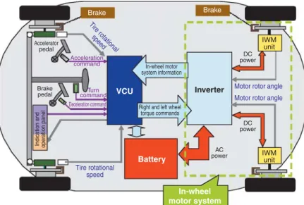
Fig. 10shows the structure of the vehicle control system.
The main constituent elements of the test vehicle are the IWM system, a vehicle control unit (VCU) and a lithium-ion battery. The VCU gives the inverter torque commands for the motors so that suitable driving power is generated in the right and the left IWMs independently in accordance with the driving conditions on the basis of information from the driver, including acceleration, deceleration and cornering commands. Following a torque command, the inverter converts DC power from the battery into the AC power required to drive the motor installed in the IWM.
Fig. 8Vehicle driving power of a 1500-cc compact class EV
Vehicle speed km/h Dr iving po w er kW 0 20 40 60 80 100 120 140 160 0 20 40 0 deg 2 deg 60 80 Gradient of roadsurface
Fig. 9IWM mounted in a vehicle (on the rear left wheel)
Fig. 7IWM efficiency
Wheel rotating speed min-1
Effeciency % T orque Nm 0 0 100 50 200 150 350 300 250 450 400 550 500 100 97 94 91 88 85 82 79 76 73 70 200 400 600 800 1000 1200 1400
Table 7Specifications of a typical 1500cc compact
vehicle class EV
Vehicle mass 1300 kg (including 110 kg for the weight of 2 passengers) Frontal projected area 2.6m2
0.32 0.015 Coefficient of drag
Rolling resistance coefficient
4.2 Temperature characteristics test
The temperature characteristics of an IWM while installed in a vehicle were assessed. The continuous rating characteristic, one of the important performance indexes of an IWM, is determined by the heat balance between the heating of the IWM itself and the external cooling action. In the assessment of the temperature characteristics of this IWM that is air-cooled, testing in an actual car is effective for reproducing the running wind. However, such a test poses difficulty in the securing of the battery capacity necessary for continuous running and stabilizing the running load. To solve this problem, we conducted tests using a chassis dynamometer on which a blast duct was installed as shown in Fig. 11. In accordance with the
speed of the rotation of the drum of the dynamometer, which corresponds to the vehicle speed, air simulating running wind was blown from the blast duct around the IWM.
With the aim of supplying electricity in a stable manner, an external power supply was used as the drive power supply for the IWM instead of the onboard battery.
In the test, the temperature of the motor coil section and that of the internal lubricant were measured under running conditions, with the vehicle speed and hill-climbing conditions used as parameters.
In this test, the allowable upper limit of the coil temperature was set at 180˚C from the viewpoint of the heat resistance of the coil insulation film. In addition, with the aim of preventing a reduction in the durability of the bearings and reducer parts used in the IWM, the allowable upper limit of the lubricant temperature was set at 120˚C.
As shown in Table 8, the test was conducted under the conditions of running resistance and a running
Fig. 11Vehicle test with chassis dynamometer
Blast duct
Running wind
Fig. 12Results of temperature characteristics test
Coil temperature Lubricant temperature 0 50 70 90 110 130 20 40 Time min T emper ature ˚C 60 80
Fig. 10Composition of vehicle control system
Brake IWM unit IWM unit DC power DC power
Indication and oper
ation panel
AC power
Motor rotor angle Motor rotor angle
Tire rotational speed Tire rotational speed Inverter Battery In-wheel motor system In-wheel motor system information
Right and left wheel torque commands Brake VCU Turn command Deceleration command Acceleration command Brake pedal Accelerator pedal
Table 8Conditions for the temperature characteristics test
Vehicle speed (Wheel rotational speed)
Equivalent to 70 km/h
(655 min-1)
Wind speed Equivalent to 70 km/h Equivalent to an incline of 2 degrees
25˚C Hill climbing resistance
Running air temperature
wind speed that correspond to a case where the vehicle is running at a speed of 70 km/h on a slope with a gradient of 2 degrees. Fig. 12shows the test results. Both the coil and the lubricant reached saturation temperatures that were below their
allowable upper temperatures. The lubricant exhibited a smaller difference between the allowable upper limit temperature and the saturation temperature reached. Considering that this temperature difference is about 10˚C, the assessment shows the possibility of
continuous running under the load conditions shown in Table 8if the outside air temperature is below 35˚C or so.
As shown in Fig. 8, the drive power for a car running at a speed of 70 km/h on a slope with a 2-degree gradient is nearly equal to the driving power for a car running at a speed of 100 km/h on a level road surface. If, for simplification of assessment, variation in the efficiency of the IWM due to variation in operating conditions is ignored, we may conclude that NTN's newly-developed IWM system is capable of cruising at 100 km/h on a level road surface (zero degrees gradient) because increased car velocity results in a greater forced convection cooling effect.
5. Conclusion
Assuming installation in the two rear wheels of a 1500cc-displacement compact automobile, we developed the NTN-IWM System in which a control system driven by sensor-generated information is incorporated into each IWM, which consists of a cycloid reducer and a motor.
The efficiency of each element of the IWM system was assessed. The highest efficiencies achieved were 98% in the forward direction and 97.5% in the reverse direction for the reducer section, 94.7% for the motor section, and 90% for the IWM. In addition, we obtained power equivalent to that which allows a common 1500cc-class compact automobile with two-wheel drive to run at a speed of 150 km/h on a road with no incline.
Furthermore, we conducted a temperature
characteristic test using a chassis dynamometer with the newly-developed IWM system onboard a vehicle, confirming that it is possible for the vehicle to run continuously at a speed of 100 km/h on a road with zero-degree incline in ambient air temperatures below 35˚C.
We are continuing road tests using a test vehicle with the objective of further improving reliability and commercializing our IWM system as early as possible.
Reference
1) Imayanagita, A. et al., "Development of In-wheel Motor System for Large-size Bus using 22.5-inch Wheel Mounted Motor," Toyo Denki Review, No. 113, pp. 9-14, 2006.
2) Tahara, Y. et al., Development of the In-Wheel Motor System, Transactions of the Society of Automotive Engineers of Japan, No. 131-06, 2006.
3) Okamoto, Y. et al., Development of High Efficiency In-wheel Motor System for using 20-inch Wheel Mounted Motor, Toyo Denki Review, No. 117, pp. 12-17, 2008. 4) Kaneko, Y. et al., Development of Compact and High
Power In-Wheel-Motor unit, Transactions of the Society of Automotive Engineers of Japan, No. 7-09, 2009.
5) Murata, S., Development of In-Wheel Motor Drive Unit, Transactions of the Society of Automotive Engineers of Japan, No. 28-10, 2010.
6) Akaho, D., Development of Vehicle Dynamics Control System for In-Wheel-Motor Vehicle, Transactions of the Society of Automotive Engineers of Japan, No. 120-10, 2010.
7) Suzuki, M. et al., NTN Technical Review, No. 73, pp. 56-59, 2005.
8) Suzuki, M. et al., NTN Technical Review, No. 75, pp. 46-52, 2007.
9) Morozumi, M., Theory and Design Calculation Method of Planetary Gears and Differential Gears, Nikkan Kogyo Shimbun Ltd., pp. 1-6, 1989. Yuich ITOH EV System Division Driveline System Engineering Dept. Kayo SAKAI EV System Division Driveline System Engineering Dept. Yusuke MAKINO EV System Division Control System Engineering Dept. Photo of authors