Model F822 thru F834 Mulsifyre
Directional Spray Nozzles, Open,
High Velocity
Page 1 of 6
FEBRUARY 2014
TFP810
IMPORTANT
Always refer to Technical Data Sheet TFP700 for the “INSTALLER WARNING” that provides cau-tions with respect to handling and installation of sprinkler sys-tems and components. Improp-er handling and installation can permanently damage a sprin-kler system or its components and cause the sprinkler to fail to operate in a fire situation or cause it to operate prematurely.
General
Description
The Mulsifyre Nozzles are open (non-automatic) nozzles and they are de-signed for use in water spray fixed systems for fire protection applica-tions where a high velocity water ap-plication may be required. There are two configurations: the basic Mul-sifyre Nozzle shown in Figure 1 and the Mulsifyre Nozzle with Model F880 Dust Cap shown in Figure 2. Each configuration is available in six differ-ent models that provide a wide range of orifice sizes and water distribution characteristics.
The Mulsifyre Nozzles are internal scroll type nozzles and they discharge a uniformly filled cone of relatively high velocity water droplets. Although the Mulsifyre Nozzles are designed primarily for use in fire extinguishment and control, they can also be used for exposure protection.
The Mulsifyre Nozzles are typically used in water spray fixed systems for the protection of special hazards such as:
• oil filled transformers and switching equipment,
• flammable liquid and gas storage tanks
• chemical process equipment, • conveyor systems,
• openings in fire walls, and
• other equipment that is defined as hazardous due to the possibility of a rapidly spreading fire.
Mulsifyre Nozzles with Model F880 Dust Caps are used in applications where protection is required against insect infestation or accumulation of debris within the nozzle. The Dust Cap is designed for both indoor and out-door use.
It is recommended that the end user be consulted with respect to the suit-ability of the materials of construction for any given corrosive environment. The effects of ambient temperature, concentration of chemicals, and gas/ chemical velocity, should be consid-ered, at a minimum, along with the corrosive nature to which the nozzles may be exposed.
The Model F822 thru F834 Mulsifyre Nozzles are a re-designation for the Gem Model F822 thru F834.
NOTICE
The Mulsifyre Nozzles described herein must be installed and maintained in compliance with this document, as well as with the applicable standards of the National Fire Protection Association, in addition to the standards of any other authorities having jurisdiction. Failure to do so may impair the performance of these devices.
The design of individual water spray fixed systems can vary considerably, depending on the characteristics and nature of the hazard, the basic purpose of the spraying system, the configuration of the hazard, and wind/draft conditions. Because of these variations as well as the wide range of available nozzle spray characteristics, the design of water spray fixed systems for fire protection must only be performed by experienced designers who thoroughly understand the limitations as well as capabilities of such systems.
The owner is responsible for maintaining their fire protection system and devices in proper operating condition. The installing contractor or sprinkler manufacturer should be contacted with any questions.
Technical
Data
Approvals
The Model F822 thru F836 Mulsifyre Nozzles are UL and ULC Listed, as well as FM Approved.
The Model F822 thru F836 Mulsifyre Nozzles with Model F880 Dust Caps are UL and ULC Listed.
Maximum Working Pressure 175 psi (12,1 bar).
Also refer to Figure 3, Note 2 Discharge Coefficient Refer to Figure 1 Water Distribution
Refer to Figure 3 - Part 1 of 2. Opti-mum flow pressure is 30 to 60 psi (2,1 to 4,1 bar).
Thread Connection 3/4 inch NPT
Physical Characteristics (Basic Nozzle)
Body . . . Brass Scroll . . . Brass Physical Characteristics
(Nozzle with Dust Cap)
Body . . . Chrome Plated Brass Scroll . . . Brass Dust Cap . . . EPDM Wire . . . Stainless Steel
Design
Criteria
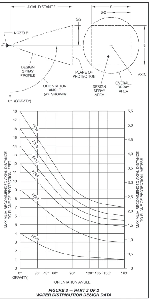
Nozzle PlacementWhere direct impingement of water spray onto all of the protected sur-face is required by the authority hav-ing jurisdiction, the nozzles are to be spaced and directed so that their spray patterns will completely cover the plane-of-protection with the mini-mum required average density. With reference to Figure 3 - Part 1 of 2, use of the “Design Spray Profile” for the “Design Spray Area” will help assure that direct impingement on all surfac-es will occur. The “Dsurfac-esign Spray Area” shown at the top Figure 3 - Part 2 of 2 on Page 4 consists of the square of length “S” within the circular “Overall Spray Area”.
The maximum recommended axial distances given in Figure 4 are based on maintaining the specified spray patterns under a maximum wind con-dition of 15 MPH (24 km/h).
Dust Caps
The Model F880 Dust Caps are rated for indoor and outdoor use over a temperature range of -60°F to 150°F (-51°C to 65°C). A minimum residual (flowing) pressure of 15 psi (1,0 bar) is required to assure release of the Dust Cap.
Main Pipeline Strainers
Main pipeline strainers per NFPA 15 are required for systems utilizing Mulsifyre Nozzles since their water-ways are less than 3/8 inch (9,5 mm) diameter. Individual strainers are not required since the openings in the scrolls will pass a 1/8 inch (3,2 mm) particle.
5" (125 mm) MIN. FREE LENGTH SCROLL
BODY
DUST CAP
RETAINING WIRE MODEL
NUMBER
F834 F832 F828 F826 F824 F822
1" DIA. (25,4 mm)
BODY 3/4" NPT SCROLL
(PASSES A 1/8" PARTICLE)
COLOR CODE PAINTED ON WRENCH FLATS 1-1/16"
(27 mm) ACROSS WRENCH FLATS
"L"
COLOR CODE YELLOW
ORANGE WHITE ALUMINUM
GRAY
ISO/SI LPM/bar1/2 NFPA
GPM/psi1/2
28,8
37,4
66,2 38,9
73,4 5.1
4.6 2.7 2.6 2.3 2.0
(70 mm)2-3/4" (42 mm) (42 mm) 1-5/8" 1-5/8"
(42 mm) (43 mm) 1-11/16" (47 mm) 1-13/16" 1-5/8" 33,1
K-FACTOR NOMINAL
LENGTH "L"
RED
FIGURE 2 MULSIFYRE NOZZLES
WITH DUST CAPS FIGURE 1
MODEL F822 THRU F834 MULSIFYRE NOZZLES NOMINAL DIMENSIONS
F828
F826
F824
F822
F834
F832
The shapes of the Design Spray Profiles remain essentially unchanged over the maximum recommended axial distance and the residual (flowing) pressure range of 30 to 60 psi (2,1 to 4,1 bar). Data applies to a residual (flowing) pressure range at the nozzle inlet of 30 to 60 psi (2,1 to 4,1 bar). (For pressures up to 175 psi (12,1 bar) consult Tyco Fire Protection Products Technical Services.) Data applies to a maximum wind condition of 15 MPH (24 km/h).
AXIAL DIST
ANCE FROM
NOZZLE, METERS
METRES
2,0 1,0
METRES
2,0 1,0
AXIAL DIST
ANCE FROM
NOZZLE, FEET
FEET 2
0 4 6
FEET
0 2 4 6
METRES
2,0 1,0
METRES
2,0 1,0
FEET
0 2 4 6
FEET
0 2 4 6
3. NOTES: 2. 1.
0 METRES
2,0 1,0
FEET 4
2 6 8
DATA KEY
0
OVERALL SPRAY PATTERN (RADIAL DISTANCE)
DESIGN SPRAY PROFILE (S/2)
METRES
2,0 1,0
FEET 4
2 6 8
AXIAL DIST
ANCE FROM
NOZZLE, METERS
AXIAL DIST
ANCE FROM
NOZZLE, FEET
AXIAL DIST
ANCE FROM
NOZZLE, METERS
AXIAL DIST
ANCE FROM
NOZZLE, FEET
AXIAL DIST
ANCE FROM
NOZZLE, METERS
AXIAL DIST
ANCE FROM
NOZZLE, FEET
AXIAL DIST
ANCE FROM
NOZZLE, METERS
AXIAL DIST
ANCE FROM
NOZZLE, FEET
AXIAL DIST
ANCE FROM
NOZZLE, METERS
AXIAL DIST
ANCE FROM
NOZZLE, FEET
2,0 6
4,0 3,0 2,0 1,0 0 1,0 0 3,0
4
16 12 10 8 6
5,0 4,0 3,0 2,0 2
0 4 2 0 12 10 8
4,0
1,0 0 3,0 2,0 1,0 1,0
0 1,0
2,0 0
8
4 2 0 6 4 2 0
0
6
16 18 14 12 10 8 4 2 0 14 8
12 10 6 4 0 2
14
FIGURE 3 — PART 1 OF 2 WATER DISTRIBUTION DESIGN DATA
Installation
Mulsifyre Nozzles must be installed in accordance with this section.
General Instructions
A leak tight 3/4 inch NPT nozzle joint should be obtained with a torque of 10 to 20 ft-lbs. (13,4 to 26,8 Nm). Higher levels of torque may distort the nozzle inlet and cause leakage or impairment of the nozzle.
Step 1. With pipe thread sealant ap-plied to the pipe threads, hand tighten the nozzle into the nozzle fitting. Step 2. Tighten the nozzle into the nozzle fitting using an adjustable cres-cent wrench. With reference to Fig-ure 1 apply the adjustable crescent wrench to the nozzle wrench flats. Replacement Dust Caps
When replacement Dust Caps are in-stalled, there is to be a minimum of 5 inches (125 mm) of Wire (Ref. Figure 2) between where the Wire is looped around the nozzle thread relief and at-tached to the Dust Cap. The minimum length of 5 inches (125 mm) will help to assure that there will be an unrestrict-ed flow from the nozzle outlet during operation.
Care and
Maintenance
The Mulsifyre Nozzles must be main-tained and serviced in accordance with this section.
Before closing a fire protection system main control valve for maintenance work on the fire protection system that it controls, permission to shut down the affected fire protection system must be obtained from the proper au-thorities and all personnel who may be affected by this action must be notified.
Mulsifyre Nozzles must never be painted, plated, coated or altered in any way after leaving the factory; oth-erwise, the spray performance may be impaired.
Care must be exercised to avoid dam-age to the nozzles before, during, and after installation. Nozzles damaged by dropping, striking, wrench twist/slip-page, or the like, must be replaced. Frequent visual inspections are rec-ommended to be initially performed for nozzles installed in potentially cor-rosive atmospheres to verify the integ-rity of the materials of construction as they may be affected by the corrosive conditions present for a given instal-lation. Thereafter, annual inspections per NFPA 25 are required.
AXIAL DISTANCE S
S/2 S/2
S
OVERALL SPRAY
AREA DESIGN
SPRAY AREA PLANE OF PROTECTION DESIGN
SPRAY PROFILE
ORIENTATION ANGLE (90° SHOWN) 0° (GRAVITY)
NOZZLE
AXIS
F826 F822 F824 F828
F832 F834
5,5
4,5
3,5
2,5
1,5
0,5
0 1,0 2,0 3,0 4,0 5,0 18
45°
MAXIMUM RECOMMENDED AXIAL DIST
ANCE
TO PLANE OF PROTECTION, FEET
30° 0°
(GRAVITY) 1 0 2 4 3 5 7 6 8 11 10 9 15
12 13 14 16 17
ORIENTATION ANGLE 120° 90°
60° 135°150° 180°
MAXIMUM RECOMMENDED AXIAL DIST
ANCE
TO PLANE OF PROTECTION, METERS
FIGURE 3 — PART 2 OF 2 WATER DISTRIBUTION DESIGN DATA
Water spray fixed systems for fire protection service require regularly scheduled care and maintenance by trained personnel. In addition to in-specting nozzles for proper spray per-formance during water flow trip tests of the system, it is recommended that nozzles be periodically inspected for broken or missing parts (including dust caps where applicable), load-ing/obstructions, or other evidence of impaired protection. The inspec-tions should be scheduled weekly or as frequently as may be necessary, and corrective action must be taken to ensure that the nozzles will perform as intended in the event of a fire.
For installations subject to freezing and where dust caps have been in-stalled, a periodic inspection must be performed for evidence of ice build-up from trapped condensate which could affect the proper release of the dust cap.
The owner is responsible for the in-spection, testing, and maintenance of their fire protection system and devic-es in compliance with this document, as well as with the applicable stan-dards of the National Fire Protection Association (e.g., NFPA 25), in addition to the standards of any other authori-ties having jurisdiction. The installing contractor or sprinkler manufacturer should be contacted relative to any questions.
It is recommended that water spray fixed systems be inspected, tested, and maintained by a qualified Inspec-tion Service in accordance with local requirements and/or national codes.
Ordering
Procedure
Contact your local distributor for avail-ability. When placing an order, indi-cate the full product name and P/N. Mulsifyre Nozzles
Specify: Model (number) Mulsifyre Nozzle, P/N (specify):
Model F822 . . . P/N 49-800-1-822 Model F824 . . . P/N 49-800-1-824 Model F826 . . . P/N 49-800-1-826 Model F828 . . . P/N 49-800-1-828 Model F832 . . . P/N 49-800-1-832 Model F834 . . . P/N 49-800-1-834 Mulsifyre Nozzles with Dust Caps Specify: Model (number) Mulsifyre Nozzle with Model F880 Dust Cap, P/N (specify):
Model F822 . . . P/N 49-801-1-822 Model F824 . . . P/N 49-801-1-824 Model F826 . . . P/N 49-801-1-826 Model F828 . . . P/N 49-801-1-828 Model F832 . . . P/N 49-801-1-832 Model F834 . . . P/N 49-801-1-834 Replacement Parts
Specify: Model F880 Dust Cap As-sembly, P/N 56-880-1-001
NOTE: The Model F880 Dust Cap may only be used for replacement on Mulsifyre Nozzles with chrome plated bodies. Otherwise failure for the Dust Cap to release may occur with resulting impairment of the system.
Specify: Blow-Off Cap Assembly for use with discontinued Model F822B thru F834B Mulsifyre Nozzles, P/N 56-802-1-001
NOTE: The Blow-Off Cap Assembly may only be used with the previously offered Model F822B thru F834B Mulsifyre Nozzles.
GLOBAL HEADQUARTERS | 1400 Pennbrook Parkway, Lansdale, PA 19446 | Telephone +1-215-362-0700