ME 114 – Engineering Drawing II
Dr. Oğuzhan Yılmaz
Associate Professor
Mechanical Engineering
University of Gaziantep
1
Purpose of Sectioning
On many occasions, the interior of an object is complicated or the component parts of a machine are drawn assembled.
The interior features are represented by hidden lines in usual orthographic views, which results in confusion and difficulty in understanding the drawing (Fig. 1a).
In order to show such features clearly, one or more views are drawn as if a portion had been cut away to reveal the interior (Fig. 1b).
This procedure is called sectioning and the view showing the cut away picture is called section view.
Definitions
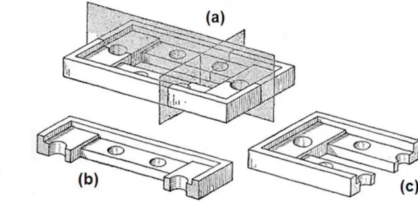
A section is an imaginary cut taken through an object to reveal the shape or interior construction. Fig. 2a shows the imaginary cutting plane in perspective view.
The imaginary cutting plane is projected on a standard view so that the sectional view with orthographic representation is obtained as shown in Fig. 2c.
A sectional view must show which portions of the object are solid material and
which are spaces. This is done by section lining (cross-hatching) the solid parts with uniformly spaced thin lines generally at 45º.
3
Cutting Planes
Various cutting planes can be selected for obtaining clear sectional views.
The plane may cut straight across (Fig. 3a) or be offset (changing direction forward and backward) to pass through features (Fig. 3b, 3c and 3d).
The plane may also be taken parallel to the frontal plane (Fig. 4a), parallel to the profile and/or horizontal plane (Fig. 4b and 4c), or at an angle.
Figure 3
Type of Sections
Depending on the number of cutting planes, sectional views can be simple with one cutting plane (Fig. 5) or complex with two or more cutting planes (Fig. 6). If the cutting plane-line cuts entirely across the object, it is called a full section. If the cutting plane cuts halfway through the object, it is a half section.
In addition to these, there are broken-out sections, rotated sections, removed sections, auxiliary sections, and assembly sections.
5
Full Section
When cutting plane passes fully through an object, it is called full section (Fig. 7).
Full Section with Offset Planes
The cutting plane may be offset in any portion in order to show some detail or to miss some part, as seen in Fig. 8.
Note that the change in plane direction is not shown on the sectional view (i.e. no edge is present on the object at this position since the cut is purely imaginary).
7
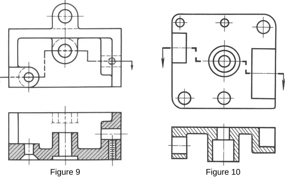
Full Section with Offset Planes
Fig. 9 and 10 are examples of full sections with offset cutting planes.
Half Section
Figure 11 A half section is made by cutting halfway through an object (Fig. 11). Thus, one half is drawn in section and the other half is an outside view.
9
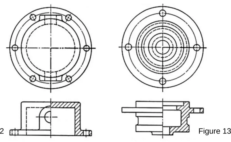
Half Section
In some cases, hidden detail on the unsectioned part may be shown for clarity or for dimensioning purposes (Fig. 12).
Half sections can be used to have advantage with symmetrical parts (Fig. 13) as well as with assemblies (Fig. 12).
Broken-Out Section
This type of section shows only an
interior portion of the object in section. Cutting plane passes partially through
the object. The area immediately in front of the plane is broken and
removed, which reveals interior details in this area.
At the point where the object is
considered broken, an irregular break line is used to indicate the break.
Fig. 14 and 15 illustrate the advantage of the broken-out section, which
eliminates the need for excessive section lining.
Figure 14
11
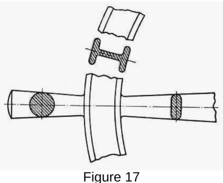
Rotated Section
Some parts of an object have to be rotated to show the section.
The cutting plane is passed perpendicular to the axis of the part to be cut.
The cut portion is revolved 90º and drawn in this position (i.e. turning the section until it is parallel with the plane of projection).
The resulting view is a rotated section.
Removed Section
This type of section is a revolved section drawn outside of the normal view.
They are used if there is restricted space for section or dimensioning prevents the use of an ordinary rotated section.
Several sections may be required when shape of the part is not uniform.
13
Removed Section
Figure 20
Assembly Sections
Assembly sections consist of a combination of parts.
The purpose of an assembly section is to reveal the interior of a machine or
structure so that the separate parts can be clearly shown and identified. However,
the separate parts do not need to be completely described.
Small amount of clearances between mating or moving parts on assembly drawing is not shown. Even the clearance between a bolt and its hole (which may be as much as 1 mm) is rarely shown.
On assembly drawing, only such hidden details (as needed for part identification or dimensioning) are drawn.
15
Hidden Edges and Surfaces in Section
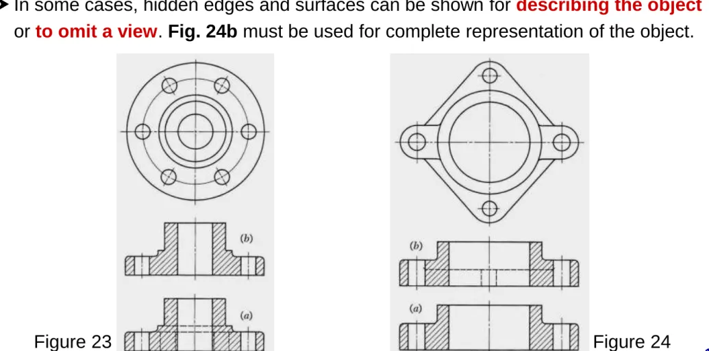
Sections are primarily used to replace hidden lines with visible lines. As a rule, hidden lines and surfaces should be omitted in sectional views.
Sectional view in Fig. 23a is incorrect. Because, hidden lines do not clarify the drawing. Thus, preferred sectional view should be as in Fig. 23b.
In some cases, hidden edges and surfaces can be shown for describing the object
or to omit a view. Fig. 24b must be used for complete representation of the object.
Visible Edges in Section
A section-lined area is always completely bounded by a visible outline, never by a hidden line or edge.
Therefore, all visible edges and contours behind the cutting plane must be shown in sectional view (Fig. 25b).
Otherwise, a section will appear to be made up of disconnected and unrelated parts (as in the case of Fig. 25a).
17
Section Lining (Cross-Hatching)
Section lining of a cut surface is indicated by fine lines, which are drawn as
continuous lines usually at an angle of 45º with uniform distance (about 2 mm). For smaller or larger areas, distance between lines can be from 1 mm to 4 mm.
Section lining or cross-hatching lines should not be parallel or perpendicular to any main visible line bounding the sectioned area.
Figure 27
Cross-Hatching of Adjacent Parts
Section lines on two adjacent pieces should slope at 45º in opposite directions. If a third or fourth piece adjoins the other pieces (as in Fig. 28), they ordinarily are cross-hatched at 30º and 60º.
An alternate use would be to vary the spacing without changing the angle.
19
Cutting Plane Lines
The cutting plane line is an imaginary plane
passing through an object at the place where a section is to be made.
This imaginary line is identified with reference letters along with arrows to show the direction in which the sectional view is taken.
The beginning and end styles of cutting plane lines are made bold. This is also done at the
portions where the cutting plane is offset (Fig. 29).
Thin Materials in Section
Very thin sections (such as sheet metal parts, gaskets or structural-steel shapes to small scale) may be shown in solid black with white spaces between the parts.
21
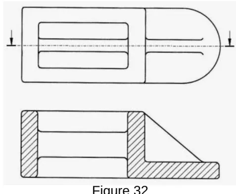
Ribs and Webs in Section
Ribs and webs are used to strengthen the parts. When the cutting plane passes through the ribs lengthwise, cross-hatching would give the misleading impression that the section was conical (Fig. 31b).
Therefore, cross-hatching is eliminated from the ribs and webs (as if the cutting plane was just in front of them) when the cutting plane passes longitudinally
through them (Fig. 31a and 32).
Ribs and Webs in Section
However, they are always cross-hatched if the cutting plane cuts them at right angles to their length or axis direction to show their thickness (Fig. 33).
23
Spokes and Arms in Section
When a cutting plane passes through pulley spokes or arms, cross-hatching is eliminated where the plane is thought of as being just in front of the spokes.
Even though the cutting plane passes through two of the spokes in Fig. 34, the sectional view in Fig. 34a must be made
without cross-hatching the spokes in order to avoid the appearance of a solid web as in Fig. 34b.
Lugs and Ears in Section
Small lugs or ears are treated like spokes and ribs.
Fig. 35a is an example in which the projecting lugs were not sectioned.
However, large lugs are considered as the solid base of the part, and hence they are sectioned (Fig. 35b).
25
Aligned Ribs, Spokes, Holes and Lugs
Ribs, spokes, holes and lugs are most common parts that may occur in odd numbers.
These parts will give an unsymmetrical and misleading section if the principles of true projection are strictly obeyed.
A combination of holes and ribs shown in one view is illustrated in Fig. 36.
The correct projection and section is shown at
Fig. 36c where rib and hole are drawn as if they were aligned (in other words, rib and hole are rotated to the path of vertical cutting plane and then projected to the top view).
Note that neither rib or hole was cross-hatched.
Aligned Ribs, Spokes, Holes and Lugs
When there are an odd number of spokes in a wheel (Fig. 37), they should be
shown aligned in the sectioned view so as to reveal their true location with reference to the rim and the axis of the wheel.
27
Aligned Ribs, Spokes, Holes and Lugs
Odd number of holes and lugs must also be treated likewise.
Fig. 38 and 39 show other examples of conventional representation. The sectional views are drawn as if hole and lug had been swung until the portion of the cutting plane passed through them and formed a continuous plane with the other portions.
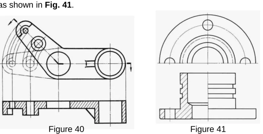
Aligned Elements in Full and Sectional Views
In full views, as well as in sectional views, certain violations of the rules of true projection are accepted as a good practice because they add to the clearness of the drawing. Fig. 40 may be shown straightened out or aligned in one view. This is to avoid drawing in a foreshortened position.
When the space available is limited to allow a satisfactory scale to be used for the
representation of a symmetrical piece, it is a good practice to make one view a half, as shown in Fig. 41.
29
Conventional Breaks
In order to shorten certain views of long parts, conventional breaks are recommended.
Parts considered as broken must have the same section throughout, or if tapered they must have a
uniform taper.
The breaks used on cylindrical shafts or tubes are often referred to as
“S-breaks” and are usually drawn entirely or partly freehand.