CALIFORNIA POLYTECHNIC STATE UNIVERSITY
Exploration Station KIDShake Table Design Report
Team Shake ‘n Break
Team Members:Jeremy Duhe [email protected] Phil Hopkins [email protected] Matt Ostiguy [email protected] Samantha Weiner [email protected]
1 Statement of Disclaimer
2
Thank you to everyone at the Exploration Station for giving us
3
Table of Contents
Table of Contents ... 3
List of Tables ... 5
List of Figures ... 5
Chapter 1: Introduction ... 7
Sponsor Background and Needs ... 7
Formal Problem Definition ... 7
Objective/Specification Development ... 8
Chapter 2: Background ... 9
Similar Existing Systems ... 9
The San Luis Obispo Children’s Museum ... 9
OMSI ... 11
Perot Museum of Nature and Science ... 11
The Randall Museum ... 12
Classroom Demonstrations ... 13
Chapter 3: Design Development ... 14
Initial Ideation/Brainstorming ... 14
Concept Designs ... 15
Concept #1 ... 19
Concept #2 ... 20
Visual Concept... 21
Considerations for Outdoor Use ... 22
Chapter 4: Description of Final Design ... 23
Overall Description/Layout ... 23
Detailed Design ... 23
Table Frame ... 23
Motion Plate Mechanism (Rail and Pillowblock) ... 24
Direct Crank ... 27
Rope and Spring Mechanism ... 28
Motion Plate and Building Blocks ... 31
Storage Moat ... 32
Mechanism Viewing Windows ... 33
4
Backboard ... 35
Aesthetics and Finishing Touches ... 36
Safety Considerations ... 38
Detailed Analysis ... 39
Analysis of Plate Motion Components ... 39
Analysis of Hand Crank System ... 39
Analysis of Rope and Spring System Components ... 44
Analysis of Table Frame ... 45
Analysis of Exterior Components ... 45
Cost Analysis ... 49
Chapter 5: Product Realization ... 52
Manufacturing Processes ... 52
Differences from Planned Design ... 56
Recommendations for Future Manufacturing ... 57
Chapter 6: Design Verification Plan ... 58
Component Testing ... 58
Magnet Spacing Testing ... 58
Spring Testing ... 58
Overall Table Testing... 60
Testing to Meet Objective Requirements ... 63
Chapter 7: Conclusions and Recommendations ... 66
References ... 67
Appendix A – Ideation Process and Decision Matrices ... 68
Appendix B – Drawing Packet ... 73
Appendix C – List of Vendors, Contact Information, and Pricing ... 111
Appendix D – Vendor supplied Component Specifications and Data Sheets ... 113
Appendix E – Detailed Supporting Analysis ... 122
5
List of Tables
Table 1. KIDShake Project Table Formal Engineering Requirements ... 8
Table 2. Spring factors of safety... 44
Table 3. Summary of FEA results for the one and two foot loading cases ... 49
Table 4. Current cost breakdown by assembly ... 50
Table 5. Results of spring testing for pull-rope mechanism ... 60
Table 6. Results of table verification testing ... 62
List of Figures
Figure 1. “Shake it Up” exhibit at the San Luis Obispo Children’s Museum ... 9Figure 2. “Shake it Up” building structure materials ... 10
Figure 3. “Shake it Up” exhibit table top ... 10
Figure 4. OMSI shake table exhibit ... 11
Figure 5. Shake table exhibit at Perot ... 11
Figure 6. Exhibit information of the effect of earthquake frequency and building height ... 12
Figure 7. “Living with a Restless Earth” exhibit at the Randall Museum ... 12
Figure 8. Rubber band shake table ... 13
Figure 9. Drill powered classroom shake table demonstration ... 13
Figure 10. Example of block design brainstorming session ... 14
Figure 11. Concept ideas after eliminating unfeasible options ... 15
Figure 12. Hand crank concept ... 15
Figure 13. Pull and release rope mechanism concept ... 16
Figure 14. Jumping mechanism concept ... 16
Figure 15. Hand pump mechanism concept ... 17
Figure 16. Block with pegs and magnets ... 17
Figure 17. Block with magnets ... 18
Figure 18. First concept of the KIDShake Table ... 19
Figure 19. Second visual concept design ... 20
Figure 20. Visual concept designs for overall table appearance and backboard logo ... 21
Figure 21. Render of table frame ... 24
Figure 22. Leveling feet from McMaster-Carr; A=2”, B=1.25”, C=3” ... 24
Figure 23. Initial custom pillow block and shaft plate motion design ... 25
Figure 24. Reworked guide rail from VXB ... 26
Figure 25. VXB 12mm CNC Bushing Linear Bearing Block ... 26
Figure 26. Assembly of pillow blocks, guide rails, and soft stops ... 27
Figure 27. Reid Supply 5.91 inch Diameter Dished Solid Hand Wheel with Revolving Handle ... 27
Figure 28. Hand wheel assembly in free space ... 28
Figure 29. Rope and spring mechanism ... 30
Figure 30: Spring mounting system ... 30
Figure 31: Harken Bull's Eye Fairlead ... 31
6
Figure 33. Side and top view of peg and magnet block ... 32
Figure 34. Example building block structure ... 32
Figure 35. Render of acrylic moat assembly ... 33
Figure 36: Mechanism viewing window ... 34
Figure 37: Render of table featuring backboard, siding, and doors ... 34
Figure 38. Backboard poster design as presented in Senior Project Expo ... 35
Figure 39: Discarded Visual Concepts for the Shake Table ... 36
Figure 40. The post Critical Design Review with approved color scheme and poster ... 37
Figure 41: Sample Challenge Card for Bridge Building ... 37
Figure 42. Crankshaft arm in Shaft/Crank assembly ... 40
Figure 43. FBD for Crankshaft Arm ... 40
Figure 44. Render of the connecting rod ... 40
Figure 45. Render of the connecting bracket ... 41
Figure 46. FBD of Connecting Bracket ... 41
Figure 47. Flanged bronze self-lubricating bearing ... 42
Figure 48. Section view showing flanged bronze bearing in relation to shaft and hand wheel ... 42
Figure 49. Example of 3/16’ diameter spring pin from McMaster-Carr ... 43
Figure 50. Hand wheel, shaft, and machine screw assembly ... 44
Figure 51. Example of loading case for the 140lb child standing atop the moat with two feet ... 46
Figure 52. Mises Stress of the 0.5 inch thick acrylic moat for the two foot loading case ... 47
Figure 53. Z-displacement of the 0.5 inch thick acrylic moat for the two foot loading case ... 47
Figure 54. Mises Stress of the 0.5 inch thick acrylic moat for the one foot loading case ... 48
Figure 55. Downward displacement of the 0.5 inch thick acrylic moat for the one foot loading case ... 48
Figure 56. Finished shake table frame ... 52
Figure 57. Table frame with bottom shelf, table mechanism shelves installed, and rail-guide system ... 53
Figure 58. Crank mechanism below moat ... 54
Figure 59. Shake table with hand crank mechanism assembled and functioning ... 54
Figure 60. Fully functioning shake table with both mechanisms complete. ... 55
Figure 61. KIDShake Table displayed at Mechanical Engineering Senior Project Expo ... 56
Figure 62. Springs tested for pull-rope mechanism ... 59
Figure 63. Soft stop for the pull rope mechanism ... 60
Figure 64. Three building heights used for testing ... 61
Figure 65. Hand crank testing displaying the relevance between the frequency of the hand crank, building block height, and time to fall. ... 62
7
Chapter 1: Introduction
Sponsor Background and Needs
The Exploration Station, located in Grover Beach, CA, is a non-profit children’s museum that educates young children of the Central Coast through science and technology. It hosts various science exhibits, interactive displays, and weekly activities in its main showroom. The showroom currently holds many exhibits where children can learn science and physical concepts through small interactive stations.
To contribute to their collection, the Exploration Station greatly desires a shake table exhibit that teaches children about earthquakes and their effects on the construction and destruction buildings. The exhibit consists of children building a structure out of building blocks and proceeding to test a structure they created by shaking the table at various speeds. They would like a hand-powered table that would be suitable to all children and adults but be designed for a target age of 10 years old. This table must safe for any user and be durable to withstand many years of use.
Formal Problem Definition
The Exploration Station of Grover Beach, CA has requested that we completely design and build a mechanical shake table exhibit to put in their children’s museum. This shake table must be completely mechanical and the user must input the desired motion of the shake plate. The target age for this exhibit is 10 years old, although it should be simple enough to be used by younger children and entertaining enough to lure in older learners. The team is not only fully responsible for the design of table but also the building blocks the user decides to knock down. The exhibit should display educational content and teach anyone using it about earthquakes and building structures. Specifically the table must demonstrate how differing building materials and building practices affect a structures ability to
withstand an earthquake. Our team should concentrate our focus on safety, functionality, reliability, and durability. The table should be designed to last multiple years and withstand the abuse of young
8
Objective/Specification Development
1. Table should not cause harm to the user, possess no pinch points, exposed mechanisms, sharp edges, etc.
2. Table shall simulate real earthquake characteristics and kids should learn something about earthquakes from this exhibit.
3. Entire cost of table shall be under $3000.
4. Max table footprint is 4 ft. x 4 ft., max shake plate size is 3 ft. x 3 ft.
5. Max table height shall be 32 inches, focus on ergonomics for 10 year old age group but table must be usable for older age groups as well.
6. Limit weight so that the table can be moved by two men and a furniture dolly.
7. Plate motion shall consist of two axes of motion activated by two different hand controlled mechanisms.
8. Table shall require minimal maintenance and should last 10 years.
9. Appearance must be visually attractive, use of colorful tones and construction theme is recommended.
10. Must design the table with as many commercially available parts as possible. 11. Building blocks should cater to various age groups.
12. Mechanical components shall be visible to the user. 13. Include a storage area within the table design.
Table 1. KIDShake Project Table Formal Engineering Requirements
Spec # Parameter Description Requirement or Target Tolerance Risk Compliance
1 Table Size 3’ x 3’ Max. H I, A, S
2 Exhibit Size 4’ x 4’ Max H I
3 Power “Kid” Power 1 child per axis H A, S, T
4 Height 30” Max H I
5 Weight 100 lbs. Max M T, A
6 Production Cost $3000 ± $1000 L A, S
7 User 10 yr olds ± 4 yrs M I
8 Noise 70 db ±10 db L I, T, A, S
9 Movability 2 People ± 1 Person M I, T
*H=high, M=medium, L=low
9
Chapter 2: Background
Similar Existing Systems
We performed much background research on existing educational shake tables used in science museums and classrooms across the country. In each demonstration, children are instructed to build a structure out of items such as Legos, building blocks, and Lincoln Logs and then attempt to break the structure with a back and forth motion. Many different designs are utilized to obtain the motion needed to simulate an earthquake. Some designs involve electric motors while others use simple springs and linkages. Most systems we found were only capable of one direction of motion.
The San Luis Obispo Children’s Museum
The San Luis Obispo Children’s Museum houses a hand powered wooden shake table. In this exhibit, children build a structure out of plastic pieces and PVC piping and place it on the top plate of the shake table. The children are then instructed to turn a single hand crank, which moves the plate back and forth and causes the structure to fall. We were not able to see the mechanism used to obtain this motion, but assume it was some sort of simple linkage attached to the crank.
We made several observations about the exhibit, including things we would like to incorporate and things we would like to improve. An overall layout of the station can be seen in Figure 1 below. The first thing to note is the station took up a lot of space in the museum. The work table was very large and we would like to utilize a smaller size. We also thought the partition was unnecessary and actually inhibits children from being able to fully see the effects of the structure under the back and forth motion.
10 The building pieces consisted of plastic plates, plastic cross braces, and PVC piping. These pieces are shown in Figure 2 below. We liked the idea of the cross braces and how they add an element of structural support. We would like to incorporate some sort of magnet or connector to achieve similar support which enables the kids to learn more about structures than just simply piling blocks. However, we did find that the kids had trouble knocking down their structures because they were too structurally sound. Therefore, we would like to maintain a balance between the two extremes.
Figure 2. “Shake it Up” building structure materials
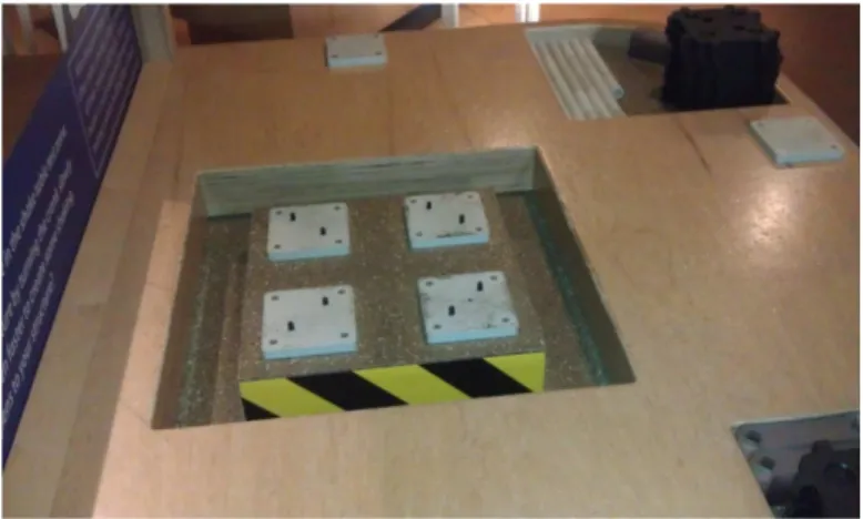
The table top of the shake table had many different features that we would like to consider incorporating into our design. The top plate is surrounded by space on all sides so it has ample space to move without pinching children’s fingers. Safety is a very big concern of ours and a “moat” design is a very good way of ensuring this. The plate also uses a rubber material that is used on playgrounds. We liked the idea of using such a material because it would provide a rougher surface for the building materials to rest on and is less noisy when pieces fall onto it. An overall view of the table top can be seen in Figure 3 below.
11 OMSI
The Oregon Museum of Science and Industry, OMSI, is a science museum in Portland, Oregon and creates and produces many exhibits for other organizations across the country. They currently have an electric shake table exhibit where kids can build structures out of wooden logs or building blocks with and without cross bracing and then test them. The table is actuated with a simple button that causes a motor to power the back and forth motion. We believe this shake table also is only capable of one direction of motion. A picture of the exhibit is shown below in Figure 4.
Figure 4. OMSI shake table exhibit
Perot Museum of Nature and Science
The Perot Museum of Nature and Science in Dallas, Texas hosts many informational displays and interactive activities including a shake table exhibit. The exhibit consists of two electric shake tables that are controlled by a touch screen computer. Children build structures out of plastic rods and connectors and test them on the moving platform. While the structures sit on the platform, the children control the amplitude and frequency that it shakes. One of the exhibits aims is to show children how smaller and larger buildings respond based on their natural frequencies. The computer also had options for the children to choose real past earthquake waveforms. This added to the appeal of the exhibit from children and adults.
12
Figure 6. Exhibit information of the effect of earthquake frequency and building height
The Randall Museum
The Randall Museum in San Francisco hosts an entire exhibit dedicated to earthquakes named “Living with a Restless Earth”. In one area kids can make their own earthquake by jumping on the floor which is connected to a seismometer that displays the intensity. In the basement is a second
seismometer which registers real earthquakes for guests to view. The museum also has three shake tables where children can build structures out of Legos and test their ability to withstand different strength earthquakes. We could not obtain pictures or information regarding the specific designs of the shake table stations. An overall layout of the whole exhibit can be seen below in Figure 7. Further research is being conducted on the “Living with a Restless Earth” exhibit.
13
Classroom Demonstrations
Another part of our background research consisted of looking at classroom shake table
demonstrations. These demonstrations tend to use very simple designs to acquire the desired back and forth motion. One simple design utilizes a wooden plate held in place by rubber bands attached to a wooden frame. This particular shake table allows motion in two directions; however, the user has little control over which way it moves. An example of this design is shown in Figure 8 below.
Figure 8. Rubber band shake table
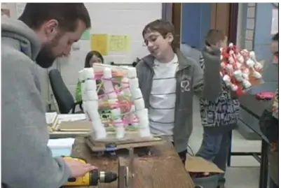
Many classrooms perform these shake table demonstrations with designs that use hand drills to power the back and forth motion. The drill drives a rotating disk that is attached to a linkage. This linkage is also attached to the plate, which causes the plate to move. Some of the setups utilize tracks for the plate to translate on and some use springs to keep the plate in place. An example of a drill powered shake table can be seen below in Figure 9.
14
Chapter 3: Design Development
The design development that was implemented to tackle this project has followed the generic “design process.” We defined the problem, completed our initial ideation, and decided on concept ideas. Because of the scope of this project, the initial ideation was done for lower level systems rather than the full system design. The subsystems consist of movement mechanisms, plate suspension, exterior structure, and block design. Each of these subsystems were tackled individually, and subjected to its own design process. We mentally evaluated and set aside many solutions for each of the
subsystems, then subjected the top ideas to decision matrices in order to select the final concept options.
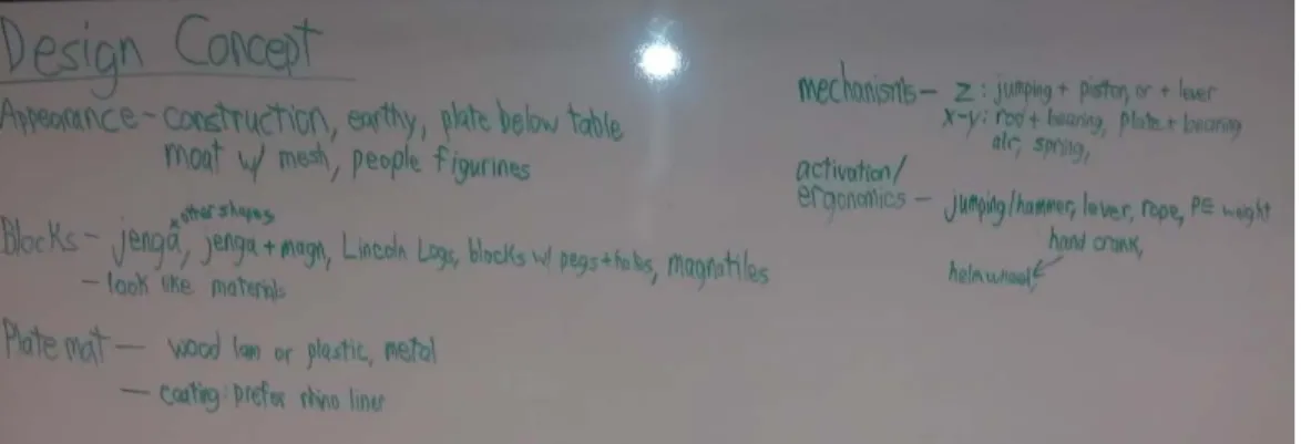
Initial Ideation/Brainstorming
The initial ideation and brainstorming was broken down into five different categories. These categories included overall appearance, block design, actuation mechanisms, activation mechanisms, and plate material. A separate brainstorming session on a whiteboard was conducted for each of these categories and every idea that could possibly be thought of was written down without question. Once everyone on the team went through each category a couple of times, we went back and we reviewed all of our ideas. To document the ideas we had, photographs of the whiteboard were taken at various stages. Figure 10 is provided as an example but all photos can be found in Appendix A. The ideas that were highly impractical, dangerous, or unfeasible were eliminated first. After this first round of elimination more ideas than necessary were still present. In order to reduce the number of ideas a second round of elimination occurred. During this elimination session, thorough discussion among the team was done in order to make sure there was enough reason for eliminating certain ideas and for retaining others. Figure 11 shows the ideas that remained after the brainstorming and elimination session was concluded.
15
Figure 11. Concept ideas after eliminating unfeasible options
In order to further finalize our design concept, decision matrices were implored. A decision matrix was created for actuation mechanisms, activation mechanism, types of building blocks, and plate material. With the matrix, various important aspects were considered and a point system determined which options would be best for our needs. All decision matrices can be found in Appendix A.
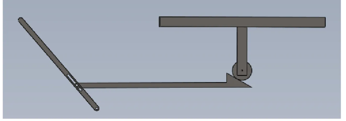
The activation mechanism is the user interface with the earthquake plate movement. The top three options per our decision matrix were the pull and release rope, hand crank, and pull and release lever. Upon further discussion however, it was decided by the Shake n’ Break team that the pull and release lever would not be utilized and it would be replaced with an alternative. The pull and release lever is very similar to the pull and release rope and having a much different activation mechanism would be beneficial to keeping the children’s interest. The up and down movement was then considered to be either a jumping mechanism (Figure 14) or a hand pump mechanism (Figure 15). The hand pump idea was thought of after the decision matrix hence why it is not included.
Concept Designs
16 The hand crank is a simple activation mechanism that will allow the shake table to move in the axial direction. The hand crank is very easy to use and will pose no safety concerns for the user. The frequency of the plate in the axial direction will depend upon how fast the hand crank is spun by the user. The faster the crank is spun, the higher the frequency of the earthquake.
Figure 13. Pull and release rope mechanism concept
The pull and release rope mechanism will move the plate in the transverse direction. The spring will be located inside the housing of the shake table and the rope will be located on the outside for the user to pull. The user will pull this rope as hard and fast as they can in order to move the plate in an attempt to destroy the structure they have built. Once the rope is pulled, the spring will be compressed and want to return the rope to its original position. Differing strength pulls and how often the rope is pulled will cause the transverse direction of motion to occur at many different frequencies. This mechanism also does not pose a great safety risk.
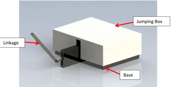
Figure 14. Jumping mechanism concept
Base Linkage
17 The jumping mechanism was decided upon as a concept idea because it would generate a lot of interest for the child user. The child would jump on the box mechanism shown in Figure 14 and this would in turn generate an up/down motion. Because this mechanism could pose a safety risk for the child, a bar would be attached to the outside of the table for the child to hold onto while jumping. The mechanism behind this up/down motion could pose some difficulty designing so it may not be the preferred method but a great concept idea nonetheless.
Figure 15. Hand pump mechanism concept
An alternative to the jumping mechanism for up/down motion is the hand pump mechanism. With the hand pump mechanism the user will push and pull on an accessible lever arm. This lever will be attached to another link which has a ramped cam on one end. As this cam link moves in and out, it will cause the table top to move up and down, providing the vertical motion desired. Constraining collars and shafts are not shown in Figure 15 but will be necessary for the mechanism to function properly. Note that all the activation mechanisms just presented, are concept ideas and not the final design.
The building blocks being made in conjunction with mechanical side of the shake table are just as important as the table itself. The motion of the table and the frequency at which it moves is strongly dependent upon on how the blocks are designed to fall. All of the possible ideas for the blocks were discussed during brainstorming and the best options were put in a decision matrix. Upon reviewing the decision matrix, it was decided that the shake table would benefit from having different blocks available instead of having just one. Our concept allows for the user to choose from three different blocks in order to build their structure. The three types include blocks with pegs and magnets, blocks with magnets only, and plain blocks. The nominal size of each block is 3/4” x 6” x 3/4”.
18
Figure 17. Block with magnets
19 Concept #1
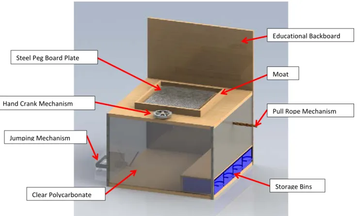
Figure 18. First concept of the KIDShake Table
In the above figure, our first overall shake table concept is presented. The only thing missing from this concept is the actual mechanisms within the table that cause motion in the plate. These mechanisms are still being designed and need to be integrated with our activation mechanisms. Changes decided upon but not yet corrected in our 3-D concept model are, the size of the polycarbonate sides and our third actuation mechanism. The polycarbonate sides are much larger than we will use in
actuality. We plan to only have enough polycarbonate for the users to view the mechanical mechanisms inside the table and the rest of table side will be another material. We decided upon this change
because large polycarbonate sheets are very expensive. The up/down actuation mechanism is the jumping actuation design presented in Figure 14. As explained earlier, this idea could cause pose possible safety hazards and would be difficult to design so we are shifting our focus to the hand pump mechanism as our up/down motion.
Pull Rope Mechanism
Jumping Mechanism
Storage Bins Steel Peg Board Plate
Hand Crank Mechanism
Clear Polycarbonate
Educational Backboard
20 Concept #2
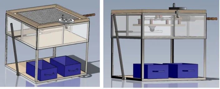
Figure 19. Second visual concept design
The second overall concept model fulfills many of our design specifications. The table has earthquake realism by having 3-axis of motion and each axis has its actuation mechanism. The
21 Visual Concept
Overall Table Visual
22 A proposed theme is to have the KIDShake table represent a construction site. This concept theme was chosen because our table emphasizes building construction practices and the effects of earthquakes. Also the construction color theme can be very appealing to children because of the bright colors and unique combination of colors. There are many possible ideas for this portion of the project but Figure 20 just emphasizes a few possible ideas that could be explored more. Ultimately the desire of the sponsor will have the most influence on the final look of the exhibit.
Considerations for Outdoor Use
Our sponsors initially had told us that the Shake Table was going to be used and stored outside most of the time. This gave us quite a challenge and a few solutions were found to partially solve the problem but not completely fix it. This prompted us to convince the sponsors to move the table inside. We had two major concerns, first, being in the sun will make the table top very hot and probably burn skin, two, Ultraviolet rays decimate almost any anti-corrosion coating we could possibly use. Ultraviolet damage reduced our material choice considerably since a plastic table top would warp and crack quickly, a wood top requires high surface finish maintenance, and composites would not endure it much better. This problem we thought could be solved fairly well just by covering the Shake Table exhibit with something opaque when not in use. The other option we thought of was buying a portable shelter (EZ-UP) or building a simple roof.
The first issue, solar heating, was an easily foreseen problem because metal was the only viable material, which gets rather hot in the sun. In order to confirm this and run parametric studies of our options, we created a simple heat transfer model in Microsoft Excel using transient lumped capacitance with solar radiation as the heat in and natural convection out. Since the table would heat up much faster than the air we used the hot plate facing up correlation (eqn 9.31) from Incropera &Dewitt Introduction to Heat Transfer (6th, 2011). We input data for dull and shiny (polished) 302 stainless steel, white
reflective coating over 302 stainless-steel, and both dull and shiny (anodized) 2024 Aluminum. We tested several parameters including plate thickness (1/8” to ¼”), daily temperature high (70 to 110 0F),
radiation absorptivity (.05 to .5), and the allowable table temperature. According to some quick research, skin burns fairly quickly at 140 0F and 120 0F is borderline safe for children. We found that no
matter what we did the table either reached or went well beyond the safe temperature of 120 0F. In the
23
Chapter 4: Description of Final Design
Overall Description/Layout
Our final table design allows a child user to move the shake plate in two different coordinate axes while attempting to knock down their structure. One axis shall be controlled by a hand crank wheel and linkage system which will allow the user to control the frequency of the shake plate by how fast they can crank the hand wheel. The second axis shall be operated by a free oscillation mechanism using two springs and a pull rope. The user will pull the rope to deflect the plate (and springs) from
equilibrium and once the rope is released the plate and springs will oscillate in a decaying under-damped 2nd order response. The plate is suspended on linear bearing guide rails which allow the two
mechanisms to operate simultaneously or on an individual basis. The space where the mechanisms are housed shall be surrounded by transparent acrylic siding so anyone can see the inner-workings of the table. There are three different types of building blocks available to build with and each block has a unique design to help simulate different building practices. The table has built in storage underneath the main workings and locking cabinet doors for excess building blocks and spare parts. A backboard is attached to the table which will provide some general information on earthquakes and the capabilities of the shake table, along with building challenges.
Since the concept stage of design a few major changes have been made. The largest change is the removal of one axis of motion. Our original design had the ability to move in three directions. Due to its complexity and questionable reliability of the designs, the vertical motion was eliminated. Our team and our sponsors believed this decision would allow us to focus on the reliability and durability of the remaining axes to withstand the constant use of young children. In addition to this, the overall table dimensions were also decided. The table footprint will be 40” x 40”, the moat height will be 32”, and the plate height will be 30”. Other less critical decisions included adding a base plate at the bottom of the table and locking cabinet doors for storage. Also, the overall color scheme will follow a construction theme, have red colored sides, and the backboard visual will allow even non-reading children to understand how to use the table.
Detailed Design
Table Frame
For the frame we chose to fabricate an angle iron weldment. This was decided because we could have relatively high precision, reduced bulk, and higher strength compared to a wood frame. It also makes the table much safer: better earthquake resistance, stronger base to mount the exterior to, and perfectly safe to climb on. It is largely composed of 1” x 1” x 1/8” angle iron, which gave the best compromise between strength, weight, machinability, and cost. There is much less load on the
24 all with weld-nuts on the opposing side since the frame thickness, 1/8” inch, is too thin to thread. For table leveling, a 5/16” stem adjustable rubber feet will be attached at the bottom. These soled table feet will reduce noise, wobbling, and strain on the frame.
Figure 21. Render of table frame
Figure 22. Leveling feet from McMaster-Carr; A=2”, B=1.25”, C=3”
Motion Plate Mechanism (Rail and Pillowblock)
25 capabilities, and smoothness of operation. During the design stage, we evaluated pre-made linear sliders verses a shaft and linear bearing system that we would purchase and modify to our needs. Ultimately the shaft and linear bearing system was chosen for several reasons. These reasons included the motion in the two horizontal axes would be attained simply, the plate motion would be purely mechanical, the system could be modified to our needs easily, and it was one of the cheaper systems. The premade linear sliders were not chosen because too much modification was required and almost all the premade sliders are built with or require DC servomotors for operation and our table is to be hand powered. By using our own shaft and bearing design we avoided all of the negatives of the premade system and the mechanism looks better overall. Our thought was to purchase the shafts, linear bearings, compression coil springs, and clamping shaft mounts while fabricating our own special two bearing, two axis pillow blocks out of aluminum (Figure 22). These components would be assembled into a two axis motion system with the coil springs resting on the shafts where indicated. Our estimate of total possible motion was about two inches before it ran into a hard stop (maximum spring deflection) while our motion goal was about one inch of deflection based on rudimentary testing.
Figure 23. Initial custom pillow block and shaft plate motion design
26
Figure 24. Reworked guide rail from VXB
Figure 25. VXB 12mm CNC Bushing Linear Bearing Block
27
Figure 26. Assembly of pillow blocks, guide rails, and soft stops
Direct Crank
The hand crank mechanism implemented in our design is most likely what comes to mind when one thinks of a hand-powered shake table. Since the beginning of the project, the hand crank had been in our design because of its simplicity, reliability and effectiveness to move the plate time and time again. This mechanism is the most intuitive way to let users provide variable speed motion input on the block buildings they wish to knock over. The crux of this design was finding pre-made, full-disk, hand-wheels that were both strong enough for the abuse and cheap enough to be considered. After much searching we found a polymer and metal hybrid hand-crank that we could modify slightly to rotate a shaft. Based upon this crank, we specified the remainder of linkage.
Figure 27. Reid Supply 5.91 inch Diameter Dished Solid Hand Wheel with Revolving Handle
VXB Pillow Block
Soft Stop
28 The hand-wheel is constructed of tough, reinforced plastic and its solid construction prevents injuries due to the hand getting caught in spokes. The overall diameter of the hand wheel is 5.91 inches and the handle height is 2.56 inches. Based on its build, this hand wheel can accommodate the hand size of many users. The shaft of the hand wheel attaches to a solid half inch steel shaft by a #10 machine screw through to the other side in addition to a #10 set screw to take up any play. This shaft rests on a SAE 841 Oilite flanged bronze sleeve bearing that provides alignment and resists the unwanted
moments on the shaft. On the end of this shaft is a 1.5 inch steel crank arm with a 5/16 bolt in it as the crank journal. The bolt connects the crank to a 5/16” heim joint and an all-thread rod. The opposite side of the all thread rod has a clevis pinned end and it is it attached to a custom-made bar which in turn attaches to the slider mechanism assembly. This bar is made of ¼” steel flat bar which has endurance strength nearly an order of magnitude larger than the greatest anticipated stress. This should ensure that it will never suffer fatigue failure.
Figure 28. Hand wheel assembly in free space
Rope and Spring Mechanism
The rope and spring mechanism has gone through several design iterations leading to our final design. We initially presented the idea of a mechanism consisting of a single compression spring with one end attached to the moving plate and the other end mounted at a fixed location. The rope would also be attached to the moving plate. The user would pull the rope and the plate would slide towards the user and compress the spring. This would provide the potential energy needed to allow the plate to freely oscillate once the user released the rope. We had some concerns about this design since the plate experiences a hard stop when the spring reached maximum compression. For this reason, we explored other design options that would eliminate such a collision.
29 To eliminate a hard stop of the table, we looked into a crank design incorporating a spring. This design consisted of two springs on either side of the plate and a cable that attached to both the moving plate and a hand crank. The cable would initially be slack and then be pulled in tension with the turn of the crank. This tension would displace one of the springs and upon release would push the plate back, displacing the other spring. This would result in cyclic back and forth motion and the table would oscillate freely until the plate came to rest due to frictional losses. Although this design eliminated the hard stops we were concerned about, there were some major drawbacks that we could not overlook. The intention of the mechanism is for the user to pull once and release to see the effects of free
vibration; however, a hand crank implies continuous rotation. Continuous rotation would not cause any damage, but it would defeat the purpose of the mechanism. We want to provide two different types of responses and a continuous rotation would essentially be the same as our crank linkage mechanism. This resulted in a rethinking of the purpose of the spring mechanism and we decided to revisit our initial design.
We really wanted to incorporate the freely oscillating spring mechanism into our shake table design but our original concern of the hard stops still loomed over the design. After reconsidering this problem, we reasoned that the mechanism would only experience one hard stop during the initial pull. Since the system loses energy due to friction, the table will not collide with the end of the rails after the first pull. We justify this single hard stop by utilizing bumpers at the end of the rails that can withstand such a force.
30
Figure 29. Rope and spring mechanism
Figure 30: Spring mounting system
31
Figure 31: Harken Bull's Eye Fairlead
Motion Plate and Building Blocks
The actual moving portion of the table is called the “plate”. During our brainstorming phase we decided on a composite of sheet metal backed with wood and this eventually led to the final design of a 21.5” x 21.5” square steel pegboard backed with 3/4 inch plywood. The pegboard was chosen so that we could easily show how the foundation of a building is placed into the ground. The pegboard plate works in conjunction with the pegged building blocks. Having blocks with pegs built into them allows the child user to fix certain blocks into the plate and this is how the foundation is simulated. We decided on making the pegboard an earthy brown color so it ties in with our construction oriented theme and foundation simulation idea.
Figure 32. Composite plate consisting of steel pegboard and wood. Left: Isometric Right: Bottom
To go with the pegboard we designed several types of blocks: plain, magnetic, and pegged with magnets. The blocks are all made of maple and cut to ¾” x ¾” x 6” nominal size then planed down a bit for aesthetic purposes and smoothness. The plain blocks were left their original wood color to indicate that these were buildings made with wooden frames. As these block structures are only held together by friction, they represent the weak structure. The magnetic blocks were made by drilling two sets of opposing holes 3/16” deep into the blocks 1” away from each end. In each hole a 1/8” x 1/4” disk-shaped neodymium magnet was epoxied at the bottom. The foundation blocks have two pegs four inches apart on one side to tie the structure to the ground and magnets on the other side to tie to the magnetic building blocks. These three styles of blocks will allow the children to understand the effect of building materials, construction, and use of a foundation on a building’s ability to withstand an
32
Figure 33. Side and top view of peg and magnet block
Figure 34. Example building block structure
Storage Moat
One of the sponsor’s desires was to have the shake table mechanics be visible by the user. To this end the sides of the shake table have clear windows so the user or other children can see the moving parts in action. A problem that arose with this however is that because the windows were small in terms of height due to the linear mechanism assembly being short, not much light would be
transmitted into the space below the plate. Without much light, the mechanism would hardly be seen and the sponsor’s goal would not be met. In order to remedy this problem a translucent material could be used for the moat. This would allow light to pass through the top of the table making the mechanism much more visible. The translucent plate will be constructed from acrylic but will not be completely clear. Instead the acrylic will be frosted for multiple reasons including: regular acrylic will scratch and wear over time and eventually become frosted anyway, abrasion resistant clear acrylic is prohibitively expensive, similar translucent materials such as glass are also extremely expensive) and would have to outsourced for fabrication.
33 size and shape with the center cutout and edge slots. It is sized a nominal 1/16” smaller than the inside of the frame which will provide a close fit that can easily be sanded down as needed. The moat bed will be secured at the edges by flat head machine screws through the wooden edges to under the topmost frame member. Slots instead of holes at the edges were chosen since the wall thickness would be too weak to hold if the moat bed deflected. Also, the center cutout has rounded corners to relieve the stress concentrations there.
Figure 35. Render of acrylic moat assembly
Between the moat and the motion plate we have as small a clearance as we could get away with: about 1/8”. With this design, even a child’s finger will have a difficult time getting under the shake plate. The moat edge is comprised of 2” x 2” birch with mitered corners and a slot along the full length of the bottom. The nominal length is slightly oversized to allow for minor fitting adjustments in the finished size of the frame weldment. The wood type was chosen to bring some natural qualities to the table and because it is an easily replaceable material. The slot along the bottom fits over the top edge of the frame and windows. This serves to protect the windows from fingers prying them away from the frame and possibly getting children’s fingers stuck in between. The bottom window edge is guarded by the thicker plywood siding immediately next to it.
Mechanism Viewing Windows
34
Figure 36: Mechanism viewing window
Siding and Doors
For the siding and doors we specified 1/2” ACX pine plywood since it offered the best combination of impact strength, stiffness, and decently lightweight. It also seemed to be the siding material preferred by our sponsors’ handyman that maintains all the exhibits. The siding measures 40” x 24” and has a set of three bolt holes, quarter inch, on each vertical side for mounting to the frame. The siding serves both as triangulation for the frame and is part of the exhibit’s aesthetic appeal.
35 Backboard
For ease of possible display redesign we made the backboard area above the table 30”x40” which fits several standard poster sizes with a 36” width. The backboard measures 40.25x60 inches and is made of 3/4” ACX pine plywood attached to the mounting holes made for the siding and windows. The poster on the backboard displays some information about earthquakes and the aspects we managed to model with the shake table. It also holds challenge cards for the more advanced users to apply their hand to. The poster design presented below is the one our team designed and presented at the Senior Project expo. Our sponsors wished to modify this design somewhat but were unable to finish their decision making before the printing deadline and so they decided to finish that aspect of the table themselves.
36 Aesthetics and Finishing Touches
We considered and rendered several versions of the table with different color schemes including blue and red, blue and brown, and cartoony versions with graphics on the sides. We wanted to avoid a childish looking exhibit which ruled out the first row pictures in Figure 40 below. We also wanted something that would stand out which the second row did not achieve.
Figure 39: Discarded Visual Concepts for the Shake Table
The design we decided on was a blue and silver theme using flat-faced gray doors and siding with aluminum edging. The silver colored aluminum accents the battleship gray siding and doors which keeps the bottom half from being boring but still clean and not detracting from the main focus of the table top. We still kept the black and yellow construction style border to tie in with the building theme of the table. This yellow and black banded theme we extended from the moat edges to around the backboard poster to keep a unified feel on the table-top.
37
Figure 40. The post Critical Design Review with approved color scheme and poster
The challenge cards were created in order to provide extra educational material in the way of guided discovery. We made the cards with 67 lb cardstock which was then laminated for a highly durable but cheap to produce design. There are nine challenges including: vary building height, varying frequency, bridge building, using foundations, wall building, cumulative damage, changing materials (blocks), non-square buildings, and the safe distance between buildings should one collapse. Pictures using the actual blocks are featured on every card in order to facilitate understanding of the challenge independent of reading level. Additionally, each card has a bit of trivia at the bottom that usually pertains to the challenge.
38 Safety Considerations
As with any machine that has human operators nearby or using it, safety guides many of our choices. Foremost in our safety concerns was eliminating the possibility of injuries during normal operation. The motion plate rides less than a 1/8” above the surface of the moat so that fingers cannot readily become stuck in between. The pull rope passes through a hole smaller than over 95% of
children’s fingers which we considered to be acceptable. The rope does present the possibility of minor rope burn but that heals quickly and is a lesson kids need to learn. The hand crank wheel was chosen to be solid (no spokes), since that could easily cause a great deal of pain with hands and limbs caught in it. Another worry was that the magnetic blocks might spontaneously connect themselves with enough force to hurt fingers. This was determined with actual testing of several different prototype blocks to find a good balance of safety and magnetic attraction. The windows were also a concern but this was addressed by hiding the upper edge in a slot, aluminum covers on the bolted ends, and a close fit to the plywood siding below.
Our second concern was whether the kids (and parents) could play with the table and not break it. To this end we decided to use a model of a 140 lb child moving at 10 mph running into the sides and windows. From this we confirmed that the ½” ACX siding and ¼” acrylic windows would be safe under all sorts of abuse. Also we modeled this child on top of the table to ensure the acrylic moat would not crack or break under load and again we found that using ½” acrylic was well within the material limits.
Another concern was edging the plywood siding, backboard, and cabinet doors to keep the plywood from splintering and to reinforce the most abused point of the exterior components.
39
Detailed Analysis
To ensure that many of the components of the KIDShake table can and will withstand the loading and use by multiple users, analysis was required. The analysis done has been broken down in five categories and multiple components within those categories were analyzed. The types of analyses that have been done include, statics, stress, buckling, fatigue, and finite element. For fatigue analysis the estimated worst case amount of cycles is 31 million. This value was calculated using the following criteria: 10 years at 52 weeks per year, 5 days per week, 1 hour per day, 200 rpm continuously for that hour. This cycle estimate gives a great over-estimation of the actual number of cycles the mechanisms will take. Pictures of our hand-written analysis and other analysis materials are located in Appendix E.
Analysis of Plate Motion Components
The manufacturer of the guide rail and linear bearing assembly (VXB) specified on its website that each pillow block could withstand a 115lb (510 N) dynamic load. This load represents an entire child weight on the mechanism and since our design has four pillow blocks, the rated load is well above a case that the table will actually experience.
Analysis of Hand Crank System
Crankshaft Arm Fatigue
40
Figure 42. Crankshaft arm in Shaft/Crank assembly
Connecting Rod Fatigue and Buckling
A concern of the 5/16” all-thread connecting rod was its buckling and fatigue failure. Treating the rod as an Euler column, we found that the critical load to cause buckling was 330lbs and since our expected load is 30lbs there is clearly no danger of buckling and very little out of plane deflection. For grade 2 all-thread, the most readily available, the fully corrected endurance strength was 17 ksi while the fluctuating load was positive and negative 0.76 ksi. This yielded a factor of safety of 22.4 which is very comforting. Both the tie rod end and clevis pin came with given load ratings well above the expected load, so we felt that crunching numbers for those parts would be superfluous.
Figure 44. Render of the connecting rod
41 Connecting Bracket Fatigue
Due to the connecting rod attaching to the connecting bracket approximately 1 inch below the top plane of the linear bearing blocks, torsional fatigue failure was a great concern. Assuming a 30lb input force, the torque acting on the bracket came to be 21.2 in-lbs. With steel as the material and a 1/8” x 1” cross section, the connecting bracket would see a stress of 4.38 ksi. For a ¼” x 1” cross-section the connecting bracket would see a 1.17 ksi stress. Fully corrected endurance strength for this situation is 9.2 ksi so both the 1/8” and ¼” thick bars are more than sufficient to resist failure. Ultimately, the ¼” thick bar was chosen since the deflection would be much less and ensure good response from the table.
Figure 45. Render of the connecting bracket
42 Bronze Bearings Stress, Friction, and Wear
We specified SAE 841 oil impregnated bronze bearings to hold the crank shaft in place with an expected maximum speed of 200 rpm. This gave a pressure-velocity rating of 700 psi*fpm, where the limit is 50,000 psi*fpm. The expected friction force under estimated normal conditions is about 1.3 lbs. Also, using the analysis framework found in Shigley’s Mechanical Design, the maximum bearing wear is 2.55 x 10⁻⁵ inches. The wear is considered negligible when compared to the worst case amount of use.
Figure 47. Flanged bronze self-lubricating bearing
43 Spring Pin Direct Shear Failure
A spring pin was initially specified in order to connect the hand wheel to the shaft that will ultimately cause one horizontal axis of motion for the plate. In the end we used a #10 machine screw which was close enough in size that we felt that doing the analysis over would be unnecessary. This spring pin shall be press fit into a hole through both the shaft and hand wheel. Using the maximum shear stress theory we calculated the maximum direct shear force the pin could experience. Two spring pin sizes were analyzed, a 3/32” diameter spring pin and a 3/16” diameter spring pin. An example of the spring pin cross section is displayed in Figure 35. For simplistic purposes the cross section of the pin was assumed to be a hollow shaft. The cross-sectional area used for calculation is slightly larger than in reality but this difference is negligible since the slot is very small.
Figure 49. Example of 3/16’ diameter spring pin from McMaster-Carr
44
Figure 50. Hand wheel, shaft, and machine screw assembly
Analysis of Rope and Spring System Components
A lawnmower starter pull cord was chosen for the rope mechanism because it is a thin rope with a handle attached that is already designed and rated for repeated yanking. The pulley is rated for far more load and cycles than the system will ever see in the planned ten year life. The polypropylene rope guide block is under very little load and it is unlikely that the rope will be pulled consistently enough to wear any type of groove. After selecting the rope type, an analysis of the springs that provide oscillatory motion was performed. The extension springs were selected based on two main parameters: the spring stiffness and the natural frequency corresponding to the stiffness. We set a maximum required force to compress the spring at 15 lb. Using Hooke’s Law, this equated to a spring stiffness of 30 lb/in for our desired 0.5 inch displacement. We initially selected springs with about the same spring stiffness but found that the calculated natural frequencies for springs in this range were much too high, about 4 Hz. In order to reduce this natural frequency to a more reasonable value, we looked at springs with a much lower stiffness. Our finalized springs have stiffness should be around 7-9lb/in and a natural frequency of 0.93 Hz. This is a much more reasonable natural frequency and we will not encounter any issues where children are not strong enough to move the table.
Table 2. Spring factors of safety
Parameter Factor of Safety
Service Load 3.21
End Hook Bending 2.58
Coil Yielding 5.07
Body Coil Fatigue 5.23
End Hook Bending Fatigue 4.16 End Hook Torsional Fatigue 5.23 #10 Machine
45 Based on the spring properties and our desired table response, a program in EES was written to calculate various factors of safety to ensure the spring can withstand the subjected loads. This program utilized equations from Shigley’s and is shown in Appendix E. The program calculates the stresses due to service loading, end hook bending; coil yielding and various fatigue possibilities. Factors of safety for each of these situations were calculated based on the stresses the springs can withstand compared to what they will actually encounter. All factors of safety were well within an adequate range and are shown in Table 3 below.
Analysis of Table Frame
Column Buckling
The main structural component of the frame consists of four 1” x 1” x 0.125” pieces of angle iron. One concern was how large of a load the angle iron could withstand before experiencing buckling failure. For the analysis, one piece was treated as an Euler column with fixed-fixed end conditions and no support from the table walls. Under these conditions the critical load for one column was 9377.5 pounds, which is far more than the table will ever experience. In the interest of saving weight and money, an analysis of wood 1” x 1” frame supports was performed using the same condition
assumptions. This analysis ultimately led to a critical buckling load of 1612.53 pounds, which is a decent load carrying capability, but after looking more closely at the loading conditions caused by the plate’s oscillatory motion the wood columns were eliminated for potential fatigue concerns and the angle iron frame was selected.
Threads for Mounting
We hoped that we could save a fair amount of work and possible errors by simply making ¼-20 threads in the 1/8” thick material the frame is made of instead of welding on forty something nuts. Unfortunately we calculated that the minimum length of threads was 0.139 inches by machinist handbook standards and so we must use weld-nuts.
Analysis of Exterior Components
Finite Element Analysis on Moat Bed
46 To analyze the stress of the moat it was decided that a finite element analysis (FEA) technique would be used because a hand calculation process could not be found. An FEA technique utilizes a displacement field assumption to determine the deformation of a part and then use that deformation to calculate stress. The problem parameters were determined and then a program called ABACUS was used to run the analysis. The moat was created in ABACUS using a shell element and the dimensions of the moat are 39.625” x 39.625” for the outside square and the inner cutout is 19.625” x 19.625”. The total surface area of the moat is 1185 in2 and the thickness used for analysis was 0.5”. The material used was
acrylic and this was modeled by inputting a Modulus of Elasticity (E) of 400 ksi and a Poisson’s ratio (ν) of 0.4. The boundary condition of the moat consisted of fixing the moat in the x-y plane which is the top face of the moat. The moat was fixed in this direction because it will not be able to move in those directions when in the table itself. The last boundary condition was fixing all 4 sides of the moat in the z-direction. When the moat is placed in the table angle iron along with wood siding will fix the edges of the moat. The inner parts of the moat are still free to displace in the z-direction however, thus they were not fixed in the model. The last part of the model was to add a load. To ensure the moat could withstand the weight of a child, a conservative loading case was used. A 140 pound child standing on both one foot and two feet were analyzed. This load was applied to the plate using a pressure. We model the area of 10 year old foot as a 9.75” x 3.5” rectangle and applied a 2lb/in2 pressure over that
area on each side of the moat. This in turn yields a 70lb load on the foot area for each side to model the case of a child standing on two feet. To model the one foot case, a 140lb load was distributed over just one foot area.
Figure 51. Example of loading case for the 140lb child standing atop the moat with two feet
Before running the analysis, the moat had to be broken up into many different elements in order to get an accurate result. This process is called meshing and the mesh size used for this analysis was a 0.5 in. The results of the FEA analysis were extremely promising. The ultimate stress of the acrylic is approximately 10,500 psi and the yield stress is approximately 8500 psi. The maximum stress and deflection came from one foot loading case. The 140lb child standing on foot caused a max stress of 1319 psi and a maximum displacement of 0.540 inches. This result is very acceptable in terms of how close the material is to both yield and failure. Because these results were acceptable, thicker material was not analyzed. In Figures 38 thru Figure 41, visualizations of the stress and displacement
47
Figure 52. Mises Stress of the 0.5 inch thick acrylic moat for the two foot loading case
48
Figure 54. Mises Stress of the 0.5 inch thick acrylic moat for the one foot loading case
49
Table 3. Summary of FEA results for the one and two foot loading cases
Loading Case Stress (psi) Displacement (in)
Two Foot 704 0.392
One Foot 1319 0.540
Backboard
For the backboard we wanted to make sure that if someone was hanging on it the plywood would not break or significantly deflect. As such we calculated that the stress applied to the plywood from the bolts with enough force to lift the table off of its front feet. In this case the static yield stress using ½” ACX pine was so far above the applied stress that we are not worried about it at all. Also the corresponding deflection was less than an inch which we felt was reasonable. We ended up using ¾” ACX because the cost was not that much more.
Cost Analysis
Per the specification, the entire cost of this project was to be under $3000. This specification has been met and our overall total cost is well below this figure. The entire cost of the project is estimated to be $1700. This cost includes all part costs, all shipping cost, and anything thing directly related or necessary to complete this project. Any items that were purchased fully belong to the Exploration Station of Grover Beach and any excess materials, unused parts, or spare parts will be included with the table delivery. Over the course of this project we tried to employ as many cost saving strategies as possible and we did our best to avoid unnecessary purchases. Our efforts paid off by not coming close to our budget cap. If another table were to be constructed, its estimated cost would be lower than the project cost the first time around. This was quite a learning process and money was spent on equipment or parts that ended up not being used. Excess material was purchased in many cases incase mistakes were made during manufacturing. If this table were to be professionally
50
Table 4. Current cost breakdown by assembly
ASSEMBLY ITEM QTY Cost Each Total Cost Supplier ROPE SPRING STARTER PULL CORD 2 $6.00 $12.00 Mcmaster, Ace
Eye bolt 1 $3.00 $3.00 Ace Hardware
fender washers 4 $0.20 $0.80 Ace Hardware
#8-32 machine screws 2 $0.25 $0.50 Ace Hardware 1.25" steel flatbar 1 $12.00 $12.00 Ace Hardware
3/8" fairlead 1 $4.00 $4.00 Online
springs 4 $2.00 $8.00 McMaster-Carr
Plastic Ball handle 1 $2.00 $2.00 Online
1/4-20x1.25 bolts 6 $0.30 $1.80 Online
PLATE 1/40-20 T NUTS 8 $1.00 $8.00 Ace Hardware
1/4-20X2 8 $0.50 $4.00 Ace Hardware
BROWN SPRAY PAINT 1 $5.00 $5.00 Ace Hardware 3/4" ACX HALF SHEET 1 $25.00 $25.00 Ace Hardware
pegboard 2 $35.00 $70.00 Diamond Life Gear
RAIL SLIDE 4-.7X15 ROUND HEAD 16 $0.40 $6.40 Ace Hardware
4-.7X45 FLAT HEAD 16 $0.60 $9.60 Ace Hardware 8-32X1/2 PANCAKE HEAD 8 $0.30 $2.40 Ace Hardware RUBBER WASHERS #8X1 8 $1.00 $8.00 Ace Hardware #8x1 PANCAKE WASHER 8 $0.40 $3.20 Ace Hardware 1X4 BIRCH per foot 8 $2.00 $16.00 Ace Hardware
12 mm rails 1 $90.00 $90.00 VXB
12 mm pillow blocks 9 $10.00 $90.00 VXB
FRAME 1X1X1/8 ANGLE IRON ft 48 $2.50 $120.00 McCarthy Steel 1/2X1/2X1/8 ANGLE IRON 16 $1.75 $28.00 McCarthy Steel 3/8" TABLE FEET 4 $10.00 $40.00 McMaster-Carr
1/4-20 FLANGE NUTS 52 $8.00 $8.00 McMaster-Carr
SIDING STEEL DOOR HINGES 4 $4.00 $16.00 Ace Hardware
Hasp lock 1 $10.00 $10.00 Ace Hardware
1/4-20x.625 ROUND HEAD 52 $0.30 $15.60 McMaster-Carr/ Ace 3/8" ACX FULL SHEET 1 $30.00 $30.00 Ace Hardware
black/yellow paint 2 $12.00 $24.00 Ace Hardware front doors 3/4" ACX 2 $10.00 $20.00 Ace Hardware Al edging 10' 5 $15.00 $75.00 Ace Hardware
silver/nickel Cabinet Pulls 2 $3.00 $6.00 Ace Hardware
51
1/2 ACRYLIC 48X48 1 $300.00 $300.00 Interstate Plastics
HAND CRANK 1/4x1" STEEL BAR 3' 1 $12.00 $12.00 Ace Hardware
3/16 ROLL PIN 1 $0.50 $0.50 Ace Hardware
5/16-24X1" BOLT 1 $0.50 $0.50 Ace Hardware
5/16 washers 4 $0.15 $0.60 Ace Hardware
5/16 tie rod 1 $6.00 $6.00 McMaster-Carr
5/16 clevis 1 $6.00 $6.00 McMaster-Carr
5/16 all thread 1 $3.00 $3.00 McMaster-Carr
HAND CRANK 1 $70.00 $70.00 Reid Supply
bronze sleeve 1/2" ID 2 $5.00 $10.00 Ace Hardware
Other 1/4X48X24 ACRYLIC 1 $70.00 $70.00 Ace Hardware 3/4" ACX full SHEET 1 $48.00 $48.00 Ace Hardware 1/2" Acx full sheet 1 $40.00 $40.00 Ace Hardware
Magnets 450 $0.10 $45.00 magnets4less.com
Maple Board 1 $26.00 $26.00 Mcfarland
Epoxy 2 $4.50 $9.00 Ace Hardware
poster/spray adheisve 1 $40.00 $40.00 Michaels
Scenario cards 10 $1.50 $15.00 Kinkos
52
Chapter 5: Product Realization
The manufacturing of the KIDShake table was done completely by our group, Team Shake ‘n Break. All parts were either manufactured in house or were purchased from outside vendors. All construction of the table and its components were done at the Aero Hangar and Mustang 60 machine shops located on campus.
Manufacturing Processes
The manufacturing process began with the construction of the table frame. This step had to be completed first since all other components were either attached to the frame or their dimensions depended upon the frame. All angle iron pieces were cut to length using an abrasive saw and had designated holes drilled into it using a hand drill. Once all the individual pieces of the table frame were cut to length and checked, the table was ready for welding. The pieces of the frame were welded in sections for easier assembly and cleaning with a wire brush and grinding was done in-between welds. The frame was welded using a MIG welder and once the frame was fully welded, the entire thing was grinded to ensure smoothness. To prevent any formation of rust on the bare steel, the frame was painted with grey Rust-Oleum.
Figure 56. Finished shake table frame
53 table and allow springs and a pull-rope to be attached to the rail-guides. These specifications are shown on our detailed engineering drawings located in Appendix B.
With the table mechanism shelves in place and the modifications complete on the rail-guide system, it was immediately placed in its proper location with spacer blocks. In order to get the hand crank mechanism and pull-rope mechanism fully operational, a lot of parts had to be manufactured first. With our focus on individual component manufacturing; the crank-shaft, connecting bar, moat edging, acrylic moat, spring brackets, plate spacer wood, and hand crank were made over the course of two weeks. Due to a large number of students using the machine shops on campus we employed a lot of manufacturing using hand tools and other smaller equipment instead of having to wait for precise equipment such as mills. These types of tools used to create our smaller components included a hand drill, drill press, bandsaw, hand router, circular saw, belt sander, hand sander, tap set, etc.
Figure 57. Table frame with bottom shelf, table mechanism shelves installed, and rail-guide system
54
Figure 58. Crank mechanism below moat
Figure 59. Shake table with hand crank mechanism assembled and functioning
55
Figure 60. Fully functioning shake table with both mechanisms complete.
56
Figure 61. KIDShake Table displayed at Mechanical Engineering Senior Project Expo
Differences from Planned Design
The overall finished table does not differ very much from our original planned design. The largest changes are related to the pull-rope mechanism. Other smaller differences are present in the building blocks and the overall table aesthetics. In the original plan for the pull-rope mechanism we had a pulley acting as an intermediate rope guide and a soft stop was originally going to be designed off this pulley to eliminate the hard stop on the rail-guide. The pulley we had purchased however was too large and hardly added any benefit to the pull-rope mechanism. Instead an eye-hook was added and a soft soft was designed on this using a rubber grommet and cable clamp. Also a rubber washer was placed on the acrylic window that the pull rope passes through in order to eliminate the rope from being rubbed on the acrylic edge. Other than other the difference just mentioned and other small dimensional differences the table as a whole is unchanged from our design.