1
Fire Protection Analysis:
Engineering IV, Building 192, Cal Poly State University, San Luis Obispo
2
Statement of Disclaimer:
This project report is a result of a class assignment; it has been graded and accepted as fulfillment of the course requirements. Acceptance of this report in fulfillment of the course requirements does not imply technical accuracy or reliability. Any use of information in this report is done at the risk of the user. These risks may include, but may not be limited to, catastrophic failure of the device or infringement of patent or copyright laws. California Polytechnic State University at San Luis Obispo and its staff cannot be held liable for any use or misuse of the project.
3
Table of Contents
Executive Summary: ... 5
Introduction: ... 5
Prescriptive Summary: ... 5
Performance Summary: ... 7
Building Overview: ... 9
Prescriptive Analysis: ... 11
Structural Characteristics: ... 11
Egress Assessment: ... 13
Means of Egress:... 13
Other Egress Components: ... 17
Summary: ... 17
Fire Suppression System: ... 18
Water Sprinkler System Design: ... 18
Occupancy Classification and Sprinkler Design Criteria: ... 21
Sprinkler System Demand: ... 21
Water Supply Characteristics ... 22
Summary ... 23
Fire Alarm System ... 24
Introduction: ... 24
Fire Alarm System Objectives: ... 24
Fire Alarm System Overview: ... 25
Fire Alarm Control Panel ... 26
Initiating Devices: ... 28
Alarm Notification Appliances: ... 29
Location and Spacing: ... 30
Wiring:... 31
Secondary Power: ... 32
Installation and Maintenance Documentation: ... 34
Summary: ... 35
Smoke Management: ... 35
4
Performance Analysis ... 37
Introduction: ... 37
Fuel Sources: ... 37
RSET vs ASET: ... 40
RSET Analysis: ... 40
Introduction: ... 40
Impediments to efficient egress: ... 40
ASET Analysis: ... 44
Tenability Analysis: ... 44
Design Fires: ... 45
Assumptions: ... 45
Design Fire 1: ... 46
Design Fire 1 (Atrium Lobby) Analysis: ... 47
Design Fire 2 (1st Floor Classroom): ... 52
Design Fire 3 (Faculty Office):... 57
Design Fire 4: Atrium Lobby with Smoke Barrier Failure ... 62
Summary of Results: ... 66
Recommendations: ... 68
Relative to Each Design Fire: ... 68
Emergency Management Planning:... 69
References: ... 71
Appendix A – As Built Drawing Examples ... 72
Appendix B – Fire Alarm System Components... 74
Appendix C – Fire Alarm Panel Wiring Diagram ... 80
Appendix D – Sprinkler System Inspection, Testing and Maintenance ... 82
5
Executive Summary:
Introduction:
This report is an analysis of the fire protection capabilities of Engineering IV (Building 192) at Cal Poly University in San Luis Obispo, CA. The overall objective of this report was to assess whether the building and its fire protection systems supported the evacuation of
occupants from the building in a safe manner before conditions became untenable during a fire event. The assessment was accomplished by performing a prescriptive and performance
analysis.
Prescriptive Summary:
The purpose of the prescriptive analysis was to determine whether the building egress components and fire protections systems were designed, built, and installed in compliance with all the applicable safety and building codes. The prescriptive analysis portion of this report compares each fire protection system with the requirements of the appropriate National Fire Protection Agency (NFPA) and International Building (IBC) codes. This report specifically analyzes the following areas of Engineering IV’s fire protection capabilities:
1) Structural Fire Resistance 2) Egress Compliance 3) Fire Suppression System 4) Fire Alarm System
5) Smoke Management System
This building was built in 2008 as a Type IIA construction in accordance with the 2001 California Building Code (CBC) which closely follows the International Building Code (IBC) requirements. This type designation requires specific fire resistance ratings for structural and other key components of the building. For the structural and structural supporting components, the fire resistance rating is two hours. This requires fireproofing throughout the steel frame structure of the building. The construction as-built drawings show that this was done in accordance with the appropriate codes. Although, the building was designed and built in accordance with 2001 building codes, the requirements regarding the structural fire resistance remain the same and are therefore compliant with existing code.
6
exits to external stairwells that are unenclosed to the outside environment. This is appropriate for the designed occupancy of 500 people. The third floor has two exits to the external
stairwells which are also appropriate for occupancies of below 500. Travel distances for common path (<100 ft) and distance to exit discharges (<300 ft) are in accordance with the current NFPA LSC (see Chapter 39). Other various egress requirements such exit signage, panic hardware for example are also compliant to code.
The building has a water-based fire suppression sprinkler system installed throughout the building. The location, spacing, and type of sprinklers used are compliant relative to the occupancy type of the building in accordance with NFPA 13, Standard for the Installation of Sprinkler Systems. The water supply was adequate for the sprinkler water demand calculated by the fire protection engineer at the time of construction. A current sprinkler system survey and demand calculation should be performed and compared to the latest hydrant flow test to verify system performance requirements.
There is an appropriate fire alarm and notification system installed in the building compliant with the NFPA 72 National Fire Alarm and Signaling Code. Although, the current NFPA 72 edition is 2019 and the building was designed using the 1999 edition, the fundamental components of the current system are compliant with current code. The fire alarm control panel is connected to a network of initiating devices such as smoke detectors, and notification devices such as horns and strobe lights. In addition, the as-built wiring diagram shows the fire alarm panel to be connected through relays to critical components of the building such as the elevator, HVAC, and smoke barrier systems.
Finally, the building includes a passive smoke management system as required by the IBC for buildings with atrium features connecting three or more floors. This is compliant with both the IBC and NFPA 92, Standard for Smoke Control systems. The smoke management system of the building includes a smoke housing compartment at the top of the main stairwell on the third floor. There is a smoke release door installed for the entrance and exit of this compartment onto the main stairwell of the building. The smoke release doors are normally open and will close upon a signal from the fire alarm system. There are also architectural openings on the second and third floor corridors that provide natural lighting throughout the three-story building. These natural lighting features on the third floor have hidden smoke barriers that actuate and close upon fire alarm signal from the building’s fire alarm control panel.
7
Performance Summary:
The performance analysis portion of this report is meant to prove whether occupants can safely exit the area of the fire or the building before untenable conditions occur. A final comparison of the Required Safety Egress Time (RSET) and Available Safe Egress Time (ASET) will help support the overall assessment. The results of this report vary in accordance with the Design Fires as developed in this report. In some cases, the RSET overlap the ASET meaning that there is a significant potential of development of untenable conditions before all occupants can leave the building. In other Design Fires, the ASET exceeded the RSET and support the premise that occupants could evacuate in a safe and timely manner. These untenable conditions consist of effects from temperature, heat flux, carbon monoxide poisoning, and diminishment of smoke visibility as described in the Society of Fire Protection (SFPE) Handbook 5th edition, through various studies. The complexity of this analyses required the use of computer modeling applications which in this case was the Fire Dynamics Simulator (FDS) 1and PyroSim2
applications. FDS provides the calculations to support the modeled results, while PyroSim provides the front end to operate FDS and visualization of the results.
The Design Fires included in this report and used as input to the FDS application will provide the scenarios and fire characteristics that are believed by the author to be most likely within the guidelines of NFPA 101, Life Safety Code. The Design Fires used in this report are the following:
1) Design Fire 1 – Atrium Lobby
2) Design Fire 2 – Classroom on 1st Floor
3) Design Fire 3 – Faculty Office on Second Floor
4) Design Fire 4 – Atrium Lobby with Smoke Management System Failure Assumptions are provided along with these design fires to limit the range of the many variables to a reasonable level. The fire model results in this report are estimates of how a design fire will react. The results are meant to be used to assess what actions could be taken to improve fire emergency reaction. Exact fire scenarios cannot be predicted.
The RSET estimating method for this building was calculated using the hydraulic flow method as identified in the SFPE Handbook (Chapter 59). This report estimates that occupants should be able to evacuate the entire building in less than 90 seconds. This is an optimum estimate based the assumption that occupants can move at the maximum estimated speeds. The first untenable condition that appeared in all the Design Fire scenarios through FDS are the diminished smoke visibility. Studieshave shown that visibility due to smoke densities less than approximately 10 meters may lead to hesitation of occupants during egress. This has a potential of delaying evacuation. Using a model simulation time of 480 seconds, the diminished visibility
8
condition became the earliest untenable factor in these design fires. Figure 1 summarizes the final results through a comparison of ASET vs RSET based on FDS simulations. In the scenarios of Design Fires 1 and 4, untenable conditions in the form of diminished visibility occur before occupants can evacuate the building. Design Fires 2 and 3 show that occupants should be able to completely evacuate the building before untenable conditions occur. In these scenarios, diminished visibility is the first untenable condition to occur again.
These RSET vs ASET quantitative results alone should not be used as a definitive answer to the question of whether occupants will evacuate the building safely or not. This analysis is meant to identify areas of needed improvement to support successful protection of occupants trying to evacuate the building during a fire event. These results are based on assumptions of a specific fire with a specific fuel, occupant movement, whether doors are open or not, and many other variables. Actual fire events cannot be predicted with that kind of precision. However, these results can be used to help improve the probabilities of preventing harm from a fire event. That analysis will be provided in the body of this report.
Figure 1, RSET vs ASET Summary
Specific recommendations relative to each Design Fire are provided later in this report. General recommendations that effect Engineering IV are as follows:
1) Hire an independent Fire Protection Engineer to perform an entire building survey. 2) Perform new Hydrant Flow Tests.
9
Building Overview:
Engineering IV (Building 192) is an academic engineering facility at Cal Poly University in San Luis Obispo, California. San Luis Obispo is situated close to the central California coast (see Figure 2). Constructed in 2008, it is a three-story facility with a modern architectural style with various facades made from different materials. The perimeter is unique in that it does not have a symmetrical perimeter shape such as the common
rectangular or square shape. The building hosts
several of the engineering disciplines of the university. There are many classrooms that double as laboratories or project areas. In addition, there are several
assembly areas and faculty offices as well. The building was designed and constructed using the applicable California (2001 edition) and International Building Codes at the time.
The fire protection systems and components were designed and installed per available National Fire Protection Agency (NFPA) Codes at the time of
construction. There is 104,361 ft2 of occupiable space in the building among the three floors. The building is designed as a Type IIA construction in accordance with
the California Building Code (CBC) which is very similar to that category as described in the International Building Code (IBC). This means that the structural frame and load bearing
supports of the building require a two-hour fire resistance rating and that the main elements of the building are non-combustible. The overall height of the building is 56 ft. There is 87,190 ft of Type B (business) occupancy floor space, and 17,441 ft of Type A-3 (assembly). In accordance with the International Building Code, Type A-3 is an Assembly category for spaces that can occupy up to 50 occupants. Type B is the Business category that identifies educational use for above the 12th grade as a sub-category.The allowable building height for this type of
construction and occupancy use is 65ft with an allowable area of 119,600 ft2 for Type A-3 and 159,600 ft2 for Type B (for fully sprinklered builidng). Engineer IV was designed well withing these limits.
The space usage of the building is typical of many academic engineering facilities. The building is full of classrooms and laboratories as well as faculty spaces. Figure 3 shows how the spaces are used on each floor. The building has an atrium lobby area that opens to the third floor through the main stairwell in the central corridor and several architectural openings throughout the main hallways on the second and third floors. The lobby areas have main
entrance doors on the south side of the building as well as the north. There are exterior fire exit stairways on the west and east ends of the building that lead to the upper floors. The perimeter
10
of the building is unique in that the shape is similar to a golf club (see photo 1) and but also varies from floor to floor. This unique aspect makes it more challenging to estimate and model how fire and smoke might move through the building. There is a roadway on the north end of the building, and walkway and grass areas that surround the other sides of the building.
11
Photo 1, Aerial Photo of Engineering IV outlining perimeter
Prescriptive Analysis:
Structural Characteristics:
Engineering IV was designed and built in accordance with Type II Fire Resistant construction requirements of the 1999 edition of the California Building Code (see Table 1). These 1999
requirements are most equivalent to a Type IB construction type as described in the current
International Building Code (2015). This means that the critical structural components of the building are made of noncombustible materials. It also means that these components are required to have specific fire resistance ratings relative to time (see Table 1). There are some differences in resistance ratings of some building components, however. Current International Building Code fire resistance ratings for Shaft Enclosures allows for a one-hour rating for buildings with less than four floors3.
Table 1, Fire Resistance Rating Requirements for Engineering IV in accordance with California Building Code, 1999.
12
Many of the building components that structurally support the building require a two-hour fire resistance rating. This theoretically allows enough time for occupants to evacuate the building before structural failure occurs. The IBC requires fire proofing on the structural frame steel elements to ensure the fire resistance time is met. Figure 4 provides an example of the Engineering IV’s steel structure and its fireproofing application detail from the post construction as-built drawings.
Figure 4, Fire Proofing example from Engineering IV as-built drawings.
The non-bearing exterior walls have a 1-hour fire resistance rating in accordance with Section 601 of the International Building Code for a Type IB construction. The purpose of this requirement is to support a building separation factor, and to protect against heat radiation from another fire source such as a separate building.
NFPA 101 Life Safety Code, Chapter 39 requires a specific flame spread resistance rating for all existing business occupancy interior finishes. Figure 5 is from the as-built drawings. As shown, the flame spread index is identified in three different classes, and the relevant interior
13
Figure 5, Interior Finish Flame Spread Index requirements.
Egress Assessment:
A prescriptive analysis of the egress components of the building calls for ensuring compliance with NFPA 101, Life Safety Code. In the context of fire protection, egress is the means and paths to get out of the building during a fire event. NFPA 101 provides the
fundamental requirements of egress and is meant to facilitate the evacuation of people out of the building in a safe manner. Engineering IV is compliant with the current edition NFPA 101 in terms of egress. Some of the main egress components, as called for by NFPA 101, are:
1. Capacity of egress
2. Number of means of egress 3. Travel distance to exits
4. Illumination and marking of means of egress
Means of Egress
:
The building has an overall square footage of just over 104,000 ft2 spread over three floors. Each floor has a mixture of classrooms and laboratories for various engineering
academic disciplines such as Civil, Mechanical, Biomedical, and Aerospace Engineering. There are also faculty offices on each floor as well as many common building support spaces such as storage and janitorial closets, restrooms, etc. The building has a unique multi-trapezoidal shaped perimeter with a large central corridor running through the lengthwise center of the building making it easy to be aware of one’s location.
14
exterior as well as some other exits near the exterior stairwells, and one exit on the western end of the corridor.
Figure 6, Exits to the exterior of the building on the 1st floor.
The second floor has three exits which lead to exterior fire escape stairwells (see Figure 7). The third floor is similar to the second floor except that there are no exits on the southwest end of the building (see Figure 8). This differs from the second floor in that there is an exit on the northwest end, and an exit on the southwest end of the building leading to the fire exit stairwell. The number of egresses on the both the second and third floors correctly follows section 7.4.1.1 of the NFPA 101 Life Safety Code (LSC) in that there are not less than two egress points on each floor. Furthermore, the number of exits on the second floor meets section 7.4.1.2 of the NFPA LSC which requires three exits for an occupancy load between 500 and 1000 occupants. The third floor has only 2 exits which are adequate since the occupant load is less than 500. Current NFPA 101 LSC requires that existing buildings or building locations that require more than one exit, the exits should be remotely located from each other and be arranged to minimize the possibility that more than one has the potential to be blocked by any one fire or other emergency condition (see sections 7.5.1.3.1, 7.5.1.3.3, and 7.5.1.3.5 of NFPA 101). Engineering IV is compliant with these requirements. Section 7.5.1.3.3 requires that exits in fully sprinklered buildings should be a distance within one-third the length of the maximum overall diagonal dimension of the building. However, section 7.5.1.3.5 provides an exemption for existing buildings regarding the exit separation distance as long as exits are remotely located in accordance with section 7.5.1.3.1. The exits on the second and third floors of
15
Figure 7, Emergency exits on second floor
Figure 8, Emergency Exits on the third floor
The occupancy load is accurately calculated as originally designed. There may have been some minor changes to uses of some spaces since the building was originally put in use, but we will assume that the occupancy load has not changed significantly enough for the purpose of this report. As can be seen in the tables of Appendix A, the occupancy loads for the 1st, second, and third floors respectively are 663 persons, 500 persons, and 367 persons. These were calculated as part of the original design.
16
would be 640. As previously discussed, there are 12 other exterior exits. Many of these exits are at the classrooms and labs. With the typical clear width of 32 or 64 depending on whether there were single doors or double doors. Whether students evacuating the first floor use the exits through the corridor and/or the doors directly exiting to the exterior of the building, the capacity is adequate.
The second floor is entirely different in the number of exit accesses as well the paths. There are four ways to exit the second floor which includes the three exits to fire escape
stairwells, and the stairwell in the main corridor that leads to the 1st floor. The three exits to the fire escapes of the second floor are 36in width exits which will allow each to have an exit
capacity of 180 each. This will accommodate the 500 person occupancy load as defined by design. The exterior exits of the second floor are adequately placed around the building as they have a fair distance between them. There are adequate evacuation exits in case any one or two other exits were blocked off by smoke or fire. The third floor has two exits to the exterior of the building each with 36in width openings, so each exit has a capacity of 183 persons. One exit on the east end of the building, and the other is on the Northwest end of the building. This
17 Other Egress Components:
Other satisfactory egress requirements throughout the building are listed below:
• Exit lighting is adequately placed throughout the building. There are LED lit and provide directional arrows where needed (see Figure 9).
• Appropriate panic hardware is included on all emergency exit doors.
• Travel distance requirements4
Common paths of travel to nearest exit access are less than 100ft.
Distances from any point in the building to any exit on any floor are less than 300ft.
Summary:
The egress system of Engineering IV is overall acceptable. The building meets the current LSC, but it also provides a practical means of efficient egress from the building. There are plenty of fire exits on the 1st floor, so the means and efficiency of evacuation is very good. The second and third floors have enough exits leading out of the building per code but they are also situated with enough distance between each other in case any exits are closed off by a fire event. The building has a mass notification system for emergencies as well as a fully sprinklered system.
One area of risk on the first and second floors was the configuration of the faculty office areas on the east end of the building. There were dead end areas that might confuse people during an actual fire with heavy smoke in the office hallways. This configuration may be mitigated with clear exit signs and the existing sprinkler system. However, a significant fire in one of the offices closest to the corridors may block off the other occupants from escaping.
4 NFPA 101, Life Safety Code, ed. 2018, Chapter 39
18
Those occupants may come in direct contact with the fire if it spreads or be harmed by the smoke while traveling down the hallway. This risk may be mitigated with proper emergency management training for the occupants as well as ensuring notification alarms are in good working order.
Fire Suppression System:
Water Sprinkler System Design:
The Engineering IV building was built with a water-based fire sprinkler system. The sprinkler system was designed for Cal Poly by COSCO Fire Protection in 2007 and built in place in 2008. There are 1468 sprinklers (K-Factor 5.6) installed over the three floors of the building spaced in a range from 8 ft to over 14 ft apart throughout (see Table 2). As can be seen most of the sprinklers are Reliable Model G4A concealed pendent style rated at 155o F (see Figure 10). These are installed throughout the building in most areas where there are finished ceilings such as in the main entrance of the building throughout the atrium, in several classrooms, and offices. The second most abundant sprinklers installed are the
Reliable F1FR upright style which are installed in many classroom/laboratories that have high exposed ceilings. There several higher temperature rated sprinkler heads used for specialty areas such as the smoke compartment on the third floor on top of the main stairwell.
Table 2, Sprinkler Heads by type and floor throughout Engineering IV
Bldg. 192 Floor Quantity Model Orifice K-Factor Temp (Fo)
19
Figure 10, Number of each type of sprinkler
All the sprinklers are Quick Response (QR) sprinklers. An example can be seen in Photograph 2. This sprinkler is typical of many classroom and/or laboratory spaces where there seems to be many potential obstructions to the sprinkler spray from HVAC ducting, structural beams, lights, etc. This arrangement is compliant with the 15 ft spacing limit as stated in NFPA 13, chapter 10 for obstructed ceiling areas such as these.
Photo 2, Sprinkler Heads mounted near top of exposed ceiling
20
Photo 3, Smoke enclosure on thirdfloor of main stairwell
The water supply in the building is carried through a standpipe riser which is a schedule 40, 4” steel pipe. It splits at the first floor to the second floor, and then again on the second floor to the third floor (see Figure 11). At each floor, the riser feeds 4” cross mains throughout each floor. All concealed pendent sprinkler branch lines are a consistent size of 1-1/4” throughout, while the upright sprinklers are fed through 1” lines. As noted in the general notes of the as-built sprinkler shop drawings, the 1-1/4” branch lines, and 4” cross mains are schedule 10, while the 1” through 2” branch lines are schedule 40.
21 Occupancy Classification and Sprinkler Design Criteria:
In general, the designer of record fire protection engineer designated the occupancy classification of the administration offices and several classroom areas with low combustible materials throughout the building as Light Hazard. Many of the classroom/laboratory areas were designated as Ordinary Hazard 1 (OH1) which means the intent was that these spaces would have moderate quantities of low combustible materials not stored more than 8ft high. These appear to be the correct classifications in accordance with Chapter 4 of NFPA 13, Standard for the Installation of Sprinkler Systems, 2019 edition.
The fire protection engineer used the requirements as outlined in NFPA 13, Chapter 19 to calculate density area of the sprinkler heads. Light Hazard areas require sprinkler head output to have 0.10 GPM/ft2. The minimum area of operation for Light Hazard sprinklers are 1500 ft. However, NFPA 13 allows a 40% reduction in the area of operation criteria if Quick Response sprinklers are used and the height of the ceiling is equal to or less than 10ft. Ordinary Hazard 1 areas require 0.15 GPM/ft sprinkler head output in accordance with NFPA 13, which also allows for a 40% design area of operation based on the same requirements at previously stated.
Sprinkler System Demand:
The fire protection engineer calculated the sprinkler system water supply demand from several areas of different floors of the building using both Light Hazard and Ordinary Hazard area designations. The flow and residual pressures differed slightly in each area. For example, on the west end of the third floor, the engineer calculated a system demand flow of 341.8 GPM with a 58.3 residual psi. On the east end of the building, the engineer calculated a demand flow of 210.8 GPM with a residual pressure of 67.2 psi (see Figure 12). The required outside hose allowance needed for the potential fire department’s truck is 250 gpm.
22 Water Supply Characteristics
The water supply source is from the Whale Rock Reservoir and the local groundwater. The water is managed and delivered by the City of San Luis Obispo. The water main through the campus is
delivered through an 8” line which branches off in a 6” line to Engineering IV buried 3 ft underground.
The 6” pipe runs through a typical double check valve assembly before entering the building where it transitions to a 4” schedule 40 riser pipe (see Figure 13). The water supply to the building at the time was measured at a static pressure of 80 PSI, and a residual pressure of 65 PSI at a flow of 1244 GPM. When comparing one of the fire protection engineer’s hydraulic calculations on the third floor
Figure 14, Hydraulic Graph of Sprinkler Demand
23
of the building, it can be seen in Figure 14 that the water supply characteristics meet the building’s sprinkler demands including the required Hose Stream Allowance of up to 250 GPM for an OH1 occupancy area in accordance with Chapter 19 of NFPA 13. The fire department connections (FDC) are on the south west end of the building (see Figure 13). NFPA 14, Standard for the Installation of
Standpipe and Hose Systems, chapter 4 requires a 2-1/2 inch connection.
Summary
Overall, Engineering IV’s sprinkler systems were designed and constructed as intended. The Occupancy Classification is in accordance with NFPA 13 requirements, and the fire
protection engineer accurately calculated the system’s water supply demand. It is not
uncommon for large institutional facilities such as this one, that the use and intent of spaces, or the entire building, change throughout the building’s lifetime. It is important that when this happens, that the sprinkler system design is re-evaluated. Even if a change to an occupancy type or intent in just one classroom or laboratory occurs, an inadequate sprinkler design may not be able to control a different sized fire in an emergency. Many times, occupants change storage buildings or spaces into office or even residential spaces without considering the
sprinkler system design at all. The sprinkler requirements for these occupancies may be entirely different.
Sprinkler systems should be regularly evaluated and maintained in accordance NFPA 25, Standard for the Inspection, Testing, and Maintenance (ITM) of Water-Based Fire Protection Systems. See Appendix D for recommended ITM of various sprinkler system components. It is not uncommon for large facility organizations to not have regular design assessments or a routine maintenance and testing process. It assumed that these systems are always working and that they are designed for all facility types and uses. This is a dangerously wrong
assumption. Fire main damage and pipe bursts happen commonly in severe weather parts of the world. Freezing temperatures and heavy rain areas can cause pipe damage both below and above ground. Corrosion is a constant danger to all piping systems. Costs to maintain, test, and modify changes to the fire protection are often high initially. However, when performing a cost analysis comparison to potential damages and liabilities, the initial capital costs are typically small. More importantly, the life and safety to occupants outweigh the costs of maintaining a proper sprinkler protection system.
24
Fire Alarm System
Introduction:
The objective of a proper fire alarm system is to alert occupants and responders to a fire emergency within the facility. A secondary goal is to protect the facility. Many people have witnessed fire alarms go off in their office buildings, but they may not be aware of the components installed throughout their workplace that make up a modern fire protection system which includes a fire alarm system network. This report provides a summary of the fire alarm system installed in this building which has a common network system architecture as many modern academic and office buildings.
It is important to ensure that the various building codes are met, but it is more important to be aware that the real objective is to prevent harm to or loss of life. NFPA 72, National Fire Alarm and Signaling Code® is the reference most used by industry for compliance. This building was designed using the 1999 Edition, but this version is not available anymore. This report will be assessed using the 2019 Edition as a reference and comparison with the acknowledgment that there have been many updates to NFPA 72 since 1999.
Fire Alarm System Objectives:
The primary objective of any fire alarm system is to alert occupants and first responders that there is a fire emergency in the building. The faster and more accurate the system is, the faster occupants can evacuate the building, and responders such as the fire department and police, can react to the incident. If a fire occurs in a facility, every second counts in terms of life safety and damage control. Fires can grow fast depending on the fuel source and space
configuration. In the early stages of a fire, the biggest danger to most people is most likely smoke inhalation. Smoke can spread quickly throughout a building so it’s not surprising that early smoke detection is one of the key elements to be able to get people out of the building quickly. There are other indicators of a significant fire such as rising heat levels or the activation of a fire sprinkler. Once a fire is detected, then actions must be taken. In terms of a fire alarm system, those action include notifying responding authorities such as building managers, police, or the fire department. Other actions may be to shut down air circulation and elevators to prevent people being trapped. The system may also need to activate the sprinkler system or smoke barriers as in this case of Engineering IV.
25
to the sprinkler water pressure, building managers must be alerted to this. Fire alarm systems must be maintained properly. Alarm devices need to be tested regularly and updated when necessary. Even in the world of facility managers, the fire alarm system is many times neglected as it is not an easily visible feature of a facility. Many facility managers may never think about the fire alarm system until there is a problem such as a trouble alarm or a water pressure problem. This can be a problem when an actual fire event occurs. The designer and facility manager must keep the objective of optimizing the life safety of building occupants when thinking about design and maintenance of the fire alarm system.
Fire Alarm System Overview:
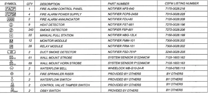
The fire alarm system installed in Engineering IV is a modern design consisting of a Notifier NFS-640 brand mass notification fire alarm control panel (FACP) that networks out to a building wide network of initiating devices and notification appliances as well as various other components. The majority of initiating devices are smoke detectors and manual pull stations. Sprinkler heads are also initiating devices and a water flow switch will send a signal to the FACP. There are also many wall mounted strobe lights and horn strobe appliance throughout the building. As can be seen in Figure 15, the fire alarm system component schedule of Engineering IV shows a system that is typical of a large academic or office building with similar occupancy use.
Figure 15. Engineering IV As-Built Fire Alarm System Schedule
26
Fire Alarm Code. The type of system as indicated on the as-built drawings is an “AUTOMATIC AND MANUAL FIRE ALARM SYSTEM WITH SPRINKLER MONITORING, ELEVATOR CONTROL INTERFACE AND HVAC SHUTDOWN”. This essentially means that the fire alarm can be activated by the automatic detection of the smoke or heat detectors or manually activated using the manual pull stations. The activation of the sprinkler system also notifies the main panel. Upon an alarm, the elevators will shut down, move to the bottom floor or the lowest floor without smoke, and open the doors until the system is reset. The HVAC system includes fire dampers that close upon smoke detection in the air handling system. This feature prevents unnecessary smoke movement to other parts of the building.
Another important aspect of this building's fire alarm system communication sequence is that upon an alarm signal the Fire Alarm Control Panel (FACP) will notify the Cal Poly campus police station through a remote fire alarm panel located at the station. This is known as a protected premises system. A police officer will be dispatched to investigate the situation and decide if the fire department needs to be called. The FACP will send a signal directly to the local fire station if the alarm is a sprinkler system water flow issue. The Cal Poly facilities department states that the estimated Fire Department response time is approx. 3 minutes. Different facilities and organizations will manage this type of communication
differently. Some facilities let building managers be the first investigators, some let third party companies do the work. It is important that whoever takes on this responsibility must be trained to assess whether a fire emergency warrants a call to the fire department or not.
Fire Alarm Control Panel
The Fire Alarm Control Panel (FACP) is the brains of the fire alarm system. Modern FACP systems are powerful computers with software programs that have input and output
capabilities. All fire alarm devices are connected to the FACP. The initiating devices such as smoke alarms, heat detectors, and water flow switches signal to the FACP that a fire emergency is detected. Upon these signals, the FACP then activates
notification appliances such as strobe lights, horns, and voice messages to alert occupants. The FACP can also
communicate to relay switches to shut off air circulation, shut down elevators, and activate smoke barriers among other actions. It also signals or calls remote systems or responders such as the building manager, police station, or fire station. The FACP also signals when there is a problem in the system such as a sprinkler system malfunction or a bad smoke detector. The FACP has a keypad for input
27
alerts. A separate laptop computer can also be connected the FACP to download software updates or adjust how the panel is programmed.
The model used in Engineering IV is the Honeywell Notifier NFS-640 (see Photo 4). The fire alarm devices are connected through wire circuits that are run
from the devices to the FACP through conduit. This particular FACP has the capability to connect up to 64 circuits. The wiring connections for the various system devices are labeled. As can be seen in Appendix C there is an input keyboard for system analysis and program adjustments. There is also a graphic display.
Although designed over 10 years ago, this system is still very sophisticated and includes a high level of capabilities. Also included in the FACP box is a phone and 2-way radio system. A responder such as a building manager or fire department
personnel will likely come and observe the fire alarm panel early in a fire alarm situation. That person will be able to communicate using the box phone or radio to fellow responders. As is typical for multi-story facilities, the main FACP is located in a utility room on
the 1st floor. The FCPS’s (see Photo 5) act as a junction box, device circuit extender, and back-up power sources for the device circuits on the different floors. They are connected directly to the primary building power source but there are also backed up by batteries in the boxes in case of primary power outages.
Another accessory to the FACP are the annunciator displays. These are display panels that are mounted in places that are easier for responders to look at, such as separate floors. There are two of these for each floor of Engineering IV. They provide a condensed format of information that is displayed on the FACP graphic display. However, the annunciator displays could be located in other places that a fire department responder might be able to get to quicker for various reasons.
An important aspect of the fire alarm system is its programmed sequence of operations. The fire alarm control panel has a computer installed with a programmable software
application that controls the sequence in which the fire alarm system will process. Once a fire alarm initiating device such as a smoke detector activates, the fire alarm performs several actions in a sequential order. In the case of the alarm system in Engineering IV, the sequence would be as follows:
1. Annunciate on FACP
2. Annunciate at Remote Annunciator 3. Sound the General Alarm
4. Activate All Roll Down Doors and Fire Shutters 5. Recall Associated Elevators
6. Shutdown Associated Air (HVAC) Unit
Photo 5, Fire Alarm Power Supply Box
28
7. Annunciate at Remote 24 Hours Attended Location The full Sequence of Operation matrix is included in Appendix E.
Initiating Devices:
Initiating Devices are fire alarm components that alert people and the fire alarm control panel if available, that there is an emergency due to a fire. There are two types of typical initiating device. Manual initiating devices are typically manual pull stations that one might see at egresses from rooms or buildings. These pull stations are used by building occupants who theoretically would pull the lever that would sound the space or building fire alarm and if available the main fire control panel. Another type of initiating device actuates automatically such as heat and smoke detectors, or water-flow detectors from a sprinkler system. Once a fire starts, these automatic initiating devices sound and alarm and/or
send an alarm signal to the fire control panel based on a set activation temperature.
There are 22 Notifier Brand NBG-12LX Manual Pull Stations throughout the building (see Photo 6). In accordance with article 760 of the National Electric Code, these pull stations are to be mounted 48” above the finished floor. These pull stations or “alarm boxes” are located throughout Engineering IV in accordance with chapter 17 of NFPA 72:
17.15.9.4 Manual fire alarm boxes shall be located within 5 ft (1.5 m) of each exit doorway on each floor.
17.15.9.5 Additional manual fire alarm boxes shall be provide so that the travel distance to the nearest manualfire alarm box will not exceed 200 ft (61 m), measured horizontally on the same floor.
17.15.9.6 Manual fire alarm boxes shall be mounted on both sides of grouped openings over 40ft (12.2 m) in width, and within 5 ft (1.5 m) of each side of the grouped opening.
29
There are 243 Notifier FSP-851 Smoke Detectors installed throughout the building (see Photo 7). The number of these devices relative to all other fire alarm system components reflects the high dependency on these for notification
of a fire emergency. These are photoelectric type smoke detectors that have a fixed activation
temperature of 135oF (57oC). NFPA 72 specifies that these detectors are to be spaced no more than 30 ft (9.144m) from each other for ceiling heights of 10 feet or more, with smooth ceilings. There are some smooth ceilings in the staff offices, classrooms, some common areas, and other spaces in Engineering IV. There are also many classrooms, laboratories, and combinations of the two that have exposed ceilings. These detectors
in these cases are mounted on structures or side walls that are located in optimum locations. Duct smoke detectors are another important initiating device that are installed in the air handling units (AHU). These AHU’s are apart of the building’s HVAC system, and they normally supply conditioned air throughout. The majority of the supplied air is returned to the AHU through return air systems located through vents that are often located near the supply
registers. If a fire develops somewhere in the building, the smoke could potentially enter one of the return vents, then travel to the AHU. The duct smoke detector would then initiate a fire alarm through the fire alarm panel which would in turn shut down the AHU thus preventing smoke from being pushed back into the building. Engineering IV has two AHU’s mounted on the roof of the building. Both of these AHU’s contain two Notifier FSD-751P duct smoke detectors.
Alarm Notification Appliances:
There are 61 and 69 wall mount strobes and wall mount horn strobes respectively throughout the building. The intent is to provide
visual and/or audible alerts to building managers and occupants during a fire emergency. The strobe lights provide the visual alert and horn strobes provide a visual and audible alert. Both the strobe lights and horns must provide a range of visual and audible alerts to be effective. It is not possible to provide the exact same light and sound levels at every square inch of a facility. The objective is to optimize the ability to alert occupants without harming them or expending resources more than necessary. The requirements of
Photo 7, Smoke Detector
30
how to space and locate these devices are in Chapter 18 of NFPA 72, 2019 Edition. Strobes lights should be spaced and located based on the amount of the device light output (candelas), and the space area. The strobe lights used in this building are System Sensor brand,
S1224MCW, see Photo 8. The strobe lights specification sheets indicate that these devices can put out up to 75 candela or (cd’s) of light. In accordance with table 18.5.5.5.1 (a) of NFPA 72, 2019, a single 75 cd strobe is adequate for a 45 x 45 sq ft. The objective is to make sure
occupants can see the strobe light flashing from any point in the space. The strobes installed in Bldg. 192 seem to generally follow the NFPA requirements give or take a few feet. Most
classrooms and laboratories throughout the building have single strobe lights or horn strobe lights. Most of the rooms are within the space limits of the light output of these strobes, however there are some rooms that may need to be revisited and analyzed to ensure strobe visibility is available throughout the space. The horns can be set to various dBA levels up to 86 dBA in accordance with the vendor data sheets. For a business or educational occupancy, NFPA 72, 2019 Edition, Table A.18.4.4, indicates an ambient sound level to be 54 and 45 dBA
respectively. Tests have shown that noise dBA levels drop 6 dBA every distance doubled. NFPA 72 requires that the horn device provides a minimum dBA level of 15 over the ambient. The horns installed in Building 192 are adequate for this buildings application if adjusted correctly. This installation should be surveyed in the field for accuracy.
Location and Spacing:
The location and spacing of the various fire alarm system components should be based on NFPA 72. The design of Engineering IV was based on
the 1999 edition as noted on the as-built drawings. NFPA only published as far back as the 2007 edition, however. In general, it appears that the locations of the fire alarm devices are adequate, but it is recommended that a survey be done as soon as possible to identify any areas that are significantly different from the current codes. In accordance with NFPA 72, 2019 edition, initiating devices should be located in accordance with Chapter 17 and Annex B. The design, height and slope of ceilings have significant impacts to where smoke and heat detectors can be mounted and located. In the case of Engineering IV, there are a few different types of ceilings. Many of the classrooms and laboratories have
high exposed ceilings that have HVAC ducts, hanging lights, and wiring conduits as well as a sprinkler piping system. In this case, the smoke detectors are mounted on hangers positioned
31
just below all of the equipment in the ceiling (see Photo 9). There are also some classrooms, administrative areas, and various other common areas that have drop down ceiling grids. Paragraph 17.7.3.2.3.1 states the following:
17.7.3.2.3.1* In the absence of specific performance-based design criteria, one of the following requirements shall apply:
(1) The distance between smoke detectors shall not exceed a nominal spacing of 30 ft (9.1m) and there shall be detectors within a distance of one-half the nominal spacing, measure at right angles from all wall or partitions extending upward to within the tip 15 percent of the ceiling height.
(2) All point on the ceiling shall have a detector within a distance equal to or less than 0.7 times the nominal 30 ft (9.1m) spacing (0.7s).
The smoke detectors throughout the building generally follow this location and spacing scheme. Although there are only a few heat detectors in the buildings, these should be mounted in accordance with Table 17.6.3.5.1.
The notification appliances, strobes and horn/strobe combination devices are located in accordance with NFPA 72, Section 18. Strobe lights need to be able to provide the proper light output based on the space dimensions, and the horns must provide the proper alarm volume for all occupied areas.
The System Sensor strobe lights provide various adjustable candela levels based on the power voltage. For 12 or 24 voltage applications, the strobe can be adjusted from 15 to 75 candela. At a 24 volt application, the strobe can be adjusted from 30, 75, or 110 candela. In accordance with Table 18.5.5.5.1(a) of NFPA, 2019 edition, these settings are adequate for a 20 x 20 ft, 45 x 45 ft, and 54 x 54 ft areas respectively.
Wiring:
Having the right wiring connecting the fire alarm devices to the FACP is an important aspect not to be overlooked. It should not be assumed this is a simple action as it involves understanding the voltage used and the amperage capacity of individual devices and system components. Table 3 shows the wire type designation and description that is used in the fire alarm system for this building. This is a typical design drawing format. As can be seen in this
32
case, two sizes of wire are used which are 14 AWG and 16 AWG. Components that need lower current to operate are typically data transmissions such as a Signaling Line Circuit (SLC) cable. Devices such as horns or voice message speakers typically need more current to operate so those wires may be a larger gauge. Current and voltage capacity requirements should be calculated to ensure that circuits are designed within their capacity. An example of this calculation is shown Table 4. Two different circuits of two separate Fire Alarm Power Supply (FCPS) panels are calculated for current and voltage capacity. These two circuits have several components attached and therefore good examples of whether the wire used meets the
requirements. Two different Notification Appliance Circuits (NAC) were assessed as shown. NAC circuit 6 is connected to a panel on the first floor. There are several strobe and horn/strobe combination devices on this circuit, and it can be seen the voltage drop from all those
components is about 3.103 v, which is about a 12.9% drop. NAC circuit 9 which is on the second floor of the building is similar to NAC circuit 6. There are a few less components and this is reflected in the lower voltage drop. Again, these requirements are within the listed component parameters.
Table 4, Voltage Drop Calculations
Secondary Power:
A fire alarm system must work when there is a primary power outage. Building power outages can last for minutes or they can last for days, maybe even weeks. This depends on the various situations such as how bad the damage that caused the outage is and how fast the power company and contractors can fix the situation. Regardless of the power outage situation, the fire alarm system must be able to work at all times while there are occupants in the
building. Otherwise there is a situation where lives can be in danger because the occupants of the building may not know a fire has happened. In a building with multiple floors, this risk of casualties is greater, as their egress paths and times are more difficult and longer the higher the floor.
Because of this situation, back up batteries are typically included in the Fire Alarm Control Panel box and the remote Fire Alarm Power Supply boxes to provide Secondary Power. NFPA 72, 2019 Edition requires that a secondary power source can provide 24 hours of standby power service and 5 minutes of alarm service. FCPS 2 of Engineering IV is analyzed in the Figure
NAC
Circuit (110 cd, 0.209 amp)Strobe Strobe (75 cd, 0..160 amp) Strobe (30 cd, 0.090 amp) Strobe (15 cd, 0.059 amp) Horn/Strob
e (110 cd, 0.167 amp)
Horn/Strobe (75 cd, 0.167
amp)
Wire
Size Resistance (ohms) Length (feet) Total Current (amps)
Voltage Drop Drop %Voltage
6 4 1 1 3 1 2 14 2.525 340 1.807 3.103 12.93
NAC
Circuit Strobe (75 cd, 0.160 amp) (15 cd, 0.059 amp)Strobe (75 cd, 0.167 amp)Horn/Strobe (15 cd, 0.073 amp)Horn/Strobe Wire Size Resistance (ohms) Length (feet) Total Current (amps) Voltage Drop Drop %Voltage
33
7 to provide an example of a required battery capacity given in amp-hours. In this case, the battery capacity needed is over 4.3 amp-hours for this particular FCPS. The specification for the FCPS-24S8 provides a minimum battery capacity of 7.0 amp-hours. However, this unit is
capable of housing up to 18 amp-hour batteries that are available for order through Notifier. It is assumed that the minimum battery life of 7 amp-hours are adequate for all of the panels in Engineering IV since the quantity of devices are similarly distributed in all of the panels. However, it is recommended that a full calculation of the FACP and FCPS panel circuits be assessed and recalculated as soon as possible to ensure that the correct battery capacities are provided.
Figure 16, Battery Capacity Calculation
Description Standby Current Per Unit (AMPS) QTY
Total Standby Current Per Unit (AMPS) Total Aalrm Current Per Unit (AMPS) QTY Total System Alarm Current (AMPS)
FCPS 0.12 x 1 = 0.12 1.6 x 1 = 1.6
Strobes 0 x 16 = 0 0.209 x 16 = 3.344
Horn/Strobes 0 x 18 = 0 0.213 x 18 = 3.834
0.12 8.778 Required Standby Hours Total System Standby Current (AMPS) Required Standby Capacity (Hours)
24 x 0.12 = 2.88
Required Alarm Time (HOURS) Total System Alarm Current (AMPS) Required Alarm Current (AMP-HOURS) 0.0833 x 8.778 = 0.7312
Required Standby Capacity + Reqired Alarm Capacity Added Safety Factor of 1.2
34 Installation and Maintenance Documentation:
NFPA 72 requires initial testing and commissioning of the fire alarm system before the building is turned over to the owner by the general contractor. This should have been included in the System Record of Completion as shown in Chapter 7 of NFPA 72, 2019 edition:
1) Property Information
2) Installation, Service, Testing, and Monitoring Information 3) Documentation of Software
4) Description of Service 5) Power Requirements 6) Circuits
7) Remote Annunciators 8) Initiating Devices 9) Notification Appliances 10)System Control Functions 11)Interconnected Systems
12)Certifications and Approvals (with signatures from the associated authorities) 13)Other supplementary information
Having the record of completion is important to have available for building managers to be able to maintain the system in the future. Facilities personnel can change over frequently, and the System Record of Completion would be the most comprehensive document of the system details. This was not available for this report, but it is recommended that this be either
retrieved, and compared to the current system in case there have been modifications since the initial construction completion. If the initial records cannot be retrieved, then it is
recommended that a fire protection consultant be hired to survey the system to create a new document. This document should include a recommissioning of the system.
Commissioning is an important practice for building management systems. These systems are complex as they often involve a central computer that takes in data then make decisions based on the that data. In the case of fire alarm systems, the commissioning requirements are identified in NFPA 4. Commissioning efforts help to ensure that when initiating devices such as a manual pull station or smoke detector are activated, the signal is reliably sent to the FACP. The FACP must then reliably send signals to the notification devices such as strobe lights, horns, or sprinkler systems for example. This must all be methodically tested up installation of the system to make certain the components work when they are supposed to. For example, a horn may be activated in test mode. All relevant building
35
such an automobile. Imagine during the construction of a car if the engine was installed and then sold without any testing. Would a consumer be confident that everything was going to work the first time the ignition was turned?
Summary:
Engineering IV has an adequate and reliable designed Fire Alarm System. The design meets the requirements of NFPA 72. Even though the original design was based on the 1999 edition, it still appears to meet the 2019 edition in terms of the requirements for location and spacing of alarm devices. It also meets the requirements for the secondary power
requirements. The Fire Alarm Control Panel is still modern and sophisticated enough for today’s requirements. The initiating devices such as smoke detectors are located within NFPA 72
current code. The secondary power system appears to meet requirements.
The aspect that requires more investigation is the condition of the system today. Initial commissioning certifications and maintenance records were not available for this report. These should be assessed by a consultant including field surveys if necessary. Re-commissioning of the system is recommended in the near future. Maintenance logs should be reviewed if available and assessed for necessary updates.
Smoke Management:
A unique feature of this building is the smoke barriers between the second and third floors (see Photo 10). The three floors of the building are connected by the main central stairwell of the building and several openings in the east corridors of the second and third floors. These features help define these connected areas as an atrium in accordance with the
36
International Building Code (IBC), section 201. Section 404 of the IBC states that atriums that connect more than two stories are required to have smoke control system and section 909 states that this can be a mechanical or passive system.
The smoke barriers and enclosure on the third floor, act as a passive smoke control system. The corridor openings have steel barriers that are actuated by motors closing off the openings when signaled by the alarm system. The smoke barrier/enclosure at the top of the middle building stairwell on the third floor becomes fully enclosed when the smoke release doors actuate. The door to the barrier is magnetically released when signaled by the Fire Control Panel upon smoke detection. Sprinklers are located around the exterior and interior perimeters of the smoke enclosure glass for the sole purpose of keeping the glass cool so as not to break at high fire heat rates. There are also smoke curtains that drop down from the ceiling in front of the elevators to protect elevator occupants from being engulfed with smoke as the doors open. These are also actuated upon a signal from the Fire Alarm Control Panel.
Prescriptive Analysis Summary:
Engineering IV was designed and built in accordance with all the appropriate safety and building codes meant to aid occupants in evacuating Engineering IV promptly during a fire event. The proper alarm and notification system is available to let occupants and first
responders know when there is a fire event. There is a water sprinkler system throughout the building designed to try to suppress any fires that might happen. A smoke management system is installed to limit smoke spread throughout the building. The structure of the building is designed to resist failure due to a significant fire for 2 hours to provide adequate time for occupants to evacuate the building. The building is designed with the required amount of exits on each floor and provides them within the required distances from any point.
37
Performance Analysis
Introduction:
The objective of the performance analysis is to assess whether occupants of Building 192 can exit the premises before harmful untenable conditions occur due to a fire event. We’ve concluded thus far that fire protection components of Engineering 4 are compliant with the appropriate building and safety codes through the prescriptive analysis. However, the
performance analysis helps to support whether it is probable that all of those fire protections components and systems of the building will help get occupants out safely.
This analysis will show that in general, occupants can evacuate the facilities in a safe manner before untenable conditions occur. This is based on the estimated design fires developed and results of simulation modeling. Design fires were developed on what is estimated to be the most probable types of fires that could occur in the facility. These design fires are subject to the experience and knowledge of the fire protection engineer. While the design fires provide characteristic information about the fires, it is necessary to model this fire due to the complexity of all the possibilities during a unplanned fire event. The optimum way to model these design fires is through the NIST’s Fire Dynamic Simulation (FDS) application. The FDS application allows complex calculations based on the inputs provided. The outcomes of this model can be visually represented through several applications. The application used for this report is Pyrosim.
Fuel Sources:
A discussion of potential fuel sources is necessary when developing Design Fires. This is because fire modeling requires understanding of the characteristics of a fire in terms of size and growth rate. For academic engineering facilities, the potential fuel sources vary greatly. Some examples of potential common fuels are wood cabinets, various plastics in such forms of furniture and laboratory equipment, flammable liquids and chemicals, stored cardboard, and the list goes on and on. Goals for design fire characteristics is to simulate a combination of highly probably and highly dangerous potential fire scenarios.
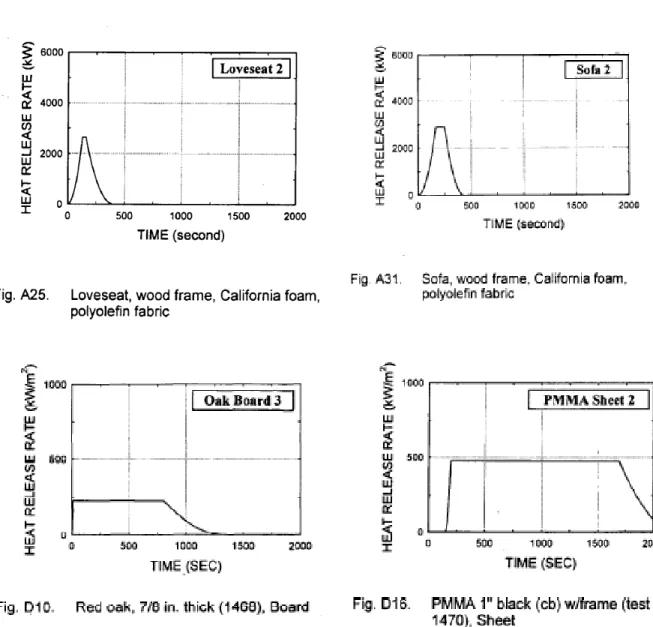
Published data is available for heat characteristics of many materials based on standard laboratory tests. While tests in a laboratory can be much different than an actual fire event, these data points provide a basis for estimation. Kim and Lilley’s Heat Release Rates of Burning Items5, includes several data tables containing fire growth rates of several materials such as
38
wood cabinetry, chairs, desks, and other materials that might be found in Engineering IV. Fire sizes and growth vary from single digit kW fires up to around 6 MW fires with slow to fast growth rates relative to a standard t-squared fire growth.
Table 5 shows a sample of heat release data tables from Kim and Lilley’s data. Heat release vs fire growth rates were recorded for many materials associated with furniture. Materials vary greatly in their maximum heat release rates and growth rates.
39
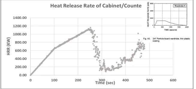
Figure 17 shows several graphs of tested materials of heat release rates vs time. As can be seen, there are several types of materials that were tested, this is only an example of the data in this reference. Other heat release data are available. As can be seen, there is a wide variety in the maximum heat release rates and fire growth rates.
40
RSET vs ASET:
An understanding of the Required Safe Egress Time (RSET) and Available Safe Egress Time (ASET) are necessary to provide a performance assessment of the building. The RSET is an estimated time of how people move and evacuate the building during an emergency fire event. This involves the time from when a notification of fire is given to the time it takes for people to start moving towards the emergency exits, or pre-movement. There have been many studies regarding human behavior in this area. Along with collected empirical data, this information can be used to estimate RSET. ASET is the time it takes for conditions to become untenable for occupants during a fire as characterized in a specific design fire. Untenable conditions include high temperatures, heat fluxes, toxicity from smoke, and visibility diminishment. ASET needs to be greater than RSET to support evacuation of all occupants in a safe manner. To put this in other words, the analyses need to show that people can evacuate the building before the proposed fire causes conditions that can harm or kill occupants.
RSET Analysis:
Introduction:
The method of calculating RSET involves understanding human behavior relative to occupant movement in an emergency situation, and the effects of different aspects of the building such as exit path capacities, stairways, and others. The following paragraphs will discuss the aspects of the building and the methods used to estimate human movement. Although there has been much data through various studies developed, the methods used to estimate human movement cannot determine actual events. This information will help in identifying possibly shortcomings and therefore improve risk mitigation during emergency events.
Impediments to efficient egress:
41
Figure 18. Some dead ends that may cause problems during egress
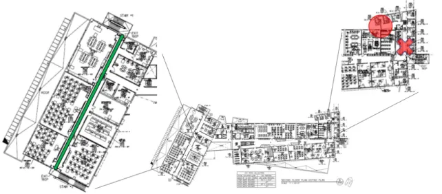
On the second floor of the building as shown in Figure 19, the west end of the building has two very easily accessible exit passageway to the northwest and southwest fire exit stairwells. The east end of the building has similar dead-end issues as the first floor. A significant fire in the office closest to the fire exit could cut off the remaining offices to the north. The remaining classes and laboratories in the middle and west side of the building have adequate alternative evacuation means.
Figure 19. Second floor potential dangerous egress areas
42
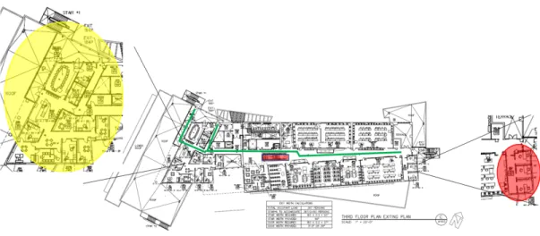
southwest corner of the building has several turns before getting to the northwest stairwell. Exit signs in the area need to be clear to lead occupants in the right direction. Students in the eastern side of the building have a long way to travel to the northwest stairwell if the east end of the building is cut off. Once students get to the west end of the building, they would have to traverse a few turns to get to the exit. The middle stairwell of the building on the third floor is cutoff to go downstairs as it has a smoke containment built on to the stairwell area that will close off automatically in case of a fire.
Figure 20. Third floor has potential egress problems
Occupant Characteristics:
The number of students in the building will vary throughout the week with the peak probably during typical working hours such as 8:00 am to 4:00 pm. Students will occupy the building during night classes also, and there will probably be students working in laboratories during the weekend also. Faculty personnel will probably be in the building either teaching or working in their offices on a regular basis. Other personnel will probably stagger in and out of the building.
Most of the time, students will probably be clustered together in classrooms. However, there will be many times when students will be by themselves or with just a few people working on projects in laboratories. It cannot be assumed that the normal population is fully familiar with the building layout at any given time. There are a wide range of people with various knowledge of the building. There will be many freshman students who are new to the building as well as senior students who have been in the building for several years.
43
difficult enough for older adults to leave buildings during fire alarms, young adult students may find it very difficult to make the right decisions in that scenario.
Total Evacuation Time:
The time it takes to evacuate a building is a key element in assessing the egress effectiveness. The analysis for this report is based on the hydraulic method of egress as
described in Chapter 59, Employing the Hydraulic Model in Assessing Emergency Movement of the SFPE Handbook. Required Safe Egress Time (RSET) is made up of the different phases of evacuation as follows:
RSET6 = td+ tn+ tp-e+ te
td = Time from fire ignition to detection: That is the detection phase
tn= Time from detection to notification of occupants of a fire emergency; that is, the
notification phase
tp-e =Time from notification (or cue reception) until evacuation commences; that is the
pre-evacuation phase
te = Time from the start of purposive evacuation movement until safety is reached; that
is, the evacuation phase.
Both tdand tn are determined by the individual fire scenarios and technical capabilities
of the fire alarm system in place. Fire detection can be activated by persons activating manual pull down stations, a sprinkler head activating, HVAC smoke detector activations, or smoke detectors as well as by other means. In the design fires of this report, the fire detection is activated by smoke detectors. The smoke detectors installed throughout Engineering IV are a photoelectric type. This means that particles of smoke will deflect a light beam in the smoke detector to a sensor which triggers a signal to the fire alarm system. The detection of the smoke for these smoke detectors depend on how fast smoke rises or moves to the detector. To model the time of smoke detector activation in the FDS simulation application, the program allows input parameters for photoelectric smoke detectors. The Notifier FSP-851 brand smoke detectors installed in Engineering IV have a 0.5% to 2.35% per foot obscuration. This metric output is provided in the FDS results for every period of simulated of time listed throughout the model.