Sharif University of Technology
Scientia IranicaTransactions B: Mechanical Engineering www.scientiairanica.com
Comparative study of the eects of two types of ribs on
thermal performance of solar air heaters
A. Boulemtafes-Boukadoum
a,b;, A. Benzaoui
band H. Daaou Nedjari
a,b a. Centre de Developpement des Energies Renouvelables, CDER, Algiers,16340, Algeria.b. LTSE, Faculte de Physique, USTHB, Algiers, 16000, Algeria.
Received 1 December 2015; received in revised form 28 August 2016; accepted 1 October 2016
KEYWORDS Solar energy; Solar air heater; CFD;
Articial roughness; Transverse rib; Heat transfer.
Abstract. This paper aims to analyze uid ow characteristics and heat transfer augmentation in the air duct of a solar air heater using CFD techniques. The air duct has a rectangular section, the top wall is the glazing and the bottom one is the absorber provided with transverse rectangular or squared ribs. The simulations are performed in the turbulent regime and RANS formulation is used to model the ow and resolve mass, momentum, and energy equations using Finite Volumes method. The air ow analysis shows that the velocity prole is not disturbed by the ribs outside the laminar sublayer. Heat transfer analysis based on the calculation of Nusselt Number, friction factor, and thermo-hydraulic performance highlights the heat transfer enhancement and no big friction losses are recorded. A comparative study between two rib shapes (square and rectangular) is performed, which shows better thermohydraulic performance of the rectangular ribs. © 2017 Sharif University of Technology. All rights reserved.
1. Introduction
The main advantages of Solar Air Heaters (SAH) in comparison with solar water collectors are the non-existence of boiling, corrosion, and freezing problems and reduced tightness requirements. Conventional solar air heaters are composed of:
Transparent glazing: made of glass, it allows the solar radiation to pass through;
An absorber: it acts like a black body to absorb the maximum solar radiation.
Besides the conventional SAH, there are some new SAH congurations with an absorber made of porous
*. Corresponding author. Tel.: +213 23 18 90 51; Fax: +213 23 18 90 53
E-mail address: a.boulemtafes@cder dz (A. Boulemtafes-Boukadoum)
doi: 10.24200/sci.2017.4243
media or having storage bed to improve their thermal performance [1,2].
However, currently, solar air heaters have a mar-ket share signicantly less than solar water collectors (0.8% of the nominal installed capacity in the solar heating and cooling market: 151.7 GWth) [3]. The main reason for this is low thermal performance of SAH due to bad heat transfer between the absorber and the owing air.
The most ecient solution is to break the laminar sub-layer formed in the vicinity of the absorber, which is resistant to heat transfer. This could be achieved by using articial roughness.
Heat transfer enhancement techniques in heat exchangers do exist [4,5] and some of them are used in solar air heaters [6]. Unlike heat exchangers, articial roughness in solar air heaters is used on one single wall, namely, the absorber, that receives solar radiation and converts it into heat through a heat transfer medium (air). The other walls are smooth. In addition, the Reynolds number characterizing the air ow through
the solar air collectors is much lower than those of the heat exchangers. Several studies have been carried out on the eect of articial roughness, commonly used in heat exchangers, in the solar air heater, taking into account the specicities of them. Many correlations based on experimental studies have been developed. These correlations involve the heat transfer coecient, the Nusselt number, and the friction factor for each type of ribs. In the literature, numerous review studies are available, which give an overview of rib geometry and shape used in heat exchangers and those adapted to solar air collectors [7-10]. A comparative study of several geometries of the rib employed by various researchers to improve thermal performance of solar air heaters has been reported in order to nd out the optimal rib pattern. From experimental studies, we can cite Karwa [11] who presented the results of an experimental study on heat transfer and friction factor in two rectangular ducts. One was provided with rectangular ribs, the other was smooth. The ducts had an aspect ratio (W/H), which varied between 7.19 and 7.75; the roughness relative height (e/D) varied between 0.0467 and 0.050. The relative pitch (e/P) between the ribs was equal to 10. The experiments were conducted for Reynolds numbers ranging between 2800 and 15000. The results showed an increase in the Stanton number by about 65 to 90%, while the friction factor reached 2.68 to 2.94 times that of a smooth duct. Tanda [12] investigated articial ribs geometry used in the duct of the solar air heater. Angled continuous ribs, transverse continuous and broken ribs, and discrete V-shaped ribs were considered as rib congurations.
More recently, new review analysis and research articles have been published [13-15] as proof of the great interest in and the importance of this heat trans-fer technique. Some authors investigated the eect of three-side articially roughened solar air heaters on the enhancement of Nusselt number and found that it was superior by 21-78% over one-side roughened solar air heater for the range of parameters investigated. How-ever, the friction factor increases in the range of 2-38%. The maximum value of heat transfer enhancement ratio for three-side roughened solar air heater with respect to one-side roughened solar air heater has been found to be 2.654 for the range of parameters investigated [16]. Optimal thermo-hydraulic performance of three-side articially roughened solar air heater of high aspect ratio has been analyzed by Prasad [17], who concludes that the optimal thermo-hydraulic performance con-dition corresponds to the optimal value of roughness Reynolds number. Also, correlations for the average friction factor (fr) and average Nusselt number (Num)
have been developed in terms of the geometrical rough-ness and ow parameters [18].
Studies using CFD techniques were fewer in the last decade [19,20], but their number is in constant
growth because of the computer technology develop-ment and several numerical codes available [21-23]. 1.1. Selection of type and shape of ribs
In our literature survey, it has been shown that repeated ribs are considered as the most eective technique to enhance forced convection heat transfer in SAH [24]. For xed transverse ribs, penalty of friction loss is almost twice the increase in heat transfer. In order to set up thermal performance of the SAH, we have to take into account both heat transfer and friction factors to nd out the best thermo-hydraulic performance.
1.2. Eect of the cross section of the roughness
The cross section of the roughness has an eect on the separation region and, thus, the turbulence level reached by the uid ow. The friction factor for circular section ribs is lower than that for rectangular or square section ones. This is due to the decrease in the size of the separation region [25], which results in reduced inertial losses and increase in friction factor. With the decrease in the separation region, the level of disturbance also decreases, resulting in a lower heat transfer. Another factor responsible for the decrease in the Nusselt number is the drop of the convective exchange surface in circular cross section roughness. Some authors provided their conclusion after performing CFD analysis to study the eect of articial roughness on heat transfer enhancement in solar air heaters. For transverse ribs, growth in the friction factor is almost twice the increase in heat transfer. The best performance was recorded for ribs with rectangular section in the range of the studied parameters [11,19,26].
Another important criterion, which has not been investigated enough, is that the rib height should not aect the ow out of the laminar sublayer [6,19].
As a result, we intended to highlight the eects of two types of ribs (rectangular and square) on heat enhancement in solar air heaters. For this purpose, we planned to examine both the air ow characteristics (by plotting vertical air velocity prole around the rib) and heat transfer enhancement (Nusselt number and friction factor).
Our studied conguration consists in rectangular section channel; the top surface is the glazing and the bottom one is the absorber heated with uniform heat ux that represents the solar radiation received by the absorber (200-600 W/m2). In order to approach
the real operation mode of solar air heaters, we have considered 2 m long channel. The absorber is provided with articial ribs (e/D = 0.05, p/e = 10). A comparative study between the two rib shapes (square or rectangular) is carried out for a number of inlet
parameters (velocity inlet, heat ux, and temperature inlet) with Reynolds number ranging from 3000 to 20000. The eect of inlet parameters on thermo-hydraulic performance of SAH will be investigated and discussed. To verify that the ribs do not perturb the airow, we will analyze the vertical velocity prole around the ribs in dierent sections of the duct. 2. Geometry description
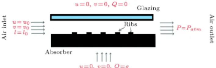
In this work, we intend to numerically investigate the eect of rib shape on air ow and heat transfer enhancement in SAH. For this purpose, we have chosen the following 2D geometry: a rectangular duct provided with articial roughness on its lower wall. The top wall represents the glazing and the bottom one is the absorber provided with transverse (rectangular or squared) ribs heated with uniform ux that represents the solar radiation (Figure 1).
The choice of a two-dimensional geometry is based on the results of a numerical analysis by Chaube [19], who conducted two 2D and 3D analyses and compared the results with the experimental results of Karwa [11]. 3D analysis was performed with 1,203 million cells
Figure 1. Schematic view of the solar air heater duct and the computational domain.
and the 2D one was carried out with 113, 006 cells. The results showed that even for less than 1/10th the number of cells, the 2D analysis gave comparable results. It is because the eect of the secondary ow is negligible for the continuous transverse roughness. Therefore, in our following simulation, we will use 2D geometry, which allows us to save on computing time and PC RAM memory.
2.1. Validation case
The rst part of this work aims to validate our numerical model. For that purpose, we have selected the following geometry that was studied by Chaube et al. [19] and Tanda [24]:
L = 640 mm; H = 20 mm;
e = w = 3 mm (square rib); p = 40 mm:
The air ow is assumed to be turbulent and stationary. The following boundary conditions are applied to the solution domain (Table 1).
2.2. Solar air heater case
To approach the case of solar air collector, we have chosen the following domain solution: a rectangular duct, provided with transverse (square or rectangular) ribs with relative height (e/D = 0.05) and relative pitch (p/e = 10). To approach the SAH operating mode, the heat ux intensity imposed on the absorber surface varies from 200 to 600 W/m2and the inlet temperature
varies from 283 to 303 K. The air ow is assumed to be turbulent and stationary and Reynolds ranges from 3000 to 20000. The boundary conditions applied are presented in (Table 2).
Table 1. Boundary conditions applied for the validation case. Boundary
condition Inlet Outlet Glazing Absorber
u 1.6 to 8 m/s / 0 0
v 0 / 0 0
T 293 K / / /
q / / (Adiabatic) 1.1 kW/m2
p / Patm / /
I 3% / / /
Table 2. Boundary conditions applied for the present study. Boundary
condition Inlet Outlet Glazing Absorber
u 1.5 to 8 m/s / 0 0
v 0 / 0 0
T 283-303 K / / /
Q / / (adiabatic) 200-600 W/m2
p / Patm / /
3. Mathematical formulation
Considering the air ow in the channel with heat transfer, the mathematical model applied is composed of the conservation equations of mass, momentum, and energy in two dimensions with the following assump-tions:
The ow is two-dimensional, turbulent, and station-ary;
The thermophysical properties of the air are sup-posed to be constant;
The thermal conductivity of the walls and ribs is supposed to be constant.
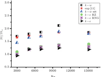
Since the ow is assumed to be turbulent, we use the RANS formulation to predict the air ow [6]. The selection of the best turbulence model is achieved by comparing the predictions of ve dierent two-equation closure models (k-" standard, k-" RNG (Renormalization Group Theory), k-" RZ (Realizable), k-! Standard, and k-" SST) with experimental results available in the literature [6,11]. We solve continuity, momentum, and energy equations for each turbulence model, with Reynolds number varying from 3000 to 20000. The same simulation has been conducted for a smooth duct of the same dimensions as roughened once in order to compare the results and, thus, highlight the heat transfer enhancement due to articial roughness.
Stanton number is one of the most important parameters in heat transfer; therefore, we calculate it for the smooth duct (Sts) and the roughened one. The
ratio (St/Sts) is a good indicator of the enhancement
in heat transfer. As shown in Figure 2, the model k-! SST has been found to yield results closer to the experimental results than the other models do. Based on previous studies [6,19] and according to the literature review [27,28], k-! SST model is adopted to
Figure 2. Comparison between the predictions of ve turbulence models and experimental results.
close turbulence equations. The transport equations for k-! SST are:
@ @t(k) +
@
@xj(kui) =
@ @xj
k@x@k j
+ Gk Yk+ Sk; (1)
@ @t(!) +
@
@t(!ui) = @ @xj
!@x@! j
+ G! Y!+ S!; (2)
where:
Gk The generation of turbulent kinetic
energy due to mean velocity gradient; G! The generation of !;
k The eective diusivity of k; ! The eective diusivity of !;
Yk The dissipation of k due to turbulence;
Y! The dissipation of ! due to turbulence;
Sk and S! User-dened source terms
4. CFD Analysis
CFD analysis based on Finite Volumes method is used for the resolution of continuity, momentum, and energy equations. For discretization of the governing equa-tions, we use second-order upwind scheme. SIMPLE algorithm is applied to treat the coupling between ve-locity and pressure. \Veve-locity inlet" condition has been considered as inlet boundary condition and \Pressure outlet" as outlet boundary condition.
According to the problem geometry, we have generated a two-dimensional multi-blocs non-uniform numerical grid. Since the inter-rib region is very important, we have rened the grid near the walls and have veried that y+ < 5 for all simulations in order to solve the turbulence equations in the viscous sublayer. To check out that the solution is independent, several grids have been tested.
5. Results and discussion 5.1. Validation case
This conguration was studied by Tanda [24] and Chaube et al. [19]. The results obtained by numerical analysis using the k-! SST model have been compared to the results obtained by these two authors.
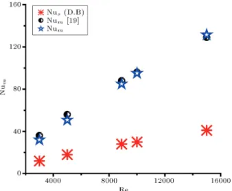
Figure 3 shows the evolution curve of the average Nusselt number versus Reynolds number. We can nd very good agreement with Chaube's curve. In a recent study, Tanda [12] compared experimental results with the results predicted by various correlations of
Figure 3. Nusselt number as a function of Reynolds number.
smooth channel (tubes). It was found that Dittus-Boelter correlation gave the best results. To highlight the enhancement in Nusselt number, we compare our results for the roughened duct with those for a smooth one using Dittus-Boelter correlation given below [14]:
Nus= 0:023Re0:8Pr0:4: (3)
We can notice that the spread of Nusselt numbers for ribbed channel and the smooth one (DB) is quite large. We notice a signicant increase of 1.5 to 4 times in Nusselt number for Reynolds number in the range of 3000 to 20000. This result was foreseeable, because ribs aect the ow by creating separation and reattachment zones that are responsible for increase in turbulence; thus, heat transfer is enhanced.
On the other hand, we calculate the friction factor for dierent Reynolds numbers using the rela-tionship [14]:
fr = P Dh 1=2u2
mL: (4)
The results obtained are shown in Figure 4. We can see that the friction factor decreases as the Reynolds num-ber increases before reaching a relatively constant rate. This is explained by the fact that when Re increases, the thickness of the viscous sublayer decreases, leading to the generation of more vortices that are responsible for energy loss [26]. We also notice that our results are relatively close to those obtained by Chaube et al. [19]. In comparing to the curve in Blasius's equation (smooth duct), it is obvious that the use of articial roughness contributes to increase in friction factor for all Reynolds numbers tested.
5.2. Solar air heater 5.2.1. Air ow analysis
To understand the mechanism of heat transfer between the air and the heated surface of the absorber mainly
Figure 4. Friction factor as a function of Reynolds number.
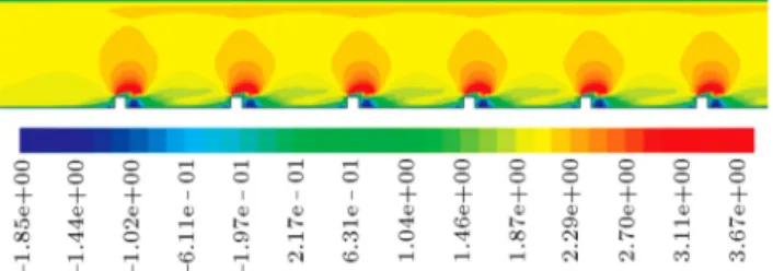
Figure 5. Longitudinal velocity component distribution around rectangular ribs (Re = 4870).
Figure 6. Longitudinal velocity component distribution around rectangular ribs (Re = 7300).
in the inter-roughness region, it is important to analyze the characteristics of the uid ow, which are respon-sible for the mechanism transfer.
Figures 5 and 6 represent the longitudinal velocity component (ux) distribution around rectangular ribs
for two Reynolds number values. We can note that the lower velocity value is recorded in the uid layers adjacent to the walls. Downstream from the rib, velocity is very low, sometimes negative, corresponding to recirculation areas. Due to changes in the ow direction, an over-speed area appears above the rib where the velocity increase reaches 150%. When the Reynolds number increases, we can see that the recirculation zone downstream the rib widens because the reattachment length increases with the Reynolds number [10]. We can notice almost the same phe-nomenon for the square rib (Figures 7 and 8).
Figure 7. Longitudinal velocity component distribution around square ribs (Re = 4870).
Figure 8. Longitudinal velocity component distribution around square ribs (Re = 7300).
Figure 9. Sectional positions of velocity proles.
and in order to verify that the rib does not aect the ow out of the laminar sublayer, we plot the air velocity prole (magnitude) in several transversal sections of the air duct for three Reynolds numbers. A comparison between rectangular and square ribs is also presented. The transversal sections occupy the following abscissae as shown in Figure 9: X1 = 0:15 m, X2 = 0:19 m,
X3= 0:205 m, X4= 0:230 m, and X5= 0:290 m.
At X1 position, the ow is far from the rib and
velocity prole has a parabolic shape for all Reynolds numbers, whatever the cross section (rectangular or square) (Figure 10). As the ow approaches the rib (X2), the velocity prole is distorted on its lower side
(Figure 11) and this distortion is more pronounced for high Re numbers for both square and rectangular ribs. At this location, ow is in the start of separation zone downstream the rib. At X3, the ow is exactly
above the rst rib (Figure 12). It is noted that the lower part of the velocity prole is highly distorted because the ow has reached the over-speed area where velocity values raise from 90 to 160%. The maximum value is recorded for Re = 10960. It should be noted that this raise is more noticeable in the case of square roughness; this can be explained by the fact that rib surface is lower for square ribs, thus the ow more quickly reaches the rib edge and is earlier in the over-speed area. This phenomenon is more apparent in the
Figure 10. Velocity prole in the SAH air duct at X1= 0:15 m.
zoom that we applied to the lower side of the vertical velocity prole (Figure 13). Downstream from the rib, at X4position, the ow reaches the large recirculation
area (Figure 14). ow velocity decreases quickly until it becomes zero. The distortion in the velocity prole is more pronounced when Re increases in the case of square roughness for the same reason cited above. Further, at X5 position, the ow is in the middle
of the recirculation zone and in the vicinity of the attachment point, which is a strong velocity gradient area. The lower part of the prole undergoes a very strong disturbance, where a sudden decrease in speed and, then, a slight increase are observed (Figure 15). 5.2.2. Heat transfer analysis
When the air ow velocity and turbulence intensity are low, energy transfer is mainly done by conduction. When Re increase and mixing between the hot uid and cold uid is important, it contributes signicantly to the heat transfer enhancement [19]. Figure 16 shows the evolution of average Nusselt number with Reynolds number for rectangular and square roughness. We can notice that Nu increases almost linearly with Re.
Figure 11. Velocity prole in the SAH air duct at X2= 0:19 m.
Figure 12. Velocity prole in the SAH air duct at X3= 0:205 m.
Figure 13. Zoom on the lower side of the velocity prole in the SAH air duct at X3= 0:205 m.
The vortex generated by ribs into the boundary layer increases the heat transfer rate, but also causes loss of energy, resulting in the rise in friction factor. Thus, Nusselt number and the friction factor for roughened surfaces are higher than those for smooth surfaces. One
can see that Nusselt number curves for rectangular and square ribs are substantially identical.
Figure 17 shows friction factor evolution for square or rectangular depending on the Reynolds number. As expected and conrmed in the
lit-Figure 14. Velocity prole in the SAH air duct at X4= 0:230 m.
Figure 15. Velocity prole in the SAH air duct at X5= 0:290 m.
Figure 16. Average Nusselt number as function of Re number.
erature [21,22], the friction factor decreases when Reynolds number increases. Indeed, friction factor is high at low Reynolds numbers because the laminar
sub-Figure 17. Friction factor as a function of Re.
layer is thick enough to submerge the rib; moreover, the viscous forces are important enough to absorb distur-bances caused by ribs. We can also observe that friction
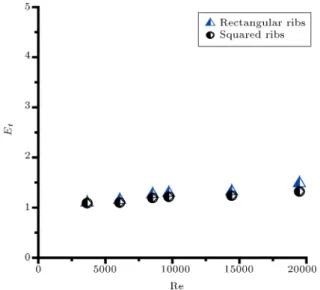
Figure 18. Eect of Reynolds number on global thermohydraulic performance parameter.
factor values remain moderate in the range of Reynolds numbers with a slight superiority for square roughness. In Figure 18, we plot the global thermohydraulic performance parameter curve presented by many au-thors [19,20,26]:
Et= (Nu=Nul)
(fr=frl)1=3
: (5)
A good performance parameter (Et> 1) is recorded in
the range of Reynolds numbers used. Furthermore, Et
raises signicantly as Reynolds number increases. We can notice that the rectangular roughness shows better performance, according to Chaube [19] results.
Figure 17 shows evolution of the friction factor for square or rectangular depending on the Reynolds number. As expected and conrmed in the literature [15,19], the friction factor decreases when Reynolds number increases. Indeed, the friction factor is high at low Reynolds numbers because the laminar sub-layer is thick enough to submerge the rib; moreover, the viscous forces are important enough to absorb disturbances caused by ribs. We can also observe that the values of friction factor remain moderate in the range of Reynolds numbers with a slight superiority for the square rib.
In Figure 18, we plot the curve for the global thermohydraulic performance parameter (Et). A good
performance parameter (Et > 1) is recorded in the
range of Reynolds numbers used. Furthermore, Et
raises signicantly as Reynolds number increases. We can notice that the rectangular rib shows better per-formance, in good agreement with Chaube [19] results. In solar thermal systems, the solar radiation intensity received by the absorber surface changes during a day and seasons. For this reason, we have found it useful to analyze the performance of the solar
Figure 19. Eect of heat intensity on global
thermohydraulic performance parameter (Re = 14430).
Figure 20. Eect of inlet temperature on global thermohydraulic performance parameter (Re = 14430).
sensor in air according to the quantity of heat Q received by the absorber. Hence, we plot the curve of global thermohydraulic performance parameter (Et)
as a function of the heat Q received by the absorber in Figure 19. We nd out that it has a small eect on the thermal hydraulic performance of both rectangular and square ribs.
The thermal hydraulic performance parameter is in direct relation with Nusselt number and the friction factor; we want to study its variation with the function of inlet temperature; thus, we plot the following curve (Figure 20). This parameter appears to be dependent on To. However, his variation remains to be very low
for both rectangular and square ribs. 6. Conclusion
analysis on air ow and heat transfer in SAH's duct provided with transverse (rectangular and square ribs):
We found out that the use of articial roughness had a signicant inuence on improving the heat transfer between the air and the absorber, since we recorded a signicant raise compared to a smooth absorber. For square roughness, we recorded an improvement in Nusselt number by nearly 4 times for Re = 15000;
We proved that the use of articial transverse ribs gave rise to a good thermal hydraulic performance with a slight superiority for rectangular roughness;
The air ow analysis showed that the velocity prole was not disturbed by the articial roughness outside the laminar sublayer and, thus, no big friction losses were recorded;
The results of our numerical simulation showed good agreement with experimental and numerical results available in the literature.
Nomenclature Air density
cp Specic heat of the air
Dh Hydraulic diameter
e Rib height fr Friction factor
h Convective heat transfer H Duct height
I Turbulence intensity L Duct length
p Pitch (distance between 2 successive ribs)
Q Heat ux density applied to the absorber surface
T Air temperature u Air velocity um Mean ow velocity
w Rib width
P The pressure drop between the inlet and the outlet of the duct
Air thermal conductivity References
1. Saxena, A. and El-Sebaii, A.A. \A thermodynamic review of solar air heaters", Renewable and Sustainable Energy Reviews, 43, pp. 863-890 (2015).
2. Bouadila S., Lazaar, M., Skouri, S., Kooli, S. and Farhat, A. \Energy and exergy analysis of a new solar air heater with latent storage energy", International Journal of Hydrogen Energy, 39, pp. 15266-15274 (2014).
3. Kramer, K. \Interaction of regulation and innovation: Solar air heating collectors SHC 2012", Energy Proce-dia, 30, pp. 1311-1321 (2012).
4. Nouri-Borujerdi, A. and Seyyed-Hashemi, M.H. \Nu-merical analysis of thermally developing turbulent ow in partially lled porous pipes", Scientia Iranica B, 22(3), pp. 835-843 (2015).
5. Mohammadi Pirouz, M., Farhadi, M., Sedighi, K., Ne-mati, H. and Fattahi E. \Lattice Boltzmann simulation of conjugate heat transfer in a rectangular channel with wall-mounted obstacles", Scientia Iranica B, 18(2), pp. 213-221 (2011).
6. Boulemtafes-Boukadoum, A. and Benzaoui, A. \CFD based analysis of heat transfer enhancement in solar air heater provided with transverse rectangular ribs", Energy Procedia, 50, pp. 761-772 (2014).
7. Akpinar, E.K. and Kocyigit, F. \Energy and exergy analysis of a new at-plate solar air heater having dierent obstacles on absorber plates", Applied Energy, 87, pp. 3438-3450 (2010).
8. Yeh, H.M. \Upward-type at-plate solar air heaters attached with ns and operated by an internal re-cycling for improved performance", Journal of the Taiwan Institute of Chemical Engineers, 43, pp. 235-240 (2012).
9. Chamolia, S., Thakura, N.S. and Sainib, J.S. \A review of turbulence promoters used in solar thermal systems", Renewable and Sustainable Energy Reviews, 16, pp. 3154-3175 (2012).
10. Singh Hans, V., Saini, R.P. and Saini, J.S. \Perfor-mance of articially roughened solar air collectors-A review", Renewable and Sustainable Energy Reviews, 13, pp. 1854-1869 (2009).
11. Karwa, R.K. \Experimental studies of augmented heat transfer and friction in asymmetrically heated rectan-gular ducts with ribs on heated wall in transverse, inclined, v-continuous and v-discrete pattern", Int Commun Heat Mass Transfer, 30, pp. 241-250 (2003)
12. Tanda, G. \Performance of solar air heater ducts with dierent types of ribs on the absorber plate", Energy, 36, pp. 6651-6660 (2011).
13. Singh, S., Chander, S. and Saini, J.S. \Thermo-hydraulic performance due to relative roughness pitch in V-down rib with gap in solar air heater duct{ Comparison with similar rib roughness geometries", Renewable and Sustainable Energy Reviews, 43, pp. 1159-1166 (March 2015).
14. Sharma, S.K. and Kalamkar, V.R. \Thermo-hydraulic performance analysis of solar air heaters having arti-cial roughness-A review", Renewable and Sustainable Energy Reviews, 41, pp. 413-435 (January 2015).
15. Lanjewar, A.M., Bhagoria, J.L. and Agrawal, M.K. \Review of development of articial roughness in solar air heater and performance evaluation of dierent orientations for double arc rib roughness", Renewable and Sustainable Energy Reviews, 43, pp. 1214-1223 (March 2015).
16. Behura, Arun, K., Prasad, B.N. and Prasad, L. \Heat transfer, friction factor and thermal performance of three sides articially roughened solar air heaters", Solar Energy, 130, pp. 46-59 (2016).
17. Prasad, B.N., Kumar, A. and Singh, K.D.P. \Opti-mization of thermo hydraulic performance in three sides articially roughened solar air heaters", Solar Energy, 111, pp. 313-319 (2015).
18. Prasad, B.N., Behura, Arun, K. and Prasad, L. \Fluid ow and heat transfer analysis for heat transfer enhancement in three sided articially roughened solar air heater", Solar Energy, 105, pp. 27-35 (2014).
19. Chaube, A., Sahoo, P.K. and Solanki, S.C. \Analysis of heat transfer augmentation and ow characteristics of a solar air heater", Renewable Energy, 31, pp. 317-331 (2006).
20. Kumar, S. and Saini, R.P. \CFD based performance analysis of a solar air heater duct provided with articial rib", Renewable Energy, 34, pp. 1285-1291 (2009).
21. Yadav, A.S. and Bhagoria, J.L. \Heat transfer and uid ow analysis of solar air heater: A review of CFD approach", Renewable and Sustainable Energy Reviews, 23, pp. 60-79 (2013).
22. Yadav, A.S. and Bhagoria, J.L. \A numerical inves-tigation of square sectioned transverse rib roughened solar air heater", International Journal of Thermal Sciences, 79, pp. 111-131 (2014).
23. Gawande, V.B., Dhoble, A.S., Zodpe, D.B. and Chamoli, S. \A review of CFD methodology used in literature for predicting thermo-hydraulic performance of a roughened solar air heater", Renewable and Sus-tainable Energy Reviews, 54, pp. 550-605 (2016).
24. Tanda, G. \Heat transfer in rectangular channels with transverse and V-shaped broken ribs", Int. J. Heat Mass Transfer, 47 pp. 229-243 (2004).
25. Liou, T.-M., Hwang, J.-J. and Chen, S.-H. \Simulation and measurement of enhanced turbulent heat transfer in a channel with periodic ribs on one principal wall", Int. J. Heat Mass Transfer., 36, pp. 507-517 (1993).
26. Wang, L. and Sunden, B. \Performance comparison of some tube inserts", International Communication in Heat and Mass Transfer, 29(1), pp. 45-56 (2002).
27. Sun, W., Ji, J., and He, W. \Inuence of channel depth on the performance of solar air heaters", Energy, 35, pp. 4201-4207 (2010).
28. Sharif, M.A.R and Liu, W. \Numerical study of turbulent natural convection in side heated square cavity various angles of inclination", Numerical Heat Transfer, Part A, 43, pp. 693-716 (2003).
Biographies
Amel Boulemtafes Boukadoum is a researcher in Solar Thermal and Geothermal Energy Department at Renewable Energy Development Centre (CDER) of Algiers. She obtained the Magister degree in Physics with distinction from the University of Sciences and Technologies (USTHB)/Faculty of Physics in 2010. Currently, she is a PhD candidate in Energetic Physics and Fluid Mechanics at USTHB. Her current research elds include solar energy conversion, solar collectors, heat transfer enhancement, thermodynamics, exergy, numerical modeling, and CFD.
Ahmed Benzaoui obtained the Doctorate in Physics/Fluid Mechanics in France. He joined the Uni-versity of Sciences and Technology (USTHB)/Faculty of Physics in 1982 and, since then, has been very active in both teaching and research. He has taught several courses at both graduate and postgraduate lev-els, namely, heat and mass transfer, thermodynamics, modeling, uid mechanics, etc. His research elds of interest include renewable energy conversion, cooling production techniques, thermal energy conversion, wa-ter treatment, air pollution, etc.
Hada Daaou Nedjari is currently a researcher in the Wind Energy Laboratory at Renewable En-ergy Development Centre (CDER) of Algiers. She received her Master degree in Mechanic and Fluid Dynamics from University of Sciences and Technology (USTHB)/Faculty of Physics, Algiers, in 2010. She is a PhD candidate in Physics. Her research interests include wind energy development and implementation in Algeria, computational uid dynamics and thermal stratication.