Sharif University of Technology
Scientia IranicaTransactions B: Mechanical Engineering www.scientiairanica.com
Aspects of canard-wing vortices interaction in subsonic
ow
A.R. Davari
a;, M. HadiDoolabi
b, M.R. Soltani
cand M. Izadkhah
ca. Department of Mechanical and Aerospace Engineering, Science and Research Branch, Islamic Azad University, Poonak, Tehran, I.R. Iran.
b. Department of Aerospace Engineering, Malek Ashtar University, Tehran, Iran. c. Department of Aerospace Engineering, Sharif University of Technology, Tehran.
Received 11 October 2012; received in revised form 10 October 2014; accepted 15 November 2014
KEYWORDS Canard; Vortex; Interaction; Burst; Delta wing; Tip vortex.
Abstract. A series of subsonic wind tunnel tests were conducted on a canard-wing conguration to study the interaction of canard and wing vortices. Both the canard and the wing in the present experiments had equal sweep angles. The velocity contours were measured using a total-static rake at three chordwise positions at front, middle and rear parts of the wing in a plane perpendicular to the wing surface. The experiments were performed at various combinations of attack and canard deection angle. The results show a close relationship between the strength of the vortices and the outcome of their interaction. According to the present ndings, when the wing strong vortex is exposed to the strong vortex of the canard, the result of this interaction would be a weaker vortex on the wing with a smaller size than the original two vortices, while a weak vortex on the canard interacted with a strong vortex on the wing, amplies it and results in a stronger vortex on the wing surface. This has also been shown to be true when a strong canard vortex interacts with a weak vortex on the wing. The result would again be a stronger vortex on the wing surface.
© 2015 Sharif University of Technology. All rights reserved.
1. Introduction
At high angles of attack, delta wings produce high lift due to the vortical ow system over their suction sides, which enable maneuvering capability at low speeds. In addition, high sweep delta wings are desirable in high speed cruise regimes. Close-coupled delta wing and canard congurations have great advantages on the wing oweld. Canard has favorable eect on the aerodynamic characteristics of aircraft such as instantaneous pitching control, increasing maximum
*. Corresponding author. Tel.: +98 21 44868536
E-mail addresses: ardavari@srbiau.ac.ir (A.R. Davari); hadidoolabi@yahoo.com (M. HadiDoolabi);
msoltani@sharif.edu (M.R. Soltani); m izadkhah@yahoo.com (M. Izadkhah)
lift and a potential to increase lift to drag ratio and maneuverability [1].
In the late 1950's, widespread cutting-edge re-searches were conducted with the subject of vortical ow over delta wings. Er-El [2] carried out an extensive study on the downstream eects of the canard sweep angles and positions of the loading of a delta wing. His results showed that highly swept canard produces stronger leading edge vortices that induce lower pres-sure region over the wing; a result which is less evident in the moderate sweep canards.
Calarese [3] performed an experimental study to investigate the interaction of the vortices shed by canard and wing leading edges, and their eects on a close-coupled canard-wing conguration in dierent wind tunnels. He investigated the eects of the model size, the Mach number, the angle of attack and the
spanwise blowing eects on the vortex interaction. According to his results, a coplanar canard produces a small favorable interaction between the leading edge vortices, while an o-set canard produced a consider-able increase in the lift to drag ratio.
Rom et al. [4] conducted a series of experimental measurements on the aerodynamic characteristics of several close-coupled wing-canard congurations up to moderately high angles of attack. They compared the longitudinal aerodynamic coecients, the rolled-up vortex trajectories, and the pressure distributions for ve wing-canard congurations. They examined vari-ous canard deections and canard positions relative to the wing. Their results indicate that a positive canard deection causes a slight increase in the maximum lift of the conguration while having only small eect on the variation of the lift as a function of the attack angle. They also reported a decrease in the lift to drag ratio at positive canard deections for small to moderate angles of attack.
Hummel and Oelker [5,6] performed comprehen-sive surface pressure measurements and ow visualiza-tions on various lateral and longitudinal canard posi-tions with dierent setting angles. In their studies, the eects of the body on the oweld were eliminated by using a thin vertical body. From their ndings, canard induces a non-uniform angle of attack distribution on the wing, which suppresses ow separation in the front parts and supports vortex shedding in the rear parts. Due to downwash eects, vortex breakdown is delayed within the wing vortex system. They also found that tendency of merging the two vortices is enhanced by increasing the angle of attack which is more evident for the mid canard congurations.
Up to 1990, the experiments were mostly concen-trated on canard and wing without taking the fuselage eects into account. In 1993, Howard [7] tested a model including canard, wing and fuselage. A tertiary vortex was observed at the juncture of canard and fuselage that had an impact on the resulting ow and was not observed in the earlier researches of wing-canard combinations in the absence of body.
Bergmann and Hummel [8] examined body-wing-canard congurations in a symmetrical ow. Their results show that the eects of canard vortex on the ow over the wing are considerable for large deections and lower canard positions, i.e. the canard surface is located much lower than the wing. However, at very low canard positions, this favorable interference eect vanishes. The vortex breakdown on the canard deteriorates the vortical ow at all angles of attack, and this leads to a considerable loss of lift.
In addition to the experimental studies, various numerical simulations have also been performed on the canard-wing congurations. Eugene [9] solved a thin-layer approximation of the Navier-Stokes equations to
investigate the eects of canard vertical position on a close-coupled, canard-wing-body conguration. The computational results showed favorable canard-wing interactions for the high and mid canard positions. It was revealed that unfavorable results for the low canard conguration are directly attributed to the interaction between the canard and the wing vortices.
Ekaterinaris [10] analyzed the oweld of a canard-wing-body conguration at subsonic speeds and at high angle of attack by a Navier-Stokes ow solver with overset grids. He predicted vortex breakdown as well as its delay due to the canard inuence.
Tuncer and Platzer [11] investigated the subsonic oweld over a close-coupled delta canard-wing-body conguration at high angles of attack using a Navier-Stokes solver. They presented their results in terms of particle traces, surface streamlines and leeward-side surface pressure distributions for both canard-on and canard-o congurations. They found that the presence of canard delays wing vortex breakdown to positions aft of the wing trailing edge.
In recent years, the studies on the aerodynamics of canard-wing body congurations, has mainly been concentrated on the vortical ow control over the lifting surfaces. Canard ow controlled by spanwise pulsed blowing has been found to play an important role in in-creasing the aerodynamic performance of canard-wing body congurations, especially in the circumstances when an indirect wing ow control is desired [12,13].
Cui et al. [14,15] successfully examined forebody slot blowing to postpone the vortex break down onset on a delta wing. They also found that a symmetric blowing on both the upper and the lower surfaces leads to the best performance. To develop a concept to be used as an active ow control actuator for a delta wing, Chung et al. [16] studied the interaction and merging processes of the co-rotating and counter rotating vortex pairs generated in a strake-delta wing conguration, as well as their impact on aerodynamic forces through CFD simulations. They observed that a counter-rotating vortex pair at high angles of attack has a pronounced eect on the overall vortex system and consequently on aerodynamic forces of the delta wing.
Nearly all studies undertaken so far, were concen-trated on the canard eects on the forces and moments of the aircraft or the canard signature on the ow eld over the wing. Though valuable information has already been obtained on the eects of canard on the oweld over the wing, to the authors' knowledge, none was reported to deal with the physical interpretation of the canard-wing vortices interaction and their merge.
In the present research, eects of canard on the wing oweld were investigated for a canard-wing-body conguration. The results include the velocity eld at three chordwise planes normal to the wing
surface. For various combinations of angle of attack and canard deection angle, the eects of canard vortex were studied on the wing oweld. This study revealed the interaction law of canard-wing vortices. The results can be thought of as a dierent view point to the vortex interaction phenomenon. The conditions under which the wing vortex is amplied or attenuated by the canard ow are examined and addressed in the paper. These ndings can be extensively used in nearly all canard-wing ying vehicles at moderate to high angles of attack.
2. Experimental setup and procedure
The experiments were carried out in a subsonic closed circuit wind tunnel with test section dimensions of 0.8 m0.8 m. The maximum attainable speed at the test section is 100 m/sec. Using hot wire anemometry the turbulence intensity at the test section was mea-sured to be less than about 0.1%.
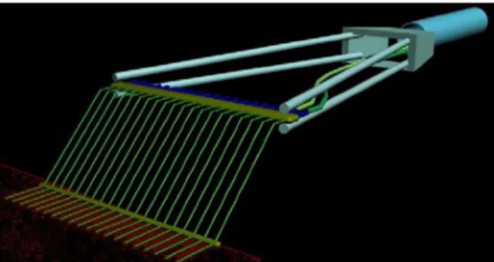
The model considered in the present experiments was a close coupled wing-canard conguration attached on a half body. Figure 1 shows the model installed in the test section along with the rake probes used for the velocity measurements. Both the wing and the canard had a at platform with sharp leading edges.
The wing and the canard were attached on the fuselage in such a way that the wing apex was very close to the canard trailing edge. Table 1 summarizes the geometric characteristics of both planforms.
The velocity eld in a plane perpendicular to the wing surface at three chordwise locations (x=c = 0:44 at the front part, x=c = 0:69 at the middle and x=c = 1:00 at the rear of the wing) at dierent combinations
Figure 1. The model installed in the test section with the rake probes behind.
Table 1. Geometric parameters of the model planforms. Wing Canard Leading edge sweep angle 60 60
Span to chord ratio 0.56 0.62 Thickness to root chord ratio 0.02 0.03 Leading edge bevel angle 15 15
Figure 2. Schematic of the rake designed for the present experiments.
of model angle of attack and canard deection angle was measured. The corresponding canard-o tests on the wing alone conguration were also carried out as well.
The experiments were conducted at a single Reynolds number of 0:825106based on the wing root
chord. The angles of attack were varied from 0to 25
with an increment of 5. The canard deection angles
were measured with respect to the body and ranged from -10 to 10.
The rake used for the measurements was espe-cially designed to impart as minimum disturbance in the eld as possible and was more slender than the conventional rakes. Figure 2 shows a schematic view of the rake manufactured and used in the present experiments. The rake had 10 total pressure and 10 static pressure tubes, which were 10 mm apart. The internal diameter of the tubes was 0.9 mm. Two 45 bends were provided in the tubes to reduce the
interference eects of the supporting system at the position under measurement. The model maximum blockage ratio including wing and canard planform areas was measured to be less than %5.
Due to some restrictions during the test, the rake could not be traversed spanwise in the test section to cover the entire wing span. To retrieve the information regarding the oweld lost by these restrictions, a numerical simulation was also performed over the conguration.
The probes were connected by short plastic tubes to high frequency pressure sensors with 30 kHz acqui-sition rate and 5 psi measuring range located outside the test section. Dierent tube lengths and materials were examined to nd the best choice to reduce the associated losses and time lags.
A high frequency data acquisition system was employed to acquire the data. The acquisition rate was 100 samples per second and the data presented in this paper is an average of 3000 samples for each channel of the A/D board. Total errors encountered by the measured data including the accuracy of the electronic devices such as transducers and acquisition
Figure 3. Typical data uncertainty.
board were estimated to be less than 3%. Figure 3 shows a typical data uncertainty analysis on the total pressure measurements.
3. The numerical survey
As stated earlier, since the rake provided for the present experiments was not wide enough to scan the entire wing span, nor was possible a spanwise traversing of the rake on the wing, only the outboard region of the wing was captured by the rake. To achieve a better insight through the oweld over the entire model, a numerical analysis was carried out on this conguration.
The equation used for the numerical simulations in the present work was the full Navier-Stokes equation for viscous ow which has been discritized on unstruc-tured grids and solved by a commercial code. Since the ow regime was incompressible, the pressure based algorithm was used to solve the equations. To take the simultaneous advantages of k! near the wall and k " for fareld, the k-!-SST turbulence model was used. This model also seems to be a suitable choice to take the ow transition eects into account.
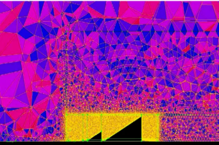
The ow inlet and outlet were considered on a sphere having a radius of 20 times the body length and only half of the model was analyzed owing to symmetry of the problem. The boundary layer mesh was used for near body regions and for the rest of the eld, tetragonal and pentagonal cells were generated. The cell distributions on a longitudinal cross section are shown in Figure 4.
To check the grid independency, 1.0, 1.5 and 2 million cells, i.e. coarse, medium and ne grids, were considered and the same results with a good accuracy were achieved for the two later cases. On this basis 1.5 million cells were chosen for the rest of the analysis. Figure 5 shows the associated results for the model considered in the present experiments.
The Hummel's canard-wing model [17] was rst
Figure 4. The cell distribution at a longitudinal section of the eld.
Figure 5. Grid resolution study on the present model.
considered by the authors to check the numerical settings. The lift and drag coecients have been compared with the Hummel's experimental data. Fig-ure 6(a) and (b) compare the present numerical pre-diction results with the experimental data [18] and as can be seen, good agreement is achieved. The model considered in the present experiments is some-how similar to that of Hummel's [17], regardless of some geometric details, the free stream conditions and canard deection angles. Thus nearly the same numerical settings were used to simulate the model constructed for the present experiments.
4. Floweld description over the model
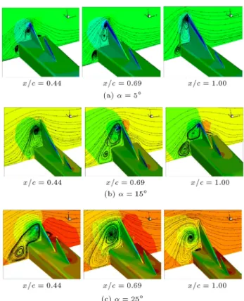
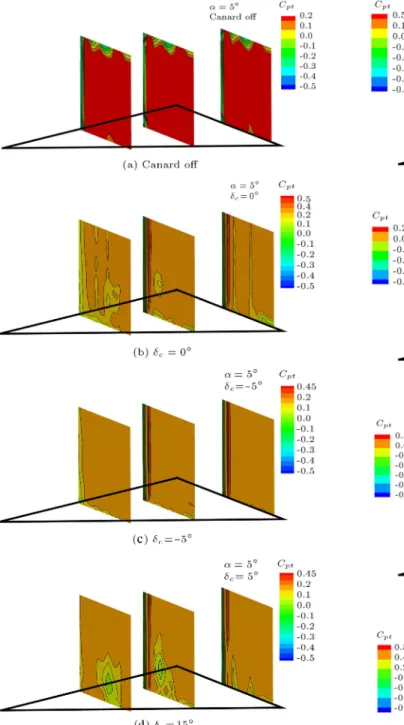
Figure 7 shows the oweld obtained by the numerical simulations over the wing in the presence of canard at three chordwise sections for several angles of attack with zero canard deection.
For = 5 and 15 degrees at x=c = 0:69, the canard vortex is clearly observed which seems to be merged with the wing vortex at x=c = 1 at the trailing
Figure 6. Comparison of the present numerical results for a standard canard-wing conguration with the experimental results of Ref. [17].
edge. For = 25 degrees, neither of the three lateral sections on the wing show the individual canard vortex on the wing. It seems that the two vortices have been completely merged and formed a single vortex at the trailing edge.
Similar ndings were also documented by Hum-mel and Oelker [5,6,17]. According to their experi-mental analysis on a nearly similar canard-wing-body conguration using conical ve-hole probe along with balance data and surface pressure measurements, the canard induced up wash along the leading wing edge increases the eective angle of attack in that region. This increase in angle of attack, in turn, supports ow separation at the leading edge. This mechanism is responsible for the growth of the wing vortex along the leading edge [18]. Hummel's results also show that the canard vortex system under the wing inuence moves above the wing towards the body and, at the same time, downward towards the wing surface. This trajectory is shown schematically in Figure 8.
Figure 7. Sectional oweld on the wing determined by numerical simulations.
Figure 8. Schematic overview of the vortices on a canard-wing conguration at low angles of attack in the absence of viscous eects [17].
5. Results
The numerical simulation result has been compared with the present experimental data for a typical case in Figure 9. As pointed out earlier, the rake used for these experiments, was not wide enough to cover the entire wing span, thus, the experimental data in this gure were according to the rake width rather than the wing span which was the case for the numerical results. Figure 9 shows a good agreement between the numerical and experimental data. However some discrepancies are observed in this gure which are mostly around the vortex core regions on the wing. These are believed to be due to viscous eects and turbulence modeling used in the numerical simulation and the errors associated with the sensor reading and
Figure 9. Typical comparison of the present
experimental results and the numerical simulations on the model under study.
Figure 10. Spanwise velocity distribution; = 5, z=b = 0:143 and x=c = 0:44.
the experimental apparatus. The later has been shown in Figure 3.
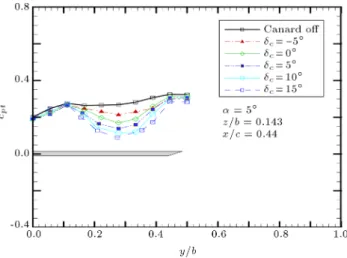
Figure 10 shows the spanwise variations of the total pressure coecient for a distance, z=b = 0:143, above the wing surface and at a chordwise position of x=c = 0:44 at the front half of the wing. For the isolated wing at 5 degrees angle of attack, potential ow dominates and there is no signicant variation in the spanwise velocity. However, for the canard-on cases, the spanwise total pressure has been signicantly reduced.
For zero deection angle of canard, even though the oweld on both the canard and the wing are the same owing to their equal sweep angles, a vortex has been developed over the wing. For a canard deection of -5 for which the eective canard angle is zero, this
vortex becomes weaker. When the canard deection angle increases to 15, the angle seen by the canard
would be 20 and a strong vortex is appeared on the
wing.
Figure 11. Spanwise velocity distribution; = 15, z=b = 0:143 and x=c = 0:44.
Note that at = 5, no vortex is developed over
the isolated wing. Thus the vortex observed over the wing in Figure 10 in the presence of canard is due to the induced eects of canard ow on the wing, which has accelerated the weak ow of the wing to form a relatively strong vortex. Furthermore, from this gure, it can be seen that as the canard angle is increased from -5 to 15 degrees, the width of the low pressure region on the wing also increases, since the canard vortical ow at positive incidence angles aects a wider region on the wing than the negative ones.
Figure 11 shows the spanwise total pressure dis-tribution over the wing for an angle of attack of 15
at a vertical distance, z=b = 0:143, from the wing surface. At this angle, the isolated wing vortex has just matured. According to this gure, the wing vortex for zero canard deection is weaker than that for -5 and -10 degrees deection. This means that as the canard vortex strength decreases, the strength of the vortex induced on the wing increases. The reduction in total pressure over the model, as seen from Figure 11, may be due to the downwash eect of the canard vortex on the oweld over the wing at the location under consideration [18]. For the angles well below that corresponding to vortex burst, the canard downwash reduces the eective angle seen by the wing and as a result, the wing vortex strength reduces. For a weaker canard vortex, this downwash eect reduces and evidently the wing vortex strength increases. One may conclude that at a certain canard deection angle, the combination of the canard and the wing vortices results in a considerable potential ow over the wing, i.e. the viscous eects of the vortex will be diminished.
An interesting phenomenon observed from this gure is that for the chordwise location under consid-eration, i.e. x=c = 0:44, which is at the front half of the wing at = 15, the vortex on the isolated wing
is believed to be due to the canard downwash eect in the front region of the wing, discussed earlier. For the canard-on cases, it can be inferred that at the front regions of the wing, interaction of a strong wing vortex and a strong canard vortex attenuates the resulting vortex on the wing, while a weak canard vortex induces a favorable eect on a strong wing vortex and improves the wing aerodynamic performance.
The authors' previous ndings in an individual study [18,19] revealed that the dominant frequency mode of the canard vortex is higher than that of the wing with the same sweep angle placed downstream. This is due to the canard wake and vortex eects on the wing leading edge vortex, which seems to restrict its activity and decrease its strength. However, at suciently high angles of attack, where both the canard and the wing vortices suciently grow up, the wing vortex strength cannot be as amplied as that of an isolated wing, due to the retarding eects of the canard vortex.
For 25 degrees angle of attack case, shown in Figure 12, the strong wing vortex, once interacted with a weaker vortex of the canard, is amplied and also moved laterally towards the root; the position which is closer to the canard vortex path on the wing, as illustrated schematically in Figure 8.
In this case, where the canard vortex is weaker than the wing vortex due to dierent angles of attack seen by either of them, the canard does not play a retarding role on the wing as was the case for the strong canard vortex. In such circumstances, the wing vortex with its lower dominant frequency takes the advantages of the canard higher frequency spectrum to be amplied. As a result, a strong wing vortex downstream of the weak canard vortex would be stronger than that of the wing in the absence of canard, i.e. the isolated wing. From Figure 11, it is also observed that the minimum total pressure on the
Figure 12. Spanwise velocity distribution; = 25, z=b = 0:214 and x=c = 0:44.
wing not only reduces, but also moves closer to the junction of the wing and the body. As a consequence of combination of the canard and the wing vortices, the resulting vortex is wider and covers a larger portion of the wing surface, which is observed in Figure 12.
Figure 13 shows the spanwise velocity distribution at a middle section on the wing, x=c = 0:69, at 5 degrees angle of attack. It can be seen that the nearly-potential ow over the isolated wing at = 5
has been replaced by a vortical ow in the canard-on ccanard-onguraticanard-on and as the canard deecticanard-on angle increases, the vortex strength induced on the wing also increases. As observed earlier, the best aerodynamic performance has been achieved on the wing when the wing weak vortex was interacted with the canard strong vortex, i.e. the wing angle of attack of 5 degrees and the canard eective angle of 20 degrees.
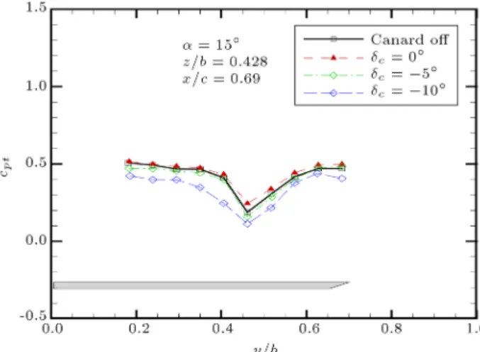
Shown in Figure 14 is the spanwise velocity for section x=c = 0:69 at an angle of attack of 15. The
interaction of the strong wing vortex and the strong canard vortex at zero and -5 degrees canard deection
Figure 13. Spanwise velocity distribution; = 5, z=b = 0:428 and x=c = 0:69.
Figure 14. Spanwise velocity distribution; = 15, z=b = 0:428 and x=c = 0:69.
has reduced the wing vortex strength in presence of the canard. However, for a weaker vortex developed on the canard for -10 deection, its interaction with
the strong wing vortex could successfully increase the resulting vortex strength on the wing.
In this case, the canard vortex is strong enough to dictate its higher frequency modes to the strong wing vortex with a little lower frequency band [19]. Consequently, the canard shows its destructive eect again and the wing vortex is attenuated in comparison to that of the isolated wing.
In Figure 15, the strong wing vortex at = 25
has been amplied by the weaker canard vortex at an eective deection angle of 15. Once again, the result
is a strong vortex, which has been displaced laterally towards the wing root. Further, the vortex on the isolated wing covers less area on the wing than that downstream of the -10 deected canard.
For the trailing edge section at x=c = 1:0 shown in Figure 16, the behavior is similar to that observed in Figure 13 for the middle section. According to
Figure 15. Spanwise velocity distribution; = 25, z=b = 0:428 and x=c = 0:69.
Figure 16. Spanwise velocity distribution; = 5 z=b = 0:428 and x=c = 1:00.
Figure 16, the interaction of the wing weak vortex and the canard strong vortical ow at a canard incidence of 15, corresponding to an eective canard angle of 20,
resulted in a strong vortex on the wing at 5 degrees angle of attack in the presence of canard.
At an angle of attack of 15, where the wing
vortex is matured, Figure 17 shows that the weaker the canard vortex, the stronger would be the wing vortex in the presence of canard. As the canard vortex strength increases, the strength and size of the vortex on the wing decreases. This result has previously been observed at the front and middle sections of the wing.
At 25 degrees angle of attack, where the isolated wing vortex is strong enough, its combination with the weaker vortex of the canard has amplied the wing vortex.
The width of the resulting vortex has also been increased over the wing surface. This situation has been shown in Figure 18.
To have a qualitative view of the ow over the
Figure 17. Spanwise velocity distribution; = 15, z=b = 0:428 and x=c = 1:00.
Figure 18. Spanwise velocity distribution; = 25, z=b = 0:428 and x=c = 1:00.
Figure 19. Velocity eld on the wing at various canard deections; = 5.
wing in the presence of canard, Figures 19, 20 and 21 show the total pressure contours over the wing for canard-o and canard-on cases at various canard deection angles for three angles of attack of 0, 5 and 15 degrees, respectively. The measurements were on the three aforementioned chordwise sections, x=c = 0:44 nearly at the front part, x=c = 0:69 at the mid part, and 1.00 at the rear part of the wing.
Figure 19 shows the velocity eld on the wing at an angle of attack of 5. On the isolated wing
at this angle of attack, as observed earlier, potential ow dominates throughout the surface as shown in
Figure 20. Velocity eld on the wing at various canard deections; = 15.
Figure 19(a). For the canard-on conguration at = 0, the actual angle seen by the canard is 5. Even though
no vortical ow at this angle exists on the canard nor on the isolated wing, according to Figure 19(b), a vortex can be observed at the front part of the wing as a result of merging the potential ows of both canard and wing. For = 5, the eective canard angle is
to that of an isolated wing. When the canard is set to 15 degrees deection corresponding to 20 eective
angle, a relatively strong vortex is developed on the wing at the front and the middle regions, Figure 19(d). Note that the isolated wing itself has no vortex on its surface at this angle of attack. Thus the vortex seen on the wing in the presence of the canard is the result of amplifying the wing ow by the canard oweld.
For an angle of attack of 15, the vortical ow
is developed on the isolated wing as shown in Fig-ure 20(a). For zero degrees canard deection corre-sponding to an eective angle of attack of 15, the
canard vortex aects the wing vortex of the same strength. The result is a weaker vortex on the wing, Figure 20(b). In Figure 20(c) at = 5, the canard
sees 10deection angle and a weaker vortex from the
canard aects the wing vortex. The adverse eect of canard vortex on the wing is decreased here comparing to Figure 20(b) because the canard vortex strength is reduced. For weaker canard vortex at = 10, shown
in Figure 20(d), the wing performance becomes even better than the two former cases with stronger canard vortices.
When the angle of attack is increased to 25
in Figure 21, a strong vortex is dominated on the isolated wing as shown in Figure 21(a). However, though not tested here, this strong vortex could be weakened by the strong canard vortex for zero or positive canard deections. For = 10 in
Fig-Figure 21. Velocity eld on the wing at various canard deections; = 25.
ure 21(b), the actual angle seen by the canard is 15
and the canard vortex would be weaker than that of the wing. The result, as observed, is a stronger vortex especially at the rear parts where the isolated wing vortex is about to bust. However, the weaker vortex of canard could successfully revive this vortex at the trailing edge and increase the wing aerodynamic performance.
6. Concluding remarks
Extensive subsonic wind tunnel tests have been per-formed on a canard-wing-body conguration to study the canard and wing vortices interaction at various combinations of angle of attack and canard deec-tion angle. The total pressure distribudeec-tion at three chordwise sections on the wing in a plane normal to the surface at the section under consideration was measured using a rake. The results, which can be thought as the velocity distribution, show that the wing downstream of canard has a dierent oweld than an isolated one. The canard and the wing vortices are shown to have a strong interaction. The canard vortex can either amplify or attenuate the wing vortex, depending on their strengths. According to the results, when the strong vortex of the wing is exposed to the strong vortical ow of the canard, the outcome would be a weaker vortex. As the canard vortex strength decreases, the resulting vortex increases. On the other hand, in the cases where there is a weak or no vortical ow on the wing, the canard vortex can eectively amplify it and a strong vortex is developed on the wing. These results can be generalized to suggest that the merging of two vortices or the induced eect of one vortex on the other, is a function of the vortices strengths. Once the vortices have dierent strengths, the induced eect or the merging of these vortices results in a stronger vortex, while on the other hand, the merging of two equal strength vortices or the induced eects of either of them on the other may result in a weaker vortex with a smaller size than the two original vortices.
Nomenclature
Body angle of attack, measured with respect to the oncoming ow
c Canard deection angle, measured
with respect to the body p Local static pressure pt Local total pressure
cpt Total pressure coecient
c Wing chord at the root b Wing semi span
x=c Nondimensional chordwise position, measured from the wing apex y=b Nondimensional spanwise position,
measured from the wing root z=b Nondimensional vertical position,
measured from the wing surface.
References
1. Skow, A.M. \An analysis of the Su-27 ight demon-stration at the 1989 Paris air show", SAE paper, No. 901001 (April 1990).
2. Er-El, J. \Eect of wing/canard interference on the loading of a delta wing", Journal of Aircraft, 25(1), pp. 18-24 (1987).
3. Calarese, W. \Vortex interaction eects on the lift/drag ratio of close-coupled canard congurations", AIAA Paper, pp. 87-1344 (1987).
4. Rom, J., Melamed, B. and Almosnino, D. \Exper-imental and nonlinear vortex lattice method results for various wing-canard congurations", Journal of Aircraft, 30(2), pp. 207-212, (March-April 1993).
5. Hummel, D. and Oelker, H.C. \Eects of canard position on the aerodynamic characteristics of a close-coupled canard conguration at low speed", AGARD-Cp-465 (1989).
6. Hummel, D. and Oelker, H.C. \Low-speed character-istics for the wing-canard conguration of the inter-national vortex ow experiment", Journal of Aircraft, 31(4), pp. 868-878 (1994).
7. Howard, R.M. and O'Leary, J.F. \Flow eld study of a close-coupled canard conguration", Journal of Aircraft, 31(4), pp. 908-914 (July-Aug. 1994).
8. Bergmann. A. and Hummel, D. \Aerodynamic eects of canard position on a wing body conguration in symmetrical ow", AIAA Aerospace Science Meeting and Exhibit, 39th Reno, Nevada (Jan. 2001).
9. Eugene, L. Tu \Vortex wing interactions of a close-coupled canard conguration", Journal of Aircraft, 31(2), pp. 314-324 (March-April 1994).
10. Ekaterinaris, J.A. \Analysis of owelds over missile congurations at subsonic speeds", Journal of Space-craft and Rockets, 32(3), pp. 385-391 (May-June 1995).
11. Tuncer, I.H. and Platzer, M.F. \A Computational study of a close-coupled delta canard-wing-body con-guration", AIAA Paper 96-2440-CP (1996).
12. Liu, P., Wen, R. and Zhang, G. \Eects of canard sweep and canard-spanwise blowing magnitude on lift increment", Journal of Aircraft, 43(5), pp. 1369-1371 (September-October 2006).
13. Liu, P., Wen, R., Zhang, G. and Wu, S. \Experimental study of canard-spanwise pulsed blowing on a canard
conguration", Journal of Aircraft, 45(5), pp. 1816-1820 (September-October 2008).
14. Cui, Y.D., Lim, T.T. and Tsai, H.M. \Control of vortex breakdown over a delta wing using forebody slot blowing", AIAA Journal, 45(1), pp. 110-117 (2007).
15. Cui, Y.D., Lim, T.T. and Tsai, H.M. \Forebody slot blowing on vortex breakdown and load over a delta wing", AIAA Journal, 46(3), pp. 744-751 (March 2008).
16. Chung, H.S., Seaver, C.A. and McLaughlin, T.E. \Vortex ow control over a delta wing by co-rotating and counter rotating vortex generator", AIAA Paper 2010-4952 (June-July 2010).
17. Oelker, H.C. and Hummel, D. \Investigations on the vorticity sheets of a close-coupled delta-canard conguration", Journal of Aircraft, 26(7), pp. 657-666 (July 1989).
18. Soltani, M.R., Askari, F., Davari, A.R. and Nayebzade, A. \Eects of canard position on the wing surface pressure", International Journal of Science and Tech-nology, Scientia Iranica, Transactions B: Mechan-ical Engineering, 17(2), pp. 102-107 (March-April 2010).
19. Samimi, S., Davari, A.R. and Soltani, M.R. \Canard-wing interactions in subsonic ow", International Journal of Science and Technology, Transactions of Mechanical Engineering, 37(M2), pp. 133-147 (2013).
Biographies
Ali Reza Davari received his PhD degree in Aerospace Engineering from Sharif University of Tech-nology, Tehran, Iran, in 2006, and is currently fac-ulty member in the Department of Mechanical and Aerospace Engineering at the Science and Research Branch, Azad University, Iran. His research interests encompass experimental and applied aerodynamics, including new prediction and optimization methods and tools in aerodynamics, such as neural networks, DOE/RSM and evolutionary algorithms.
Mostafa HadiDoolabi has been graduated in 2006 with a PhD degree in Aerospace Engineering from Amirkabir University of Technology, Tehran. He is currently a faculty member in the Department of Aerospace Engineering at Malek Ashatr University. His main areas of study are numerical aerodynamics and ight mechanics. He is specially interested in the numerical schemes development for unsteady and high speed ows. Wind tunnel design, calibration and tests have been his recent research areas.
de-gree in Aerodynamics from the University of Illinois at Urbana-Champaign, USA, in 1991, and is cur-rently Professor in the Aerospace Engineering De-partment at Sharif University of Technology, Tehran, Iran. His research interests include unsteady and applied aerodynamics, design and building of wind tunnels and wind turbines, design, building and im-plementation of wind tunnel instruments, and mea-surement methods. He has published over 27
jour-nals and 50 conference papers in his areas of re-search.
Mohammad Izadkhah received his MSc degree in aerospace engineering from Sharif University of Tech-nology. Wind tunnel test has been his primary research interest and he has good experiences in low speed wind tunnel tests, especially wing-body interaction problems in subsonic ow.